Page 834 of 1865
7A INSPECTION
86U07A-058
63U07A-074
63U07A-075
Reverse Idle Gear
1. Worn or damaged bushing.
2. Worn or damaged teeth.
3. Worn or damaged release lever coupling groove.
4. Clearance between sleeve and reverse lever.
Standard: 0.095—0.318 mm (0.004—0.013 in)
Maximum: 0.5 mm (0.020 in)
Clutch Housing, Transaxle Case, Rear Cover,
and Differential Gear Case
Cracks or damage.
Caution
If the clutch housing, transaxle case, or
differential gear case is replaced, adjust the
bearing preload of the shaft gears and the
preload of the differential side bearings.
Bearing
1. Roughness or noise while turning
2. Worn or damaged outer race or rollers
Caution
a) Replace the bearing, the outer race, and the
inner race as a unit.
b)lf the bearing is replaced, adjust the
preload.
Speedometer Driven Gear Assembly
1. Worn or damaged teeth.
2. Worn or damaged O-ring.
Ring Gear Speedometer Drive Gear
Worn or damaged teeth.
Oil Seal
Damaged or worn lip.
63U07A-076
7A—28
Page 835 of 1865
ASSEMBLY 7 A
ASSEMBLY
Note
a) Wash all parts.
b) Apply oil to all friction surfaces.
c) Use new roll pins and retaining rings.
STEP 1 (DIFFERENTIAL)
86U07A-059
Assembly
1. Install the speedometer drive gear and the new
bearing inner race with the SST.
Note
Press to 19,620 N (2,000 kg, 4,400 lb).
2. Install the new bearing inner race with the SST.
Note
Press to 19,620 N (2,000 kg, 4,400 lb).
86U07A-061
7A-29
Page 841 of 1865
ASSEMBLY 7A
8. Measure the clearance between the 1st gear and
differential drive gear.
Clearance: 0.05—0.28 mm (0.0020—0.0110 in)
Maximum: 0.33 mm (0.0199 in)
86U07A-081
9. Measure the clearance between the 2nd gear and
secondary 3rd gear.
Clearance:
0.175—0.455 mm (0.0069—0.0179 in)
Maximum: 0.505 mm (0.0199 in)
86U07A-082
7A-35
Page 843 of 1865
ASSEMBLY 7 A
Bearing Preload
Adjust the bearing preload through the use of adjust shim(s).
83U07A-099
49 G030 381
Outer race
Differential
Outer races
Secondary shaft
assembly
49 G030 382A
Transaxle case
Outer rases
Primary shaft assembly
Outer rase
49 F401 382A
Clutch housing
83U07A-033
7A-37
Page 844 of 1865

7 A ASSEMBLY
Outer race
Selector
76G07A-032
i "k
49 G030 381
49 G030 382A
49 G030 382A
76G07A-033
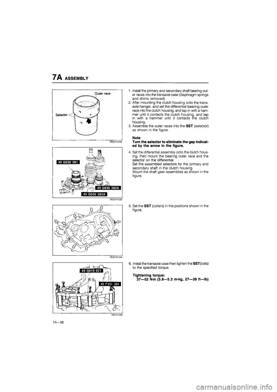
1. Install the primary and secondary shaft bearing out-
er races into the transaxle case (diaphragm springs
and shims removed).
2. After mounting the clutch housing onto the trans-
axle hanger, and set the differential bearing outer
race into the clutch housing, and tap in with a ham-
mer until it contacts the clutch housing, and tap
in with a hammer until it contacts the clutch
housing.
3. Assemble the outer races into the SST (selector)
as shown in the figure.
Note
Turn the selector to eliminate the gap indicat-
ed by the arrow in the figure.
4. Set the differential assembly onto the clutch hous-
ing, then mount the bearing outer race and the
selector on the differential.
Set the assembled selectors for the primary and
secondary shaft in the clutch housing.
Mount the shaft gear assemblies as shown in the
figure.
5. Set the SST (collars) in the positions shown in the
figure.
76G07A-034
6. Install the transaxle case then tighten the SST(bolts)
to the specified torque.
Tightening torque:
37—52
N
m (3.8—5.3 m-kg, 27—38 ft—lb)
76G7A-035
7A-38
Page 846 of 1865

7A ASSEMBLY
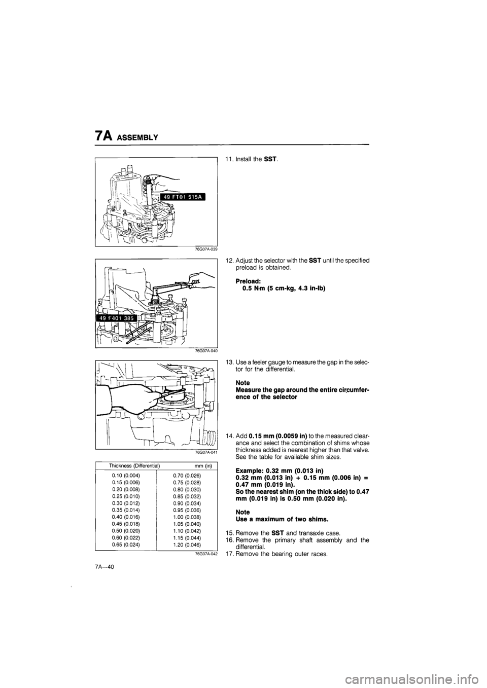
11. Install the SST.
76G07A-039
76G07A-040
76G07A-041
Thickness (Differential)
mm
(in)
0.10 (0.004) 0.70 (0.026)
0.15 (0.006) 0.75 (0.028)
0.20 (0.008) 0.80 (0.030)
0.25 (0.010) 0.85 (0.032)
0.30 (0.012) 0.90 (0.034)
0.35 (0.014) 0.95 (0.036)
0.40 (0.016) 1.00 (0.038)
0.45 (0.018) 1.05 (0.040)
0.50 (0.020) 1.10 (0.042)
0.60 (0.022) 1.15 (0.044)
0.65 (0.024) 1.20 (0.046)
12. Adjust the selector with the SST until the specified
preload is obtained.
Preload:
0.5 N-m (5 cm-kg, 4.3 in-lb)
13. Use a feeler gauge to measure the gap in the selec-
tor for the differential.
Note
Measure the gap around the entire circumfer-
ence of the selector
76G07A-042
14. Add 0.15 mm (0.0059 in) to the measured clear-
ance and select the combination of shims whose
thickness added is nearest higher than that valve.
See the table for available shim sizes.
Example: 0.32 mm (0.013 in)
0.32 mm (0.013 in) + 0.15 mm (0.006 in) =
0.47 mm (0.019 in).
So the nearest shim (on the thick side) to 0.47
mm (0.019 in) is 0.50 mm (0.020 in).
Note
Use a maximum of two shims.
15. Remove the SST and transaxle case.
16. Remove the primary shaft assembly and the
differential.
17. Remove the bearing outer races.
7A—40
Page 847 of 1865
ASSEMBLY 7A
86U07A-102
86U07A-103
76G07A-043
Assembly
1. Install the neutral switch.
2. Install the drain plug.
3. Install the back-up lamp switch.
4. Install the new oil seals with the SST.
5. Install the differential adjust shim(s) and the bear-
ing outer race with a suitable pipe.
6. Install the adjust shims, diaphragm springs, fun-
nel, and bearing outer races.
Note
Install the diaphragm spring as shown in the
figure.
7. Install the bearing outer races with a suitable pipe.
86U07A-105
7A—41
Page 849 of 1865

ASSEMBLY 7A
76G07A-044
76G07A-045
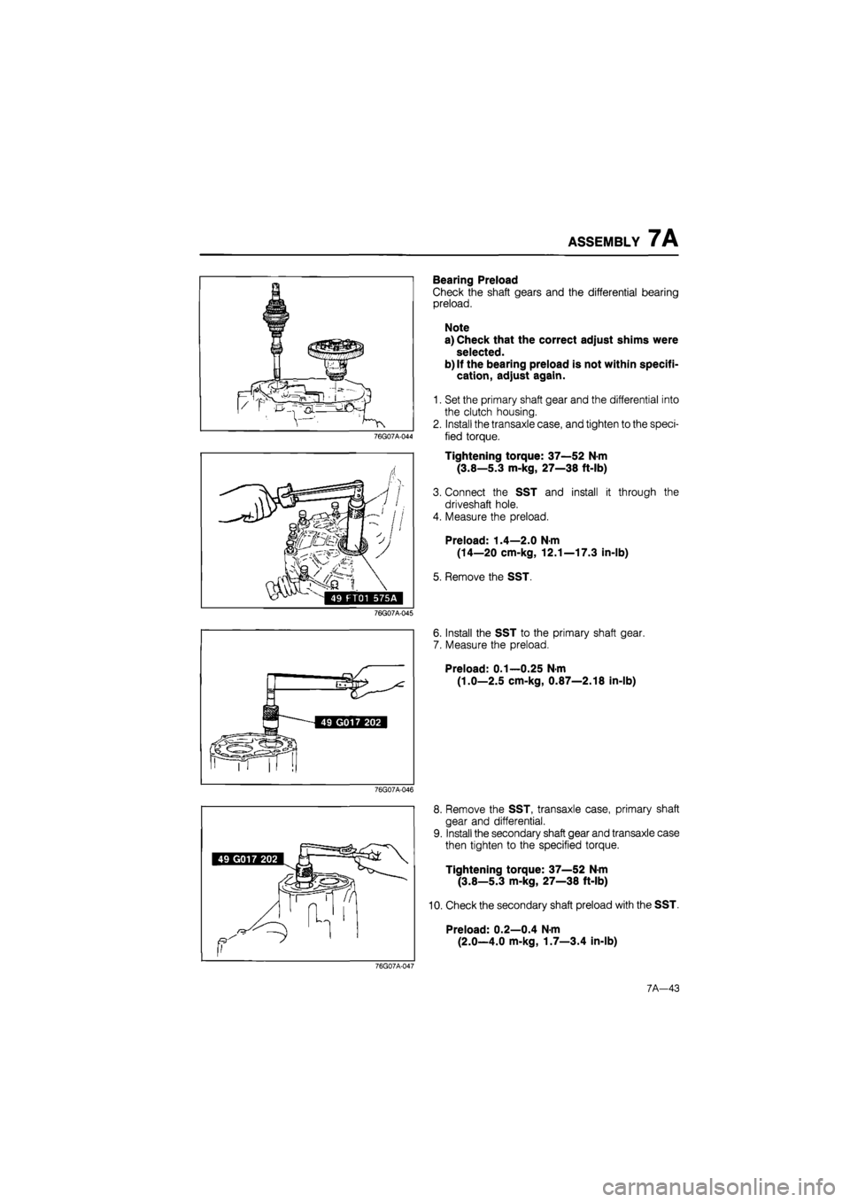
Bearing Preload
Check the shaft gears and the differential bearing
preload.
Note
a) Check that the correct adjust shims were
selected.
b) If the bearing preload is not within specifi-
cation, adjust again.
1. Set the primary shaft gear and the differential into
the clutch housing.
2. Install the transaxle case, and tighten to the speci-
fied torque.
Tightening torque: 37—52 N-m
(3.8—5.3 m-kg, 27—38 ft-lb)
3. Connect the SST and install it through the
driveshaft hole.
4. Measure the preload.
Preload: 1.4—2.0 N-m
(14—20 cm-kg, 12.1—17.3 in-lb)
5. Remove the SST.
6. Install the SST to the primary shaft gear.
7. Measure the preload.
Preload: 0.1—0.25 N-m
(1.0—2.5 cm-kg, 0.87—2.18 in-lb)
76G07A-046
8. Remove the SST, transaxle case, primary shaft
gear and differential.
9. Install the secondary shaft gear and transaxle case
then tighten to the specified torque.
Tightening torque: 37—52 N-m
(3.8—5.3 m-kg, 27—38 ft-lb)
10. Check the secondary shaft preload with the SST.
Preload: 0.2—0.4 N-m
(2.0—4.0 m-kg, 1.7—3.4 in-lb)
76G07A-047
7A-43