1987 MAZDA 626 differential
[x] Cancel search: differentialPage 1280 of 1865
![MAZDA 626 1987 Workshop Manual
DRIVESHAFT 9
[MTX]
DISASSEMBLY
Disassemble in the sequence shown in the figure referring to the disassembly note for specially marked
parts.
Note
a) Clamp the shaft in a vice. Use protectors in MAZDA 626 1987 Workshop Manual
DRIVESHAFT 9
[MTX]
DISASSEMBLY
Disassemble in the sequence shown in the figure referring to the disassembly note for specially marked
parts.
Note
a) Clamp the shaft in a vice. Use protectors in](/manual-img/28/57059/w960_57059-1279.png)
DRIVESHAFT 9
[MTX]
DISASSEMBLY
Disassemble in the sequence shown in the figure referring to the disassembly note for specially marked
parts.
Note
a) Clamp the shaft in a vice. Use protectors in the vice to avoid damage.
b)Do not allow dirt or foreign matter in the joint during disassembly or assembly.
c) Do not disassemble the ball-joint at the wheel side. Do not wipe the grease off if there
is no problem.
d)Do not remove the clip used to secure the outer ring to the ball-joint at the differential
side if there is no problem.
If the clip is removed, replace it with a new one.
1. Boot band
2. Clip
3. Outer ring
4. Snap ring
86U09X-059
5. Ball joint
6. Boot band
7. Boot
8. Clip
9. Sensor rotor (Refer to Section 11)
Clip
1. Make matching marks on the driveshaft and out-
er ring for proper reassembly.
Note
Mark with paint, do not use a punch.
2. Remove the clip.
86U09X-091
9-31
Page 1282 of 1865
DRIVESHAFT 9
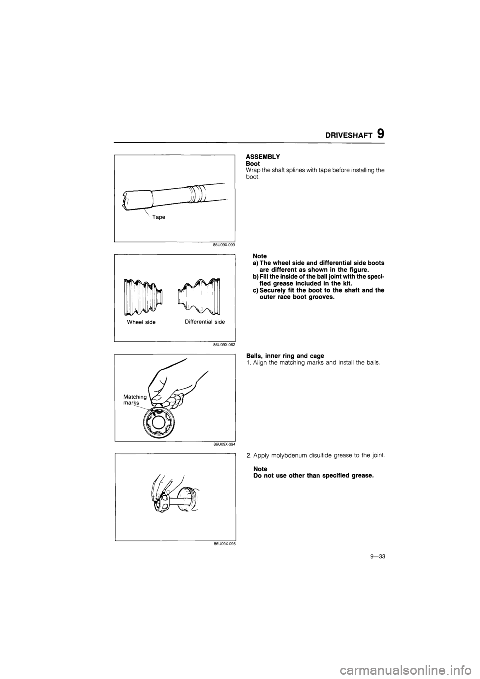
ASSEMBLY
Boot
Wrap the shaft splines with tape before installing the
boot.
86U09X-093
Wheel side
Note
a) The wheel side arid differential side boots
are different as shown in the figure.
b) Fill the inside of the ball joint with the speci-
fied grease included in the kit.
c) Securely fit the boot to the shaft and the
outer race boot grooves.
86U09X-062
Balls, inner ring and cage
1. Align the matching marks and install the balls.
86U09X-094
2. Apply molybdenum disulfide grease to the joint.
Note
Do not use other than specified grease.
86U09X-095
9-33
Page 1285 of 1865
9 DRIVESHAFT
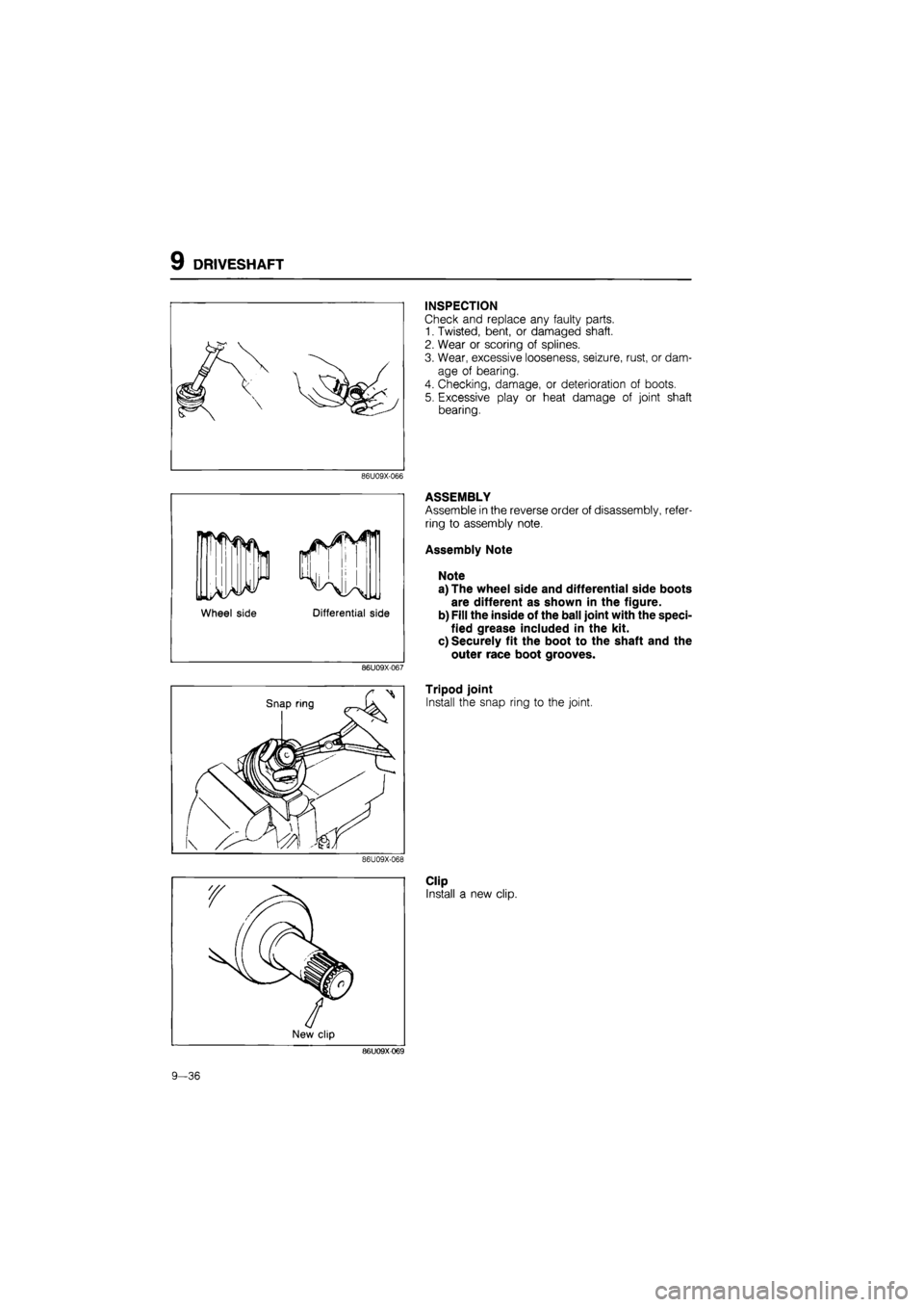
INSPECTION
Check and replace any faulty parts.
1. Twisted, bent, or damaged shaft.
2. Wear or scoring of splines.
3. Wear, excessive looseness, seizure, rust, or dam-
age of bearing.
4. Checking, damage, or deterioration of boots.
5. Excessive play or heat damage of joint shaft
bearing.
86U09X-066
Wheel side Differential side
86U09X-067
ASSEMBLY
Assemble in the reverse order of disassembly, refer-
ring to assembly note.
Assembly Note
Note
a) The wheel side and differential side boots
are different as shown in the figure.
b) Fill the inside of the ball joint with the speci-
fied grease included in the kit.
c) Securely fit the boot to the shaft and the
outer race boot grooves.
Tripod joint
Install the snap ring to the joint.
86U09X-068
Clip
Install a new clip.
86U09X-069
9-36
Page 1828 of 1865
30 TECHNICAL DATA
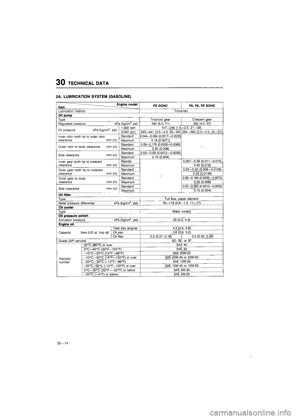
2A. LUBRICATION SYSTEM (GASOLINE)
Engine model Item ____ FE DOHC F6, F8, FE SOHC
Lubrication method Force-fed
Oil pump
Type Trochoid gear Crescent gear
Regulated pressure kPa (kg/cm2
psi)
490 (5.0,
71)
392 (4.0, 57)
Oil pressure kPa (kg/cm2,
psi)
1,000 rpm 147-245 (1.5-2.5, 21-36) Oil pressure kPa (kg/cm2,
psi)
3,000
rpm
343—441 (3.5-4.5, 50-64) 294—392 (3.0—4.0, 43-57)
Inner rotor tooth
tip to
outer rotor
clearance
mm
(in)
Standard 0.044-0.084 (0.0017-0.0033)
—
Inner rotor tooth
tip to
outer rotor
clearance
mm
(in) Maximum 0.18 (0.0071)
—
Outer rotor
to
body clearance
mm
(in) Standard 0.09-0.176 (0.0035-0.0069)
—
Outer rotor
to
body clearance
mm
(in) Maximum 0.20 (0.008)
—
Side clearance
mm
(in) Standard 0.03-0.09 (0.0012-0.0035)
—
Side clearance
mm
(in) Maximum 0.10 (0.004)
—
Inner gear tooth tip
to
crescent clearance
mm
(in)
Standar
—
0.267-0.38 (0.011-0.015) Inner gear tooth tip
to
crescent clearance
mm
(in) Maximum
—
0.40 (0.016)
Outer gear tooth tip
to
crescent clearance
mm
(in)
Standard
—
0.20-0.32 (0.008-0.0126) Outer gear tooth tip
to
crescent clearance
mm
(in) Maximum
—
0.35 (0.0138)
Outer gear
to
body
clearance
mm
(in)
Standard
—
0.09-0.184 (0.0035-0.0072) Outer gear
to
body
clearance
mm
(in) Maximum
—
0.20 (0.008)
Side clearance mm (in) Standard
—
0.03-0.063 (0.0012-0.0025) Side clearance mm (in) Maximum
—
0.10 (0.004)
Oil filter
Type Full flow, paper element
Relief pressure differential kPa (kg/cm2,
psi)
78-118 (0.8-1.2, 11-17)
Oil cooler
Type
!
Water cooled
Oil pressure switch
Activation pressure kPa (kg/cm2,
psi)
29 (0.3, 4.3)
Enaine oil
Capacity liters (US qt, Imp
qt)
Total (drv enaine) 4.3 (4.5, 3.8)
Capacity liters (US qt, Imp
qt)
Oil
Dan
3.6 (3.8, 3.2) Capacity liters (US qt, Imp
qt)
Oil filter 0.2(0.21,0.18)
|
0.3 (0.32,0.26)
Grade (API service) SD, SE,
or
SF
Viscosity
number
30°C (86°F)
or
over SAE
40
Viscosity
number
0°C—40°C (32°F—104°F) SAE
30
Viscosity
number
-10°C—20°C (14°F—68°F) SAE 20W-20
Viscosity
number
-10°C—50°C (14°F—122°F)
or
over SAE 20W-40
or
20W-50 Viscosity
number -25°C—30°C (-13°F—86°F) SAE 10W-30 Viscosity
number
-25°C—50°C (-13°F—122°F)
or
over SAE 10W-40
or
10W-50
Viscosity
number
0°C—30°C (32°F—22°F)
or
below SAE 5W-30
Viscosity
number
-20°C (—4°F)
or
below SAE 5W-20
30-14
Page 1829 of 1865
TECHNICAL DATA 30
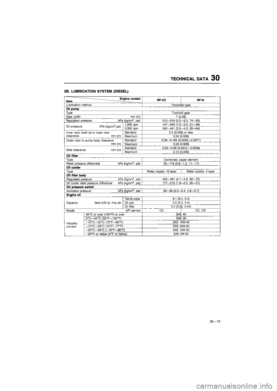
2B. LUBRICATION SYSTEM (DIESEL)
Engine moded Item RF-CX RF-N
Lubrication method Force-fed type
Oil pump
Type Trochoid gear
Gear width
mm
(in) 7 (0.28)
Regulated pressure kPa (kg/cm2,
psi)
510-618 (5.2-6.3, 74-90)
Oil pressure kPa (kg/cm2,psi) 1,000 rpm 147-245 (1.5-2.5, 21-36) Oil pressure kPa (kg/cm2,psi) 3,000 rpm 343—441 (3.5—4.5, 50—64)
Inner rotor tooth
tip to
outer rotor clearance
mm
(in)
Standard 0.2 (0.008)
or
less Inner rotor tooth
tip to
outer rotor clearance
mm
(in) Maximum 0.24 (0.009)
Outer rotor
to
pump body clearance
mm (in)
Standard 0.09-0.184 (0.0035-0.0071) Outer rotor
to
pump body clearance
mm (in) Maximum 0.22 (0.009)
Side clearance
mm
(in) Standard 0.03-0.09 (0.0012-0.0036) Side clearance
mm
(in) Maximum 0.14 (0.006)
Oil filter
Type Combined, paper element
Relief pressure differential kPa (kg/cm2,
psi)
78-118 (0.8-1.2, 11-17)
Oil cooler
Type Water cooled,
10
layer Water cooled,
4
layer
Oil filter body
Regulated pressure kPa (kg/cm2,
psi)
402-481 (4.1-4.9, 58—70)
Oil cooler relief pressure differential kPa (kg/cm2,
psi)
177-216 (1.8-2.2, 26-31)
Oil pressure switch
Activation pressure kPa (kg/cm2,
psi)
20-39 (0.2—0.4, 2.8-5.7)
Engine oil
Capacity liters (US qt, Imp
qt)
Total (drv enaine) 6.1 (6.4, 5.4)
Capacity liters (US qt, Imp
qt)
Oil pan 5.0 (5.3, 4.4) Capacity liters (US qt, Imp
qt)
Oil filter 0.5 (0.52, 0.44)
Grade API service CC CC,
CD
Viscosity number
40°C
or
over (104°F)
or
over SAE
40
Viscosity number
0°C—40°C (32°F—100°F) SAE
30
Viscosity number
-10°C—35°C (15°F—90°F) SAE 15W-40 Viscosity number -10°C—25°C (15°F—77°F) SAE 20W-20 Viscosity number
-25°C—30°C (-18°F—86°F) SAE 10W-30
Viscosity number
-20°C
or
below (4°F
or
below) SAE 5W-30
30—15
Page 1840 of 1865
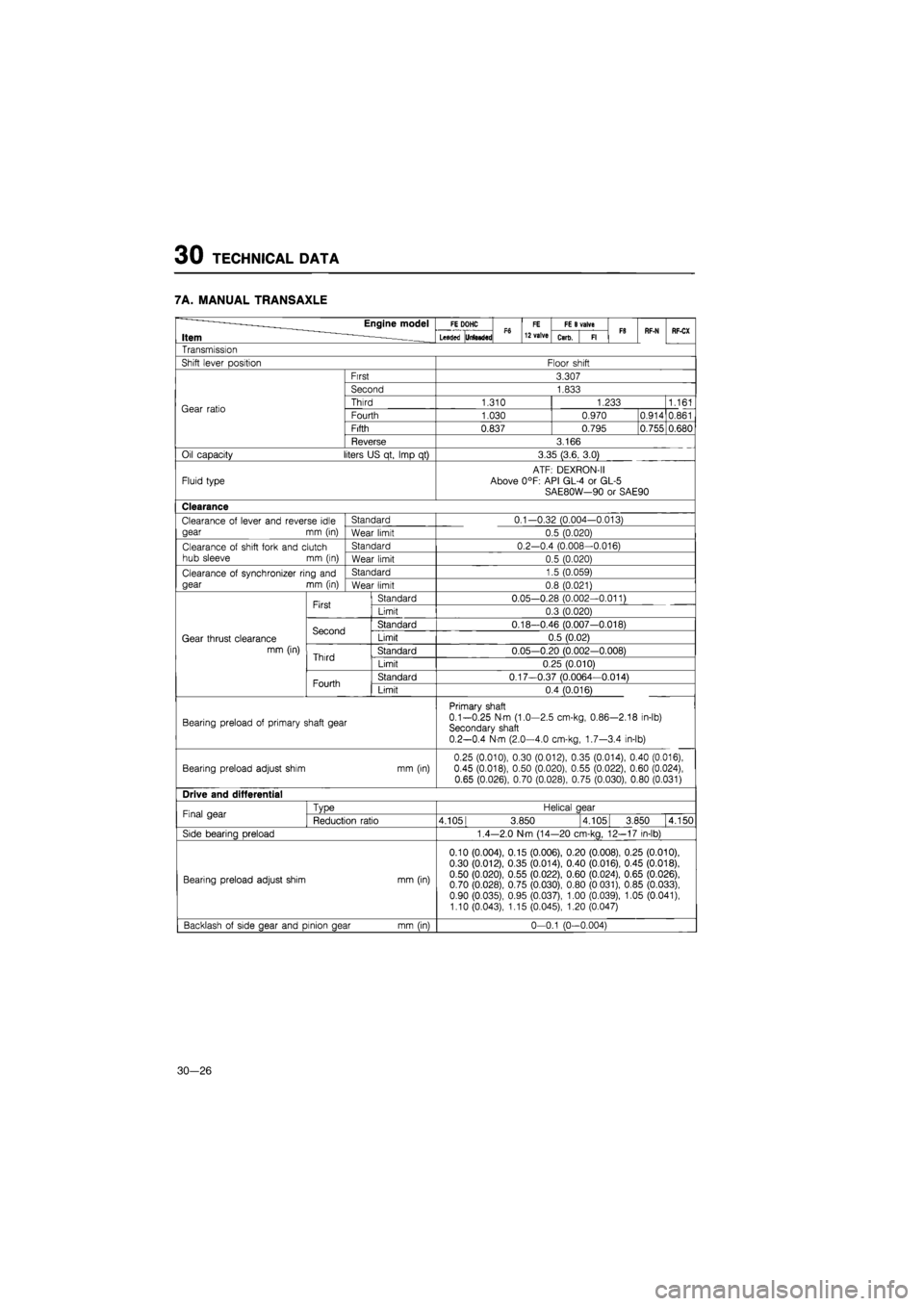
30 TECHNICAL DATA
7A. MANUAL TRANSAXLE
Engine model FE DOHC Ffl FE FE
B
valve F8 Item —— Leaded UriBsded Ffl 12 valve Carb. Fl F8 RF-N RF-CX
Transmission
Shift
lever
position Floor shift
Gear ratio
First 3.307
Second 1.833
Third 1.310
Fourth 1.030
Fifth 0.837
1,233
0.970
0.795
0.914
1.161
0.861
0.755 0.680
Reverse 3.166
Oil capacity liters US qt, Imp
qt)
3.35 (3.6, 3.0)
Fluid type
ATF: DEXRON-II
Above 0°F: API GL-4
or
GL-5
SAE80W—90
or
SAE90
Clearance
Clearance
of
lever and reverse idle
gear
mm (in)
Standard 0.1—0.32 (0.004-0.013) Clearance
of
lever and reverse idle
gear
mm (in)
Wear limit 0.5 (0.020)
Clearance
of
shift fork and clutch hub sleeve
mm (in)
Standard 0.2—0.4 (0.008-0.016) Clearance
of
shift fork and clutch hub sleeve
mm (in)
Wear limit 0.5 (0.020)
Clearance
of
synchronizer ring
and
gear
mm
(in)
Standard 1.5 (0.059) Clearance
of
synchronizer ring
and
gear
mm
(in) Wear limit 0.8 (0.021)
Gear thrust clearance
mm (in)
First Standard 0.05—0.28 (0.002-0.011)
Gear thrust clearance
mm (in)
First Limit 0.3 (0.020)
Gear thrust clearance
mm (in)
Second Standard 0.18—0.46 (0.007-0.018)
Gear thrust clearance
mm (in)
Second Limit 0.5 (0.02) Gear thrust clearance
mm (in) Third Standard 0.05-0.20 (0.002-0.008)
Gear thrust clearance
mm (in) Third Limit 0.25 (0.010)
Gear thrust clearance
mm (in)
Fourth Standard 0.17—0.37 (0.0064—0.014)
Gear thrust clearance
mm (in)
Fourth Limit 0.4 (0.016)
Bearing preload
of
primary shaft gear
Primary shaft
0.1-0.25 N-m (1.0-2.5 cm-kg, 0.86-2.18 in-lb) Secondary shaft 0.2-0.4 N-m (2.0—4.0 cm-kg, 1.7-3.4 in-lb)
Bearing preload adjust shim mm (in) 0.25 (0.010), 0.30 (0.012), 0.35 (0.014), 0.40 (0.016), 0.45 (0.018), 0.50 (0.020), 0.55 (0.022), 0.60 (0.024), 0.65 (0.026), 0.70 (0.028), 0.75 (0.030), 0.80 (0.031)
Drive and differential
Final gear
TvDe
Reduction ratio
Side
bearina Dreload
Helical aear
4.1051 3.850 4.1051 3.850
4.150
1.4-2.0 N
m
(14—20 cm-kg, 12-17 in-lb)
Bearing preload adjust shim mm (in)
0.10 (0.004), 0.15 (0.006), 0.20 (0.008), 0.25 (0.010), 0.30 (0.012), 0.35 (0.014), 0.40 (0.016), 0.45 (0.018), 0.50 (0.020), 0.55 (0.022), 0.60 (0.024), 0.65 (0.026), 0.70 (0.028), 0.75 (0.030), 0.80 (0.031), 0.85 (0.033), 0.90 (0.035), 0.95 (0.037), 1.00 (0.039), 1.05 (0.041), 1.10 (0.043), 1.15 (0.045), 1.20 (0.047)
Backlash
of
side aear and
Dinion
aear mm (in) 0-0.1 (0-0.004)
30—26
Page 1846 of 1865
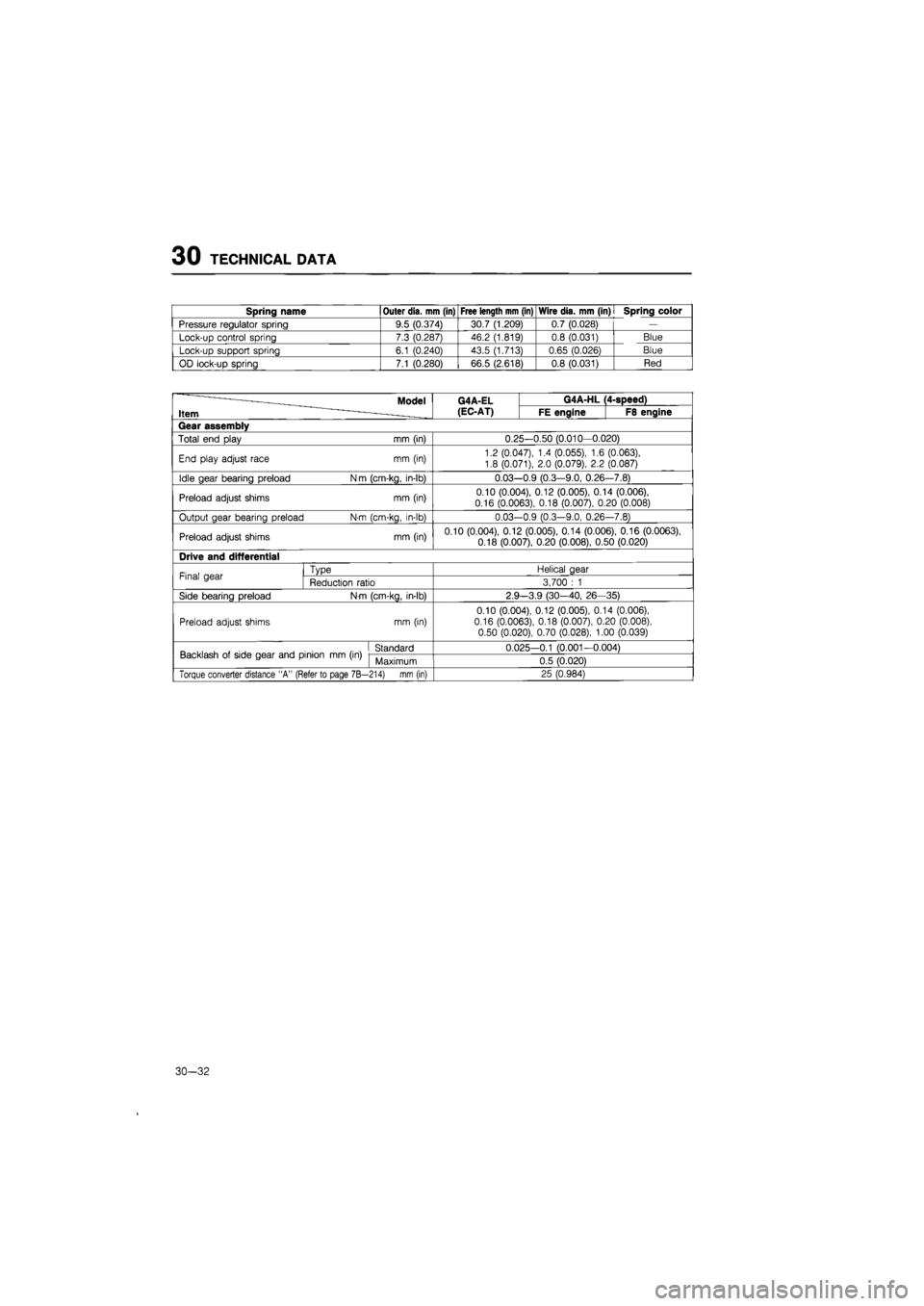
30 TECHNICAL DATA
Spring name Outer dia. mm (in) Free length mm (in) Wire dia. mm (in)
I
Spring color
Pressure regulator spring 9.5 (0.374) 30.7 (1.209) 0.7 (0.028)
—
Lock-up control spring 7.3 (0.287) 46.2 (1.819) 0.8 (0.031) Blue
Lock-up support spring 6.1 (0.240) 43.5 (1.713) 0.65 (0.026) Blue
OD lock-up spring 7.1 (0.280) 66.5 (2.618) 0.8 (0.031) Red
Model G4A-EL G4A-HL 4-speed)
Item (EC-AT) FE engine F8 engine
Gear assembly
Total end play mm (in) 0.25-0.50 (0.010-0.020)
End play adjust race mm (in) 1.2 (0.047),
1.4
(0.055),
1.6
(0.063),
1.8 (0.071), 2.0 (0.079),
2.2
(0.087)
Idle gear bearing preload N
m
(cm-kg, in-lb) 0.03--0.9 (0.3—9.0, 0.26 -7.8)
Preload adjust shims mm (in) 0.10 (0.004), 0.12 (0.005), 0.14 (0.006), 0.16 (0.0063), 0.18 (0.007), 0.20 (0.008)
Output gear bearing preload N-m (cm-kg, in-lb) 0.03--0.9 (0.3—9.0, 0.26 -7.8)
Preload adjust shims mm (in) 0.10 (0.004), 0.12 (0.005), 0.14 (0.006), 0.16 (0.0063),
0.18 (0.007), 0.20 (0.008), 0.50 (0.020)
Drive and differential
Final gear Type Helical gear Final gear Reduction ratio 3,700
: 1
Side bearing preload N-m (cm-kg, in-lb) 2.9 —3.9 (30-40,
26-
35)
Preload adjust shims mm (in)
0.10 (0.004), 0.12 (0.005), 0.14 (0.006), 0.16 (0.0063), 0.18 (0.007), 0.20 (0.008), 0.50 (0.020), 0.70 (0.028), 1.00 (0.039)
Backlash
of
side gear and pinion
mm (in)
Standard 0.025-0.1 (0.001-0.004) Backlash
of
side gear and pinion
mm (in)
Maximum 0.5 (0.020)
Torque converter distance "A" (Refer to page 7B— 214) mm (in) 25 (0.984)
30-32
Page 1849 of 1865
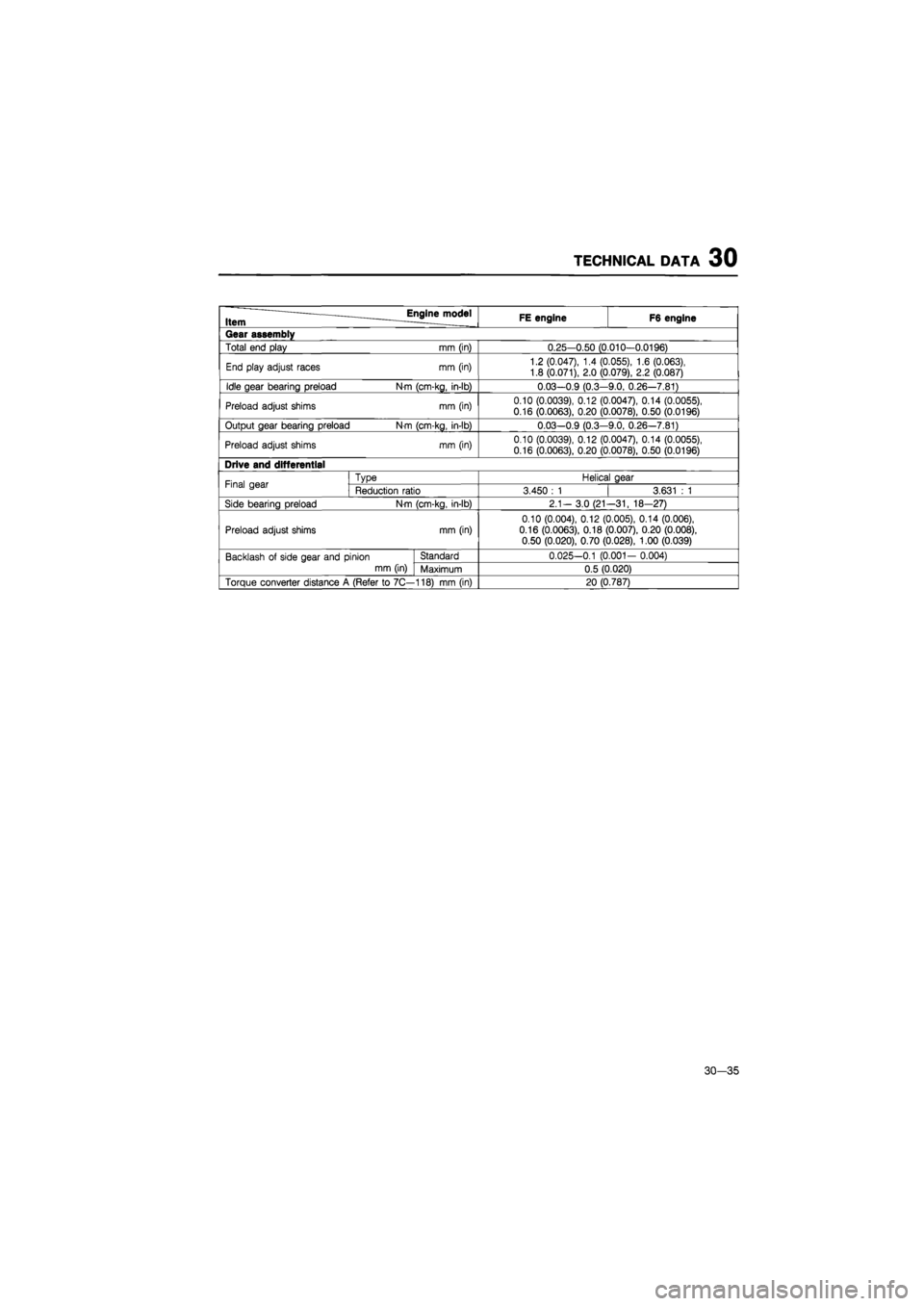
TECHNICAL DATA 30
Item Englnejnodel FE engine F6 engine
Gear assembly
Total end play mm (in) 0.25-0.50 (0.010-0.0196)
End play adjust races mm (in) 1.2 (0.047), 1.4 (0.055), 1.6 (0.063), 1.8 (0.071), 2.0 (0.079), 2.2 (0.087)
Idle gear bearing preload N-m (cm-kg, in-lb) 0.03—0.9 (0.3-9.0, 0.26—7.81)
Preload adjust shims mm (in) 0.10 (0.0039), 0.12 (0.0047), 0.14 (0.0055), 0.16 (0.0063), 0.20 (0.0078), 0.50 (0.0196)
Output gear bearing preload Nm (cm-kg, in-lb) 0.03-0.9 (0.3-9.0, 0.26-7.81)
Preload adjust shims mm (in) 0.10 (0.0039), 0.12 (0.0047), 0.14 (0.0055),
0.16 (0.0063), 0.20 (0.0078), 0.50 (0.0196)
Drive and differential
Final gear Type Helical gear Final gear Reduction ratio 3.450
: 1
3.631
: 1
Side bearing preload Nm (cm-kg, in-lb) 2.1- 3.0 (21 -31, 18-27)
Preload adjust shims mm (in) 0.10 (0.004), 0.12 (0.005), 0.14 (0.006), 0.16 (0.0063), 0.18 (0.007), 0.20 (0.008), 0.50 (0.020), 0.70 (0.028), 1.00 (0.039)
Backlash
of
side gear and pinion Standard 0.025-0.1 (0.001- 0.004)
mm (in) Maximum 0.5 (0.020)
Torque converter distance
A
(Refer
to
7C— 118) mm (in) 20 (0.787)
30-35