Page 1194 of 1865
7C INSPECTION AND REPAIR
76G07C-213
86U07B-325
Roll pin
To remove the roll pin from the pinion shaft, place
the gear case on a vise and knock the pin out with
a suitable pin punch (04.0 mm (0.157 in) ) and
hammer.
Note
a) Use the protective plates in the vice to pre-
vent damage to the differential.
b) Insert the punch into the roll pin hole from
the ring gear side.
Side bearing inner race
1. Remove the side bearing inner race (side oppo-
site the ring gear) from the gear case with the SST.
2. Remove the side bearing inner race (ring gear side)
with a combination of parts from the SST.
86U07B-326
Inspection
Check the following and replace any faulty parts.
1. Damaged or worn gears
2. Cracked or damaged gear case
3. Damaged bearings
86U07B-327
7C-80
Page 1196 of 1865
7C INSPECTION AND REPAIR
•Jo V-sVOJ
V-^ sy \
^ I
Dial indicator
Pinion gear
A
86U07B-332
6. Install the thrust washers and side gears into the
gear case at the same time, then turn them back
on the pinion gear and align them with the pinion
shaft hole.
7. Check and adjust the backlash of the side gears
and pinion gears as follows:
(1) Install the left and right driveshafts in the
differential assembly.
(2) Support the driveshafts on V-blocks.
(3) Measure the backlash of both pinion gears.
Backlash:
Standard 0.025—0.1 mm (0.001—0.004 in)
Maximum 0.5 mm (0.020 in)
8.
If
the backlash is not within specification, place the
differential assembly.
86U07B-333
OUTPUT GEAR
Disassembly
Disassemble in the sequence shown in the figure, referring to the disassembly note for specially marked
parts.
1. Output gear
bearing
2. Output gear
bearing
3. Output gear
76G07C-214
7C—82
Page 1208 of 1865
7C ASSEMBLY
3. Adjust the differential side bearing preload and select the adjust shim(s) as described below.
Note
To inspect and adjust the preload, use the SST shown below.
76G07C-242
(1) Remove the side bearing housing race and ad-
just shims from the transaxle case. (Refer to
page 7C—88.)
(2) Set the differential assembly into the convert-
er housing.
(3) Install the outer race removed in step (1) into
the SST; then set them on the differential as-
sembly.
Caution
Eliminate the gap by turning either A or B of
the selector.
7C-94
Page 1210 of 1865

7C ASSEMBLY
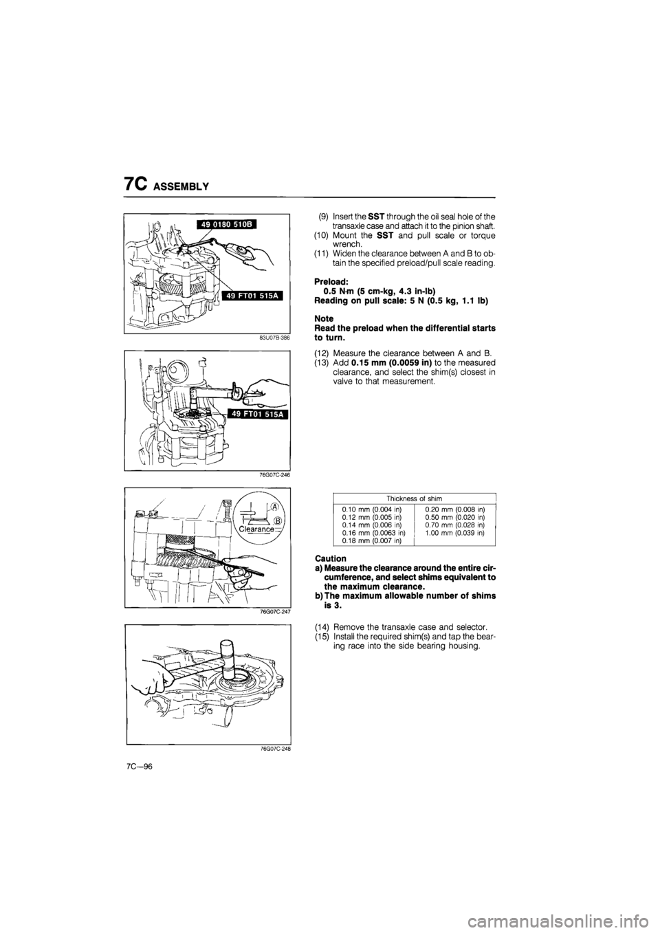
(9) Insert the SST through the oil seal hole of the
transaxle case and attach
it
to the pinion shaft.
(10) Mount the SST and pull scale or torque
wrench.
(11) Widen the clearance between A and B to ob-
tain the specified preload/pull scale reading.
Preload:
0.5 N-m (5 cm-kg, 4.3 in-lb)
Reading on pull scale: 5 N (0.5 kg, 1.1 lb)
Note
Read the preload when the differential starts
to turn.
(12) Measure the clearance between A and B.
(13) Add 0.15 mm (0.0059 in) to the measured
clearance, and select the shim(s) closest in
valve to that measurement.
76G07C-246
Thickness
of
shim
0.10
mm
(0.004
in)
0.12
mm
(0.005
in)
0.14
mm
(0.006
in)
0.16
mm
(0.0063
in)
0.18 mm (0.007
in)
0.20 mm (0.008
in)
0.50 mm (0.020
in)
0.70
mm
(0.028
in)
1.00 mm (0.039
in)
76G07C-247
Caution
a) Measure the clearance around the entire cir-
cumference, and select shims equivalent to
the maximum clearance.
b)The maximum allowable number of shims
is 3.
(14) Remove the transaxle case and selector.
(15) Install the required shim(s) and tap the bear-
ing race into the side bearing housing.
76G07C-248
7C-96
Page 1221 of 1865
ASSEMBLY 7C
76G07C-279
76G07C-280
76G07C-281
Procedure
1. Install the governor assembly.
(1) Mount the governor along with a new gasket
onto the transaxle case so that the sleeve
projection is aligned with the alignment mark
on the transaxle case.
(2) Install the governor cover along with a new
gasket.
Tightening torque:
8—11 N-m (80—110 cm-kg, 69—95 in-lb)
2. Apply a thin coat of silicone sealant to the contact
surfaces of the converter housing and transaxle
case.
3. Install the transaxle case onto the converter
housing.
Tightening torque:
29—46 N-m (3.0—4.7 m-kg, 22—34 ft-lb)
4. Install the SST into the differential side gear.
Caution
Failure to install the SST may allow the
differential side gears to become misaligned.
76G07C-282
7C-107
Page 1236 of 1865

7C INSTALLATION
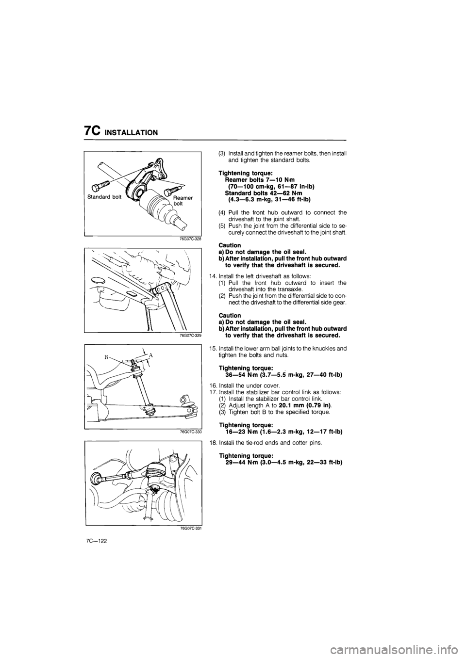
(3) Install and tighten the reamer bolts, then install
and tighten the standard bolts.
Tightening torque:
Reamer bolts 7—10 N-m
(70—100 cm-kg, 61—87 in-lb)
Standard bolts 42—62 N m
(4.3—6.3 m-kg, 31—46 ft-lb)
(4) Pull the front hub outward to connect the
driveshaft to the joint shaft.
(5) Push the joint from the differential side to se-
curely connect the driveshaft to the joint shaft.
Caution
a) Do not damage the oil seal.
b) After installation, pull the front hub outward
to verify that the driveshaft is secured.
Install the left driveshaft as follows:
(1) Pull the front hub outward to insert the
driveshaft into the transaxle.
(2) Push the joint from the differential side to con-
nect the driveshaft to the differential side gear.
Caution
a) Do not damage the oil seal.
b) After installation, pull the front hub outward
to verify that the driveshaft is secured.
Install the lower arm ball joints to the knuckles and
tighten the bolts and nuts.
Tightening torque:
36—54 N-m (3.7—5.5 m-kg, 27—40 ft-lb)
Install the under cover.
Install the stabilizer bar control link as follows:
(1) Install the stabilizer bar control link.
(2) Adjust length A to 20.1 mm (0.79 in).
(3) Tighten bolt B to the specified torque.
Tightening torque:
16—23 N-m (1.6—2.3 m-kg, 12—17 ft-lb)
Install the tie-rod ends and cotter pins.
Tightening torque:
29—44 N-m (3.0—4.5 m-kg, 22—33 ft-lb)
7C-122
Page 1251 of 1865
9 OUTLINE
OUTLINE
STRUCTURAL VIEW
Driveshaft (MTX)
86U09X-080
1. Lock nut
2. Shaft and ball joint as-
sembly
3. Boot
4. Boot band
5. Ball joint assembly
(differential side)
6. Snap ring
7. Clip
8. Clip
9. Joint shaft assembly
10. Reamer bolt
11. Bracket mounting bolt
9—2
Page 1279 of 1865
9 DRIVESHAFT
86U09X-055
86U09X-056
Driveshaft
Disconnect the driveshaft from the transaxle with a
prybar.
Note
Do not damage the boot or the oil seal.
Joint shaft
As shown in the figure, insert a pry bar between the
driveshaft and the joint shaft and tap on the bar to
uncouple them.
Front wheel hub
Use the SST to push the shaft out if it is stuck in the
front wheel hub.
86U09X-057
Differential
Install the SST to hold the side gear after removing
the driveshaft.
86U09X-058
9—30