1987 MAZDA 626 checking oil
[x] Cancel search: checking oilPage 701 of 1865

o
GO o
VE-TYPE RF79 13 800A: 104748-0343 For RF-N ENGINE
£ TEST OIL SAE Standard test oil (SEA 967C)
Fuel injection amount Chamber pressure and timer stroke Load sensing timer and overflowing quantity Measurenment
Item Pump speed (RPM)
Fuel injection amount
(cm3/stroke)
Start 100 More than 42/1,000
Full load
600 29.0—33.0/1,000
Full load
1.375 34.9—36.9/1,000
Full load 2,325 30 2—34.2/1,000 Full load
2,600 9.8—15 8/1,000
Full load
2,700 Max. 6 0/1,000
Idling 360 8-12/1,000
Pump speed (RPM) Chamber pressure
(kg/cm2)
Timer stroke
(mm)
600 2 2—2.8
1,375 4 4—5,0 3 9—4.5
1,800 5 6—6.2 6.1-7.3
2.325 6.9—7.5 7.2—8.4
Item Fuel injectioon amount
(cm3/stroke)
Load sens- Start 26.7-29.7/1,000
ing timer End 14.6—17.6/1,000
Overflowing quantity 46.3—90.3/1.000
'Checking condition
Pump speed: 1,375 rpm
Lever: Full load
Measuring place Dimension (mm)
KF 5.8—5.9
K 3.2—3 4
MS 1.4—1.6
c
o'
3 03 3 o c 3
O 3
o o o
o
CD
50
40
30
20
10
r
10
100 600
o o
1,375 1,800
Injection pump speed RPM
2,325 2,600 2,700
H -D
u -1 T3 52. ° ? T1
CD (0 (A c ®
"3? CD o" 3
(D O r* o 3
u C 3 "O
O 3" 0) ^ 0> o CO
a o
3 •n
m i-
co •<
(/> H m
Page 707 of 1865

5
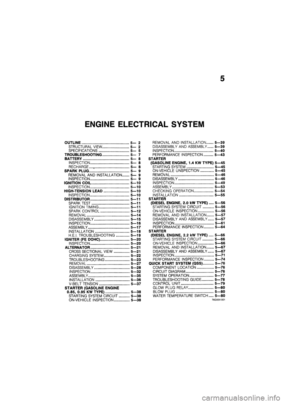
ENGINE ELECTRICAL SYSTEM
OUTLINE 5— 2
STRUCTURAL VIEW 5— 2
SPECIFICATIONS 5— 5
TROUBLESHOOTING 5— 7
BATTERY 5— 8
INSPECTION 5— 8
RECHARGE. 5— 8
SPARK PLUG 5— 9
REMOVAL AND INSTALLATION 5— 9
INSPECTION 5— 9
IGNITION COIL 5—10
INSPECTION 5—10
HIGH-TENSION LEAD 5—10
INSPECTION 5—10
DISTRIBUTOR 5—11
SPARK TEST 5—11
IGNITION TIMING 5—11
SPARK CONTROL 5—12
REMOVAL 5—14
DISASSEMBLY 5—15
INSPECTION 5—16
ASSEMBLY 5—17
INSTALLATION 5—18
H.E.I. TROUBLESHOOTING 5—19
IGNITER (FE DOHC) 5—20
INSPECTION 5—20
ALTERNATOR 5—21
CROSS SECTIONAL VIEW 5—21
CHARGING SYSTEM 5—22
TROUBLESHOOTING 5—23
REMOVAL 5—27
DISASSEMBLY 5—28
INSPECTION 5—32
ASSEMBLY 5—35
INSTALLATION 5—36
V-BELT TENSION 5—37
STARTER (GASOLINE ENGINE
0.85, 0.95 KW TYPE) 5—38
STARTING SYSTEM CIRCUIT 5—38
ON-VEHICLE INSPECTION 5—38
REMOVAL AND INSTALLATION 5—39
DISASSEMBLY AND ASSEMBLY 5—39
INSPECTION 5—40
PERFORMANCE INSPECTION 5—43
STARTER
(GASOLINE ENGINE, 1.4 KW TYPE) 5—45
STARTING SYSTEM 5—45
ON-VEHICLE UNSPECTION 5—45
REMOVAL 5—46
DISASSEMBLY 5—46
INSPECTION 5—49
ASSEMBLY 5—53
CHECKING OPERATION 5—54
INSTALLATION 5—55
STARTER
(DIESEL ENGINE, 2.0 kW TYPE) .... 5—56
STARTING SYSTEM CIRCUIT 5—56
ON-VEHICLE INSPECTION 5—56
REMOVAL AND INSTALLATION 5—57
DISASSEMBLY AND ASSEMBLY 5—57
INSPECTION 5—61
PERFORMANCE INSPECTION 5—64
STARTER
(DIESEL ENGINE, 2.2 kW TYPE).... 5—66
STARTING SYSTEM CIRCUIT 5—66
ON-VEHICLE INSPECTION 5—66
REMOVAL AND INSTALLATION 5—67
DISASSEMBLY AND ASSEMBLY 5—67
INSPECTION 5—71
PERFORMANCE INSPECTION 5—74
QUICK START SYSTEM (QSS) 5-76
COMPONENT LOCATION 5—76
CIRCUIT DIAGRAM 5—76
SYSTEM OPERATION 5—77
TROUBLESHOOTING GUIDE 5—78
CONTROL UNIT 5—79
GLOW PLUG RELAY 5—80
BLOW PLUG 5—80
WATER TEMPERATURE SWITCH.... 5—80
76g05x-001
Page 747 of 1865

STARTER (GASOLINE ENGINE, 0.85, 0.95 KW TYPE) 5
4BG05X-082
4BG05X-083
4BG05X-084
2. Vibration of the commutator
(1) Place the armature on V blocks, and measure
the vibration by using a dial gauge.
(2) If the vibration is Limit or more, repair so that
it becomes standard by using a lathe, or re-
place the armature.
Standard vibration: 0.05 mm (0.002 in)
Limit: 0.4 mm (0.018 in)
Note
Before checking, be sure that there is no play
in the bearings.
3. Outer diameter of the commutator
Replace the armature if the outer diameter of the
commutator is grind limit or less.
4. Roughness of the commutator surface
(1) If the commutator surface is dirty, wipe it with
a cloth.
(2) If it is rough, repair it by using a lathe or fine
sandpaper.
Grind limit: 31 mm (1.22 in)
5. Segment groove depth
If the depth of the mold between segments is limit
depth or less, undercut the grooves by standard
depth.
Standard depth:
0.5—0.8 mm (0.020—0.031 in)
Limit depth: 0.2 mm (0.008 in)
Field Coil
1. Wiring damage
(1) Check for continuity between the connector
and brushes by using a circuit tester.
(2) Replace the yoke assembly if there is no con-
tinuity.
4BG05X-085
5—41
Page 768 of 1865

5 STARTER (DIESEL ENGINE, 2.0 KW TYPE)
4BG05X-082
4BG05X-103
Faulty repair
Bad Good
Mica
Undercut
Segments
4BG05X-084
2. Vibration of the commutator
(1) Place the armature on V blocks, and measure
the vibration by using a dial gauge.
(2) If the vibration is Limit or more, repair so that
it becomes standard by using a lathe, or re-
place the armature.
Standard vibration: 0.05 mm (0.002 in)
Limit: 0.4 mm (0.018 in)
Note
Before checking, be sure that there is no play
in the bearings.
3. Outer diameter of the commutator
Replace the armature if the outer diameter of the
commutator is grind limit or less.
4. Roughness of the commutator surface
(1) If the commutator surface is dirty, wipe it with
a cloth.
(2) If it is rough, repair it by using a lathe or fine
sandpaper.
Grind limit: 34 mm (1.34 in)
5. Segment groove depth
If the depth of the mold between segments is limit
depth or less, undercut the grooves by standard
depth.
Standard depth:
0.5—0.8 mm (0.020—0.031 in)
Limit depth: 0.2 mm (0.008 in)
Field Coil
1. Wiring damage
(1) Check for continuity between the connector
and brushes by using a circuit tester.
(2) Replace the yoke assembly if there is no con-
tinuity.
4BG05X-085
5-62
Page 777 of 1865

STARTER (DIESEL ENGINE, 2.2 KW TYPE) 5
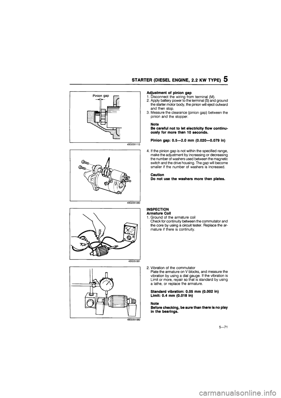
4BG05X-113
4BG05X-080
Adjustment of pinion gap
1. Disconnect the wiring from terminal (M).
2. Apply battery power to the terminal (S) and ground
the starter motor body, the pinion will eject outward
and then stop.
3. Measure the clearance (pinion gap) between the
pinion and the stopper.
Note
Be careful not to let electricity flow continu-
ously for more than 10 seconds.
Pinion gap: 0.5—2.0 mm (0.020—0.079 in)
4. If the pinion gap is not within the specified range,
make the adjustment by increasing or decreasing
the number of washers used between the magnetic
switch and the drive housing. The gap will become
smaller if the number of washers is increased.
Caution
Do not use the washers more than plates.
INSPECTION
Armature Coil
1. Ground of the armature coil
Check for continuity between the commutator and
the core by using a circuit tester. Replace the ar-
mature if there is continuity.
4BG05-081
2. Vibration of the commutator
Plate the armature on V blocks, and measure the
vibration by using a dial gauge. If the vibration is
Limit or more, repair so that is standard by using
a lathe, or replace the armature.
Standard vibration: 0.05 mm (0.002 in)
Limit: 0.4 mm (0.018 in)
Note
Before checking, be sure than there is no play
in the bearings.
4BG05X-Q82
5-71
Page 879 of 1865

TROUBLESHOOTING (G4A-EL) 7B
By following the above seven steps, the cause of the problem should be located.
As another guide to faster location of the causes of problems, the Quick Diagnosis Chart is included
at pages 7B—13, 14.
In this chart, a circle is used to indicate the components that might be the cause of trouble for 23
types of problems. It is only necessary to check those components indicated by circles, at each step
cf the troubleshooting process, in order to quickly locate the cause of the problem.
Quick Diagnosis Chart
The Quick Diagnosis Chart shows various problems and the relationship of various components that
might be the cause of the problem.
1. Components indicated in the "Self-Diag." column are diagnosed by the EC-AT control unit self-
diagnosis function.
The EC-AT Tester can be used for easy retrieval of these signals.
2. Components indicated in the "Adjustment" column indicate that there is a possibility that the prob-
lem may be the result of an incorrect adjustment.
Check the adjustment of each component, and readjust if necessary.
3. Input and outout signals of the EC-AT control unit for the components indicated in the "EC-AT
TESTER" column can be easily checked by using of the EC-AT Tester.
4. Components indicated in the "Stall Test" column can be checked for malfunction by the results
of the stall test.
5. Components indicated in the "Time Lag Test" column can be checked for malfunction by the results
of the time lag test.
6. Components indicated in the "Oil Pressure Test" column can be checked for malfunction by the
results of the oil pressure test.
7. Components indicated in the "Road Test" column can be checked for malfunction by the results
of the road test.
8. The checking, adjusting, repair or replacement procedures for each component is described in the
page(s) noted in the "Reference Page" column.
7B—13
Page 897 of 1865

TROUBLESHOOTING (G4A-EL) 7B
STEP 6 (OIL PRESSURE TEST)
This step checks line pressures for checking the hydraulic components and for oil leakage.
Line Pressure Test
Preparation
1. Perform the preparation procedure shown in STEP 4 (STALL TEST).
2. Connect a tachometer to the engine.
3. Connect the SST to the line pressure inspection hole (square head plug L)
Procedure
76G07B-031
1. Start the engine and check the idle speed in P range
Idle speed: 900 -so rpm
2. Shift the selector lever to D range and read the line pressure at idle.
3. Depress the brake pedal firmly with the left foot and gradually depress the accelerator pedal with
the right foot.
4. Read the line pressure as soon as the engine speed becomes constant, then release the accelera-
tor pedal.
Caution
Steps 3 to 4 must be performed within 5 seconds.
5. Shift the selector lever to N range and run the engine at idle for at least one minute.
6. Read the line pressure at idle and engine stall speeds for each range in the same manner.
7B—31
Page 908 of 1865

7B TROUBLESHOOTING (G4A-HL)
Quick Diagnosis Chart
The Quick Diagnosis Chart shows various problems and the relationship of various components that
might be the cause of the problem.
The following is an explanation of the symbols used in this chart.
1. Components indicated in the "Adjustment" column indicate that there is a possibility that the prob-
lem may be the result of an incorrect adjustment.
Check the adjustment of each component, and readjust if necessary.
2. The components indicated in the "Electrical System Inspection" column can be checked for mal-
function by the results of the checking procedure.
3. Components indicated in the "Stall Test" column can be checked for malfunction by the results
of the stall test.
4. Components indicated in the "Time Lag Test" column can be checked for malfunction by the results
of the time lag test.
5. Components indicated in the "Road Test" column can be checked for malfunction by the results
of the road test.
6. Components indicated in the "Oil Pressure Test" column can be checked for malfunction by the
results of the oil pressure test.
7. The checking, adjusting, repair or replacement procedures for each component is described in the
page(s) noted in the "Reference Page" column.
76G07B-041
Inspection point
Item
Adjustment
Electrical System Inspection
Electrical control system
JO o
II in a> ZJ i 2 : o. 5 E - £ CD _
O §
o
o
Prelimi-nary
CD t/1 ro cd
O O
o
CD ro — o o u 0) CD CO
O
Hydraulic control system
cn "o w ~ CD ro .> -a 5 CD > cl o
5 O
3 a
3 6
o
Power train
O I h
£ ro o O LL O
o > CD (fl "D c ro sz CD o JJL. "3 ro o _Q •sT co C\J
ro ro 5 ? CD CD c c O O
Stall Test
Time Lag Test
O O o o o o o o o o
o o o o o o o o
Oil Pressure Test O o o o o o o o o o o
Road Test O o o o
7B—42