Page 1226 of 1865

7C ASSEMBLY
7C-112
Procedure
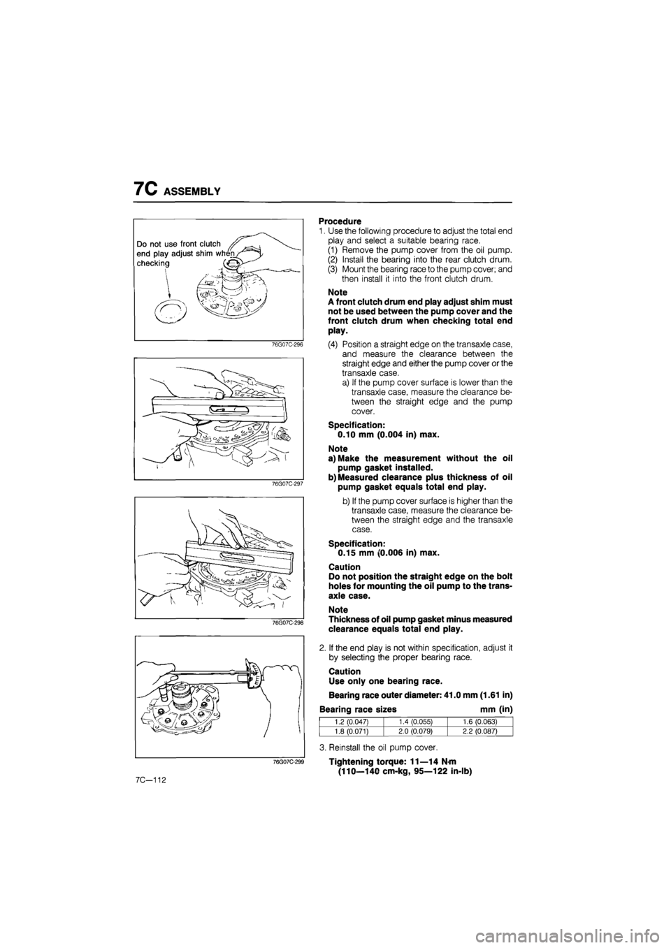
1. Use the following procedure to adjust the total end
play and select a suitable bearing race.
(1) Remove the pump cover from the oil pump.
(2) Install the bearing into the rear clutch drum.
(3) Mount the bearing race to the pump cover; and
then install it into the front clutch drum.
Note
A front clutch drum end play adjust shim must
not be used between the pump cover and the
front clutch drum when checking total end
play.
(4) Position a straight edge on the transaxle case,
and measure the clearance between the
straight edge and either the pump cover or the
transaxle case.
a) If the pump cover surface is lower than the
transaxle case, measure the clearance be-
tween the straight edge and the pump
cover.
Specification:
0.10 mm (0.004 in) max.
Note
a) Make the measurement without the oil
pump gasket installed.
b) Measured clearance plus thickness of oil
pump gasket equals total end play.
b) If the pump cover surface is higher than the
transaxle case, measure the clearance be-
tween the straight edge and the transaxle
case.
Specification:
0.15 mm (0.006 in) max.
Caution
Do not position the straight edge on the bolt
holes for mounting the oil pump to the trans-
axle case.
Note
Thickness of oil pump gasket minus measured
clearance equals total end play.
2. If the end play is not within specification, adjust it
by selecting the proper bearing race.
Caution
Use only one bearing race.
Bearing race outer diameter: 41.0 mm (1.61 in)
Bearing race sizes mm (in)
1.2 (0.047) 1.4 CO.055) 1.6 (0.063)
1.8 (0.071) 2.0 (0.079) 2.2 (0.087)
3. Reinstall the oil pump cover.
Tightening torque: 11—14 N-m
(110—140 cm-kg, 95—122 in-lb)
Page 1695 of 1865
15 WARNING AND SENDER
86U15X-068
86U15X069
86U15X-070
Door Switch
1. Check for continuity of the switch with an
ohmmeter.
2. If continuity is not as specified, replace the switch.
Washer Level Sensor
1. Check for continuity between C (LY) terminal and
D (B) terminal of the washer level sensor con-
nector.
Oil Pressure Switch
1. Disconnect the connector from the oil pressure
switch.
2. Check for continuity between the switch and a
body ground with each condition.
Coolant Level Sensor
1. Remove the level sensor and connect the con-
nector.
2. With the sensor not grounded to the body, start
the engine.
3. After checking that the warning light illuminates,
ground the threaded part of the sensor.
4. If the warning light remains illuminated, the sen-
sor is faulty and replace it.
73G15X-013
15—40
Engine Continuity
Running Yes
Stop No
Terminals Float level Continuity
C (LY)—D
(B)
Bottom Yes C (LY)—D
(B)
Above bottom No
2. If continuity is not as specified, replace the sensor.
Page 1739 of 1865

1 5 CRUISE CONTROL SYSTEM
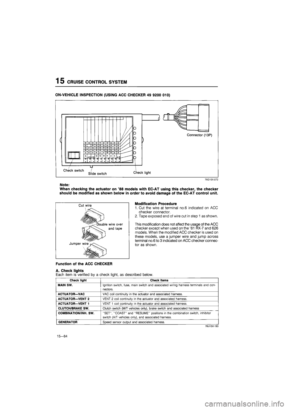
ON-VEHICLE INSPECTION (USING ACC CHECKER 49 9200 010)
76G15X-072
Note:
When checking the actuator on '88 models with EC-AT using this checker, the checker
should be modified as shown below in order to avoid damage of the EC-AT control unit.
Modification Procedure
1. Cut the wire at terminal no.6 indicated on ACC
checker connector.
2. Tape exposed end of wire cut in step 1 as shown.
This modification does not affect the usage of the ACC
checker except when used on the '81 RX-7 and 626
models. When the modified ACC checker is used on
these models, use a jumper wire and jump across
terminal no.6 to 3 indicated on ACC checker connec-
tor as shown.
Function of the ACC CHECKER
A. Check lights
Each item is verified by a check light, as described below.
Check light Check items
MAIN SW.
Ignition switch, fuse, main switch and associated wiring harness terminals and con-
nectors.
ACTUATOR—VAC
VAC coil continuity
in
the actuator and associated harness.
ACTUATOR—VENT 2
VENT
2
coil continuity
in
the actuator and associated harness.
ACTUATOR—VENT 1
VENT
1
coil continuity
in
the actuator and associated harness.
CLUTCH/BRAKE SW.
Clutch switch (M/T vehicles only), brake switch and associated harness
COMBINATION/INH. SW.
"SET", "COAST" and "RESUME" positions
in
the combination switch, inhibitor
switch (A/T vehicles only), and associated harness.
GENERATOR
Speed sensor output and associated harness.
76U15X-193
15-84
Page:
< prev 1-8 9-16 17-24