Page 45 of 1865

ON-VEHICLE INSPECTION 1 A
ON-VEHICLE INSPECTION
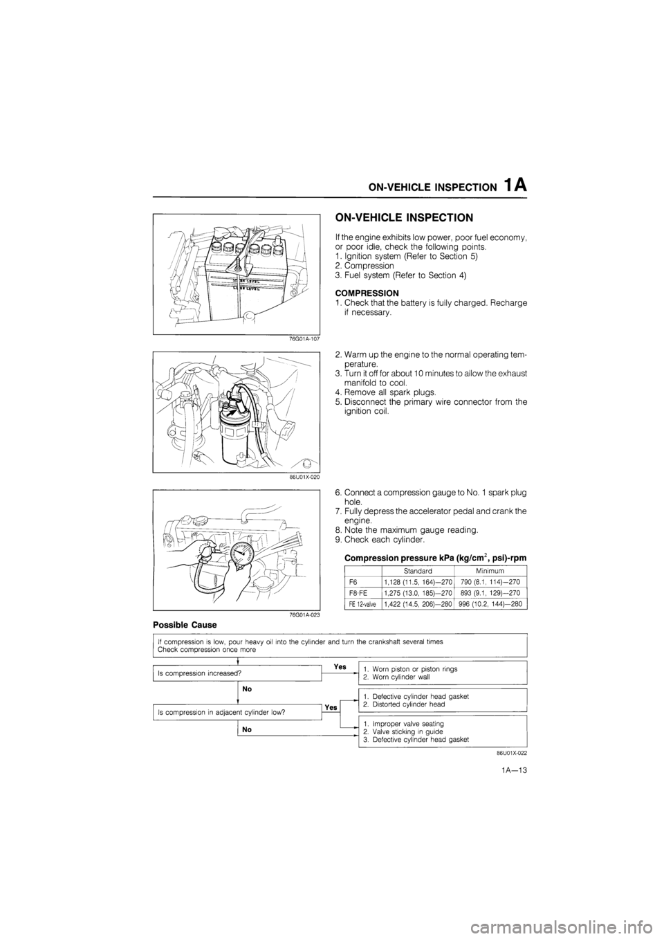
If the engine exhibits low power, poor fuel economy,
or poor idle, check the following points.
1. Ignition system (Refer to Section 5)
2. Compression
3. Fuel system (Refer to Section 4)
COMPRESSION
1. Check that the battery is fully charged. Recharge
if necessary.
76G01A-107
2. Warm up the engine to the normal operating tem-
perature.
3. Turn it off for about 10 minutes to allow the exhaust
manifold to cool.
4. Remove all spark plugs.
5. Disconnect the primary wire connector from the
ignition coil.
86U01X-020
6. Connect a compression gauge to No.
1
spark plug
hole.
7. Fully depress the accelerator pedal and crank the
engine.
8. Note the maximum gauge reading.
9. Check each cylinder.
Compression pressure kPa (kg/cm2, psi)-rpm
Standard Minimum
F6 1,128 (11.5, 164)—270 790 (8.1, 114)—270
F8-FE 1,275 (13.0, 185)—270 893 (9.1, 129)—270
FE 12-valve 1,422 (14.5, 206)—280 996 (10.2, 144)—280
76G01A-023
Possible Cause
86U01X-022
1A—13
Page 49 of 1865

ON-VEHICLE MAINTENANCE (TIMING BELT) 1 A
76G01A-027
76G01B-024
76G01A-028
/Jf
ry.
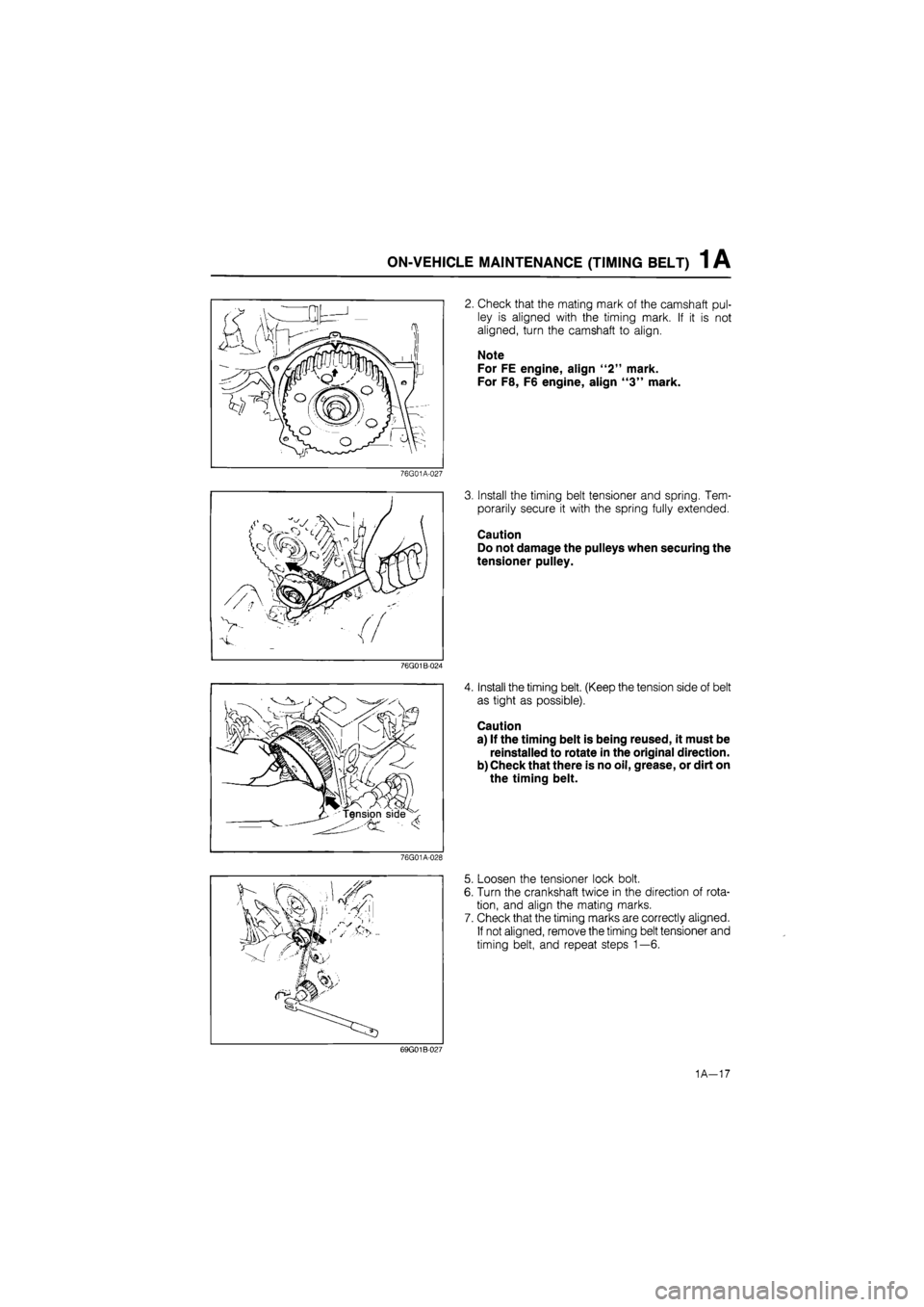
2. Check that the mating mark of the camshaft pul-
ley is aligned with the timing mark. If it is not
aligned, turn the camshaft to align.
Note
For FE engine, align "2" mark.
For F8, F6 engine, align "3" mark.
3. Install the timing belt tensioner and spring. Tem-
porarily secure it with the spring fully extended.
Caution
Do not damage the pulleys when securing the
tensioner pulley.
4. Install the timing belt. (Keep the tension side of belt
as tight as possible).
Caution
a) If the timing belt is being reused, it must be
reinstalled to rotate in the original direction.
b) Check that there is no oil, grease, or dirt on
the timing belt.
5. Loosen the tensioner lock bolt.
6. Turn the crankshaft twice in the direction of rota-
tion, and align the mating marks.
7. Check that the timing marks are correctly aligned.
If not aligned, remove the timing belt tensioner and
timing belt, and repeat steps 1—6.
69G01B-027
1A-17
Page 79 of 1865
DISASSEMBLY (CYLINDER BLOCK) 1 A
Main bearing cap
Before removing the main bearing caps, clean the
bearings, main journals, and caps, and measure the
following points.
1. Crankshaft end play. (Refer to page 1A—66.)
2. Main journal oil clearance. (Refer to page
1
A—65.)
76G01A-054
Pilot bearing (MTX)
Remove the pilot bearing from the crankshaft with the
SST.
86U01X-076
Piston and connecting rod
1. Before disassembling the piston and connecting
rod, check the oscillation torque as shown in the
figure.
If the large end does not drop by its own weight,
replace the piston or the piston pin.
79G01C-050
2. Remove the piston pin with the SST.
While removing the piston pin, check the pressure.
If it is lower than 5kN (500kg, 1,100 lb), replace
the piston pin or connecting rod.
76G01A-139
1A—47
Page 80 of 1865

INSPECTION AND REPAIR 1 A
INSPECTION AND REPAIR
1. Clean all parts, taking care to remove any gasket fragments, dirt, oil or grease, carbon, moisture
residue, or other foreign materials.
2. Inspect and repair must be performed in the order specified.
Caution
Be careful not to damage the joints or friction surfaces of aluminum alloy components (such
as the cylinder head or pistons).
86U01X-077
Cylinder Head
1. Inspect the cylinder head for damage, cracks, and
leakage of water or oil. Replace if necessary.
2. Measure the cylinder head distortion in the six
directions shown in the figure.
Distortion: 0.15 mm (0.006 in) max.
79G01C-106
If the cylinder head distortion exceeds specifica-
tion, grind the cylinder head surface.
If the cylinder head height is not within specifica-
tion, replace it.
Height:
91.95—92.05 mm (3.620—3.624 in)
Grinding limit: 0.20 mm (0.008 in) max.
Note
Before grinding the cylinder head, first check
the following. Replace if necessary.
• Sinking of valve seat
• Damage of manifold contact surface
• Camshaft oil clearance and end play
Measure the manifold contact surface distortion in
the six directions shown in the figure.
Distortion: 0.15 mm (0.006 in) max.
If distortion exceeds specification grind the surface
or replace the cylinder head.
79G01C-053
1A—48
Page 86 of 1865

INSPECTION AND REPAIR 1 A
mjjm
H D f IT~inr
86U01X-095
5. Measure the oil clearance of the camshaft and
camshaft caps.
(1) Remove any oil, or dirt from the journals and
bearing surface.
(2) Set the camshaft onto the cylinder head.
(3) Position plasti-gauge on top of the journals in
the axial direction.
(4) Place the camshaft caps and rocker arm shafts
in position, and tighten them to the specified
torque.
Tightening torque:
18—26
N
m (1.8—2.7 m-kg, 13—20 ft-lb)
(5) Remove the camshaft caps and measure the
oil clearance at each cap.
Oil clearance
Front and rear:
0.035—0.085 mm (0.0014—0.0033 in)
Center three journals:
0.065—0.115 mm (0.0026—0.0045 in)
Maximum: 0.15 mm (0.0059 in)
(6) If the oil clearance exceeds the maximum, re-
place the cylinder head.
86U01X-096
6. Measure the camshaft end play. If it exceeds the
maximum, replace the camshaft and/or the cylin-
der head.
End play:
0.08—0.16 mm (0.003—0.006 in)
Maximum: 0.20 mm (0.008 in)
86U01X-097
76G01A-131
1A—54
Rocker Arm and Rocker Arm Shaft
1. Check for wear or damage to the contact surface
of the rocker arm shaft and the rocker arm. Re-
place if necessary.
2. Check the oil clearance between the rocker arm
and shaft. Replace if necessary.
(1) Measure the rocker arm inner diameter.
Diameter:
19.000—19.033 mm (0.7480—0.7493 in)
...12-valve
16.000—16.027 mm (0.6299—0.6310 in)
... 8-valve
Page 87 of 1865

INSPECTION AND REPAIR 1 A
76G01A-065
76G01A-066
86U01X-100
(2) Measure the rocker arm shaft diameter.
Diameter:
18.959—18.980 mm (0.7464—0.7472 in)
...12 valve
15.966—15.984 mm (0.6286—0.6293 in)
... 8 valve
(3) Subtract the shaft diameter from the rocker arm
diameter.
Oil clearance mm (in)
Standard Maximum
12-valve 0.020-0.074
(0.0008-0.0029) 0.10 (0.0039)
8-valve 0.016-0.061 (0.0006-0.0024) 0.10 (0.0039)
Hydraulic Lash Adjuster (12-valve)
Check the HLA face for wear or damage. Replace
if necessary.
Caution
Do not remove the HLA unless necessary to
prevent damaging the O-ring.
Cylinder Block
1. Check the cylinder block. Repair or replace if
necessary.
(1) Leakage damage
(2) Cracks
(3) Scoring of wall
2. Measure the distortion of the top surface of the cyl-
inder block in the six directions as shown in the
figure.
Distortion: 0.15 mm (0.006 in) max.
3. If the distortion exceeds the maximum, repair by
grinding, or replace the cylinder block.
Grinding limit: 0.20 mm (0.008 in) max.
86U01X-117
1A—55
Page 89 of 1865

INSPECTION AND REPAIR 1A
76G01A-068
Piston
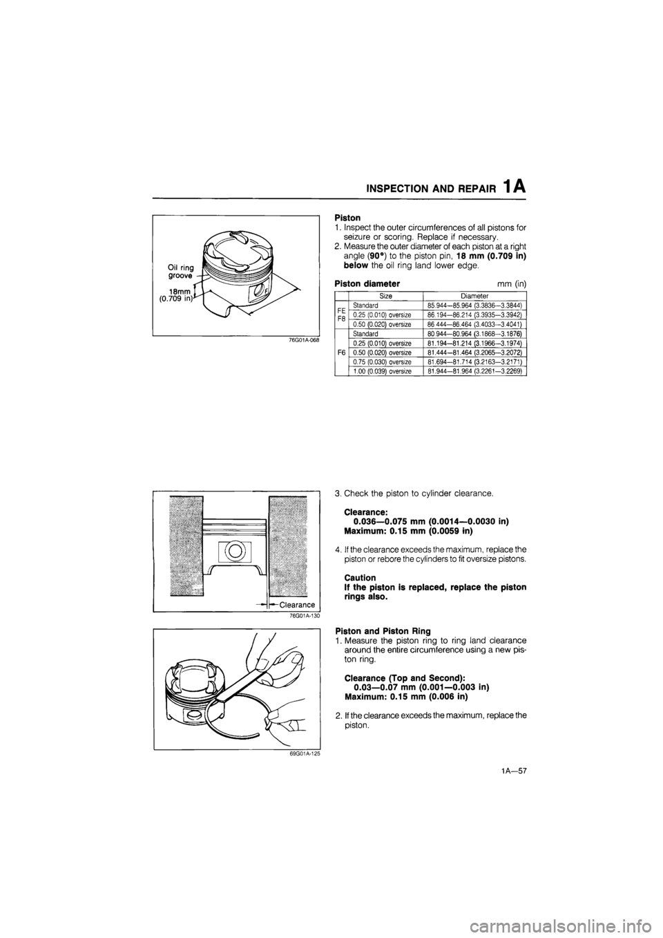
1. Inspect the outer circumferences of all pistons for
seizure or scoring. Replace if necessary.
2. Measure the outer diameter of each piston at a right
angle (90°) to the piston pin, 18 mm (0.709 in)
below the oil ring land lower edge.
Piston diameter mm (in)
Size Diameter
LU
OO LL LL Standard 85.944-85.964 (3.3836-3.3844)
LU
OO LL LL 0.25 (0.010) oversize 86.194-86.214 (3.3935-3.3942)
LU
OO LL LL
0.50 (0.020) oversize 86 444-86.464 (3.4033-3.4041)
F6
Standard 80 944-80.964 (3.1868-3.1876)
F6
0.25 (0.010) oversize 81.194-81.214 (3.1966-3.1974)
F6 0.50 (0.020) oversize 81.444-81.464 (3.2065-3.2072) F6
0.75 (0.030) oversize 81.694-81.714 (3.2163-3.2171)
F6
1.00 (0.039) oversize 81.944-81.964 (3.2261-3,2269)
3. Check the piston to cylinder clearance.
ClGdrsncG1
0.036—0.075 mm (0.0014—0.0030 in)
Maximum: 0.15 mm (0.0059 in)
4. If the clearance exceeds the maximum, replace the
piston or rebore the cylinders to fit oversize pistons.
Caution
If the piston is replaced, replace the piston
rings also.
76G01A-130
Piston and Piston Ring
1. Measure the piston ring to ring land clearance
around the entire circumference using a new pis-
ton ring.
Clearance (Top and Second):
0.03—0.07 mm (0.001—0.003 in)
Maximum: 0.15 mm (0.006 in)
2. If the clearance exceeds the maximum, replace the
piston.
69G01A-125
1A—57
Page 91 of 1865
INSPECTION AND REPAIR 1 A
76G01A-070
76G01A-071
86U01X-109
Connecting Rod
1. Measure the connecting rod small end bore.
Diameter: 21.943—21.961 mm (0.8640—0.8646 in)
2. Check the interference between the small end bore
and piston pin.
Interference:
0.013—0.037 mm (0.0005—0.0015 in)
3. Check each connecting rod for bending or twist-
ing. Repair or replace if necessary.
Bend: 0.06 mm (0.0024 in) max.
Twist: 0.06 mm (0.0024 in) max.
Crankshaft
1. Check the journals and pins for damage, scoring,
or oil hole clogging.
2. Set the crankshaft on V-blocks.
3. Check the crankshaft runout at the center journal.
Replace if necessary.
Runout: 0.03 mm (0.0012 in) max.
4. Measure each journal diameter in X and Y direc-
tions at two points.
Main journal
Diameter:
59.937—59.955 mm (2.3597—2.3604 in)
Out-of-round: 0.05 mm (0.0020 in) max.
Crankpin journal
Diameter:
50.940—50.955 mm (2.0055—2.0061 in)
Out-of-round: 0.05 mm (0.0020 in) max.
76G01A-131
1A—59