1987 MAZDA 626 brake
[x] Cancel search: brakePage 22 of 1865
0
1
o
interval
Procedure & Item
Number of Months or km, whichever corns first
©1 ©2 ©3 ©4 Service data and inspection point Page
interval
Procedure & Item
Months — 6 12 18 24 30 36 42 48 ©1 ©2 ©3 ©4 Service data and inspection point Page
interval
Procedure & Item
x
1000 Km
1 10 20 30 40 50 60 70 80 ©1 ©2 ©3 ©4 Service data and inspection point Page
interval
Procedure & Item
Miles x 1000
0.6 6 12 18 24 30 36 42 48
©1 ©2 ©3 ©4 Service data and inspection point Page
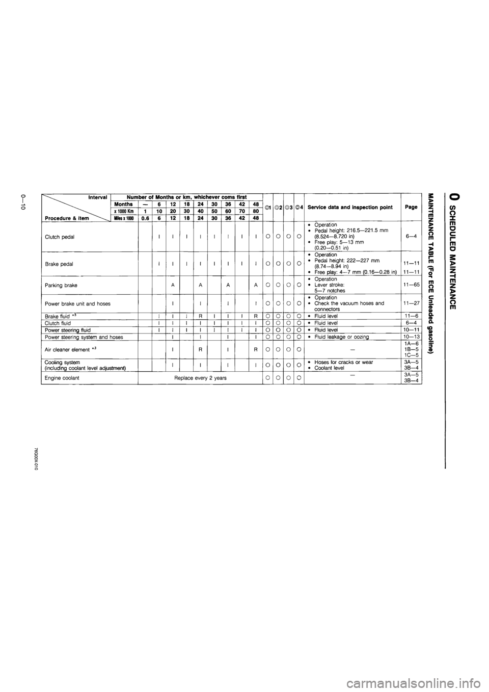
Clutch pedal I I I I I I I I O o o o
• Operation
• Pedal height: 216.5—221.5 mm (8.524—8.720 in)
• Free play: 5—13 mm (0.20—0.51 in)
6-4
Brake pedal I I I I I I I I O o o o
• Operation • Pedal height: 222—227 mm (8.74—8.94 in)
• Free play: 4—7 mm (0.16—0.28 in)
11-11
11—11
Parking brake A A A A o o o o
• Operation • Lever stroke: 5—7 notches
11-65
Power brake unit and hoses I I I I o o o o
• Operation • Check the vacuum hoses and connectors
11—27
Brake fluid *5 I I I R I I I R 0 o o o • Fluid level 11—6
Clutch fluid I I I I I I I I o o o 0 • Fluid level 6-4
Power steering fluid I I I I I I I I o o o o • Fluid level 10—11
Power steering system and hoses I I I I 0 o o 0 • Fluid leakage or oozing 10—13
Air cleaner element *3 I R I R o o o o —
1 A—6 1B—5 1C-5
Cooling system (including coolant level adjustment) I I I I o o o o • Hoses for cracks or wear • Coolant level
3A—5
3B-4
Engine coolant Replace every 2 years 0 o 0 0 — 3A-5 3B—4
a> a o o X o o
Page 25 of 1865
GO
Interval
Procedure & item
Number of Months or km, whichever corns first
©1 ©2 ©3 ©4 Service data and inspection point Page
Interval
Procedure & item
Months — 6 12 18 24 30 36 42 48 ©1 ©2 ©3 ©4 Service data and inspection point Page
Interval
Procedure & item
x 1000 Km 1 10 20 30 40 50 60 70 80 ©1 ©2 ©3 ©4 Service data and inspection point Page
Interval
Procedure & item Miles x 1000 0.6 6 12 18 24 30 36 42 48
©1 ©2 ©3 ©4 Service data and inspection point Page
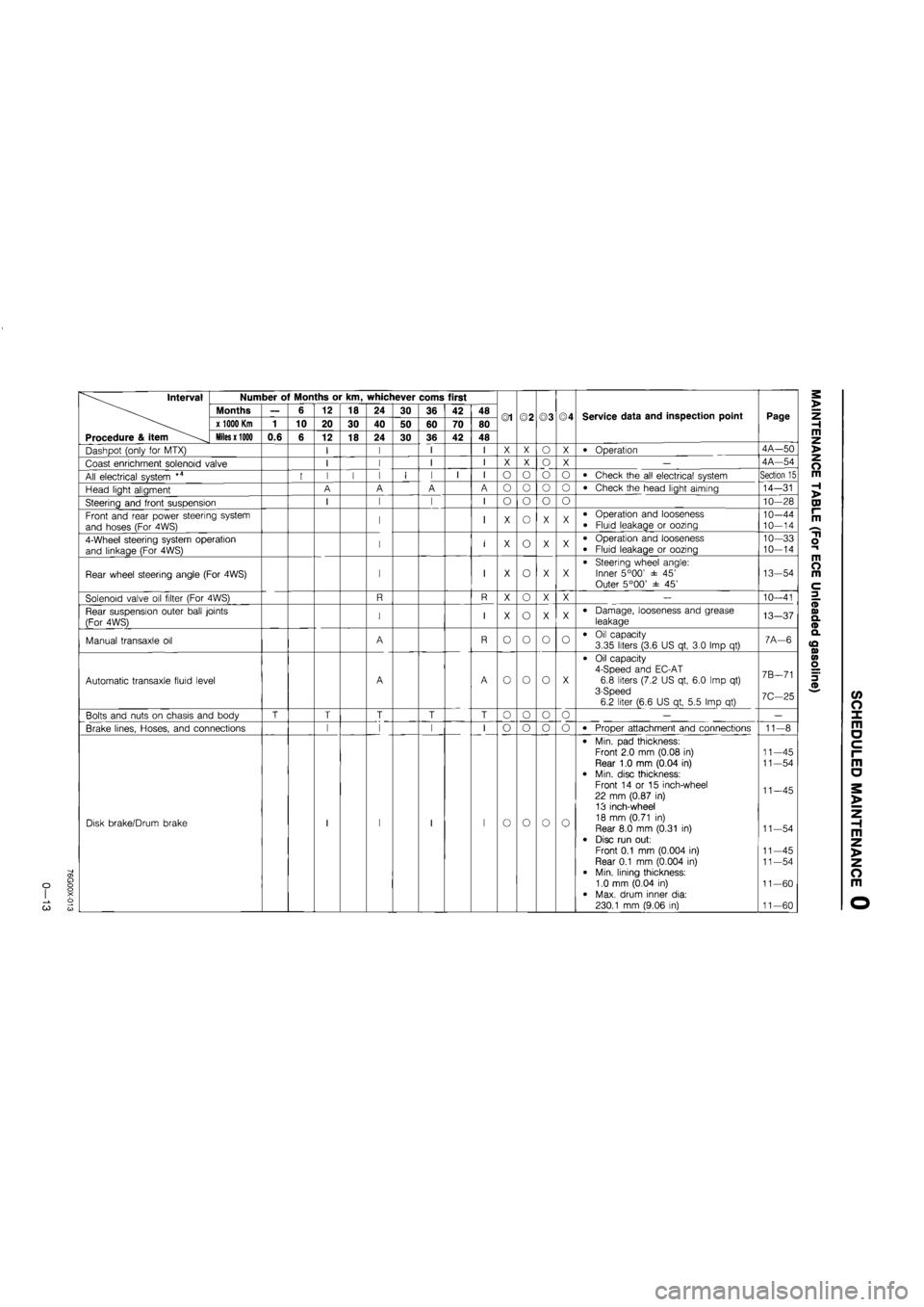
Dashpot (only for MTX) I I I I X X o X • Operation 4A—50
Coast enrichment solenoid valve I I I I X X o X — 4A—54
All electrical system *4 I I I I I I I I o o o o • Check the all electrical system Section 15
Head light aligment A A A A o o o o • Check the head light aiming 14-31
Steering and front suspension I I I I o o o o 10—28
Front and rear power steering system
and hoses (For 4WS) I I X o X X • Operation and looseness
• Fluid leakage or oozing 10—44
10-14
4-Wheel steering system operation
and linkage (For 4WS) I I X o X X • Operation and looseness
• Fluid leakage or oozing
10—33 10—14
Rear wheel steering angle (For 4WS) I I X o X X • Steering wheel angle: Inner 5°00' ± 45' Outer 5°00' ± 45'
13-54
Solenoid valve oil filter (For 4WS) R R X o X X — 10—41
Rear suspension outer ball joints
(For 4WS) I I X o X X • Damage, looseness and grease
leakage 13-37
Manual transaxle oil A R o o o o • Oil capacity 3.35 liters (3.6 US qt, 3.0 Imp qt) 7A—6
Automatic transaxle fluid level A A o o o X
• Oil capacity 4-Speed and EC-AT 6.8 liters (7.2 US qt, 6.0 Imp qt) 3-Speed 6.2 liter (6.6 US qt, 5.5 Imp qt)
7B—71
7C—25
Bolts and nuts on chasis and body T T T T T o o o o — —
Brake lines, Hoses, and connections I I I l_
I
o o o o • Proper attachment and connections 11-8
Disk brake/Drum brake I I I
l_
I o o o 0
• Min. pad thickness: Front 2.0 mm (0.08 in) Rear 1.0 mm (0.04 in)
• Min. disc thickness: Front 14 or 15 inch-wheel 22 mm (0.87 in)
13 inch-wheel 18 mm (0.71 in) Rear 8.0 mm (0.31 in)
• Disc run out:
Front 0.1 mm (0.004 in) Rear 0.1 mm (0.004 in) • Min. lining thickness: 1.0 mm (0.04 in)
• Max. drum inner dia: 230.1 mm (9.06 in)
11—45 11—54
11—45
11-54
11—45
11-54
11—60
11-60
Page 27 of 1865
For General
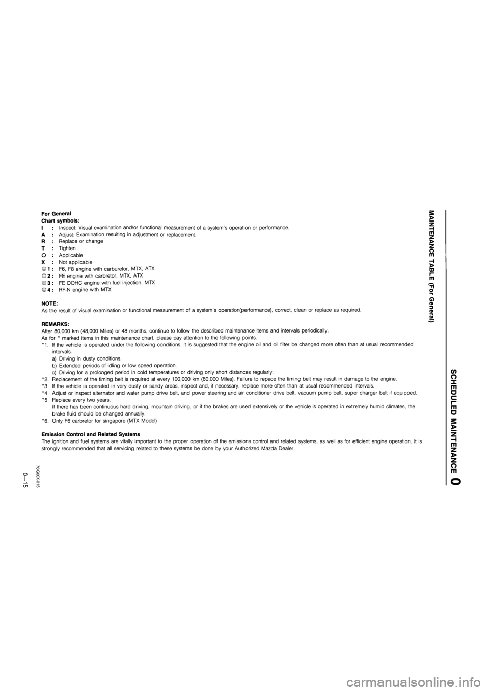
Chart symbols:
I : Inspect: Visual examination and/or functional measurement of a system's operation or performance.
A : Adjust: Examination resuiting in adjustment or replacement.
R : Replace or change
T : Tighten
O : Applicable
X : Not applicable
© 1 : F6, F8 engine with carburetor, MTX, ATX
© 2 : FE engine with carbretor, MTX, ATX
©3 : FE DOHC engine with fuel injection, MTX
® 4 : RF-N engine with MTX
NOTE:
As the result of visual examination or functional measurement of a system's operation(performance), correct, clean or replace as required.
REMARKS:
After 80,000 km (48,000 Miles) or 48 months, continue to follow the described maintenance items and intervals periodically.
As for * marked items in this maintenance chart, please pay attention to the following points.
*1. If the vehicle is operated under the following conditions, it is suggested that the engine oil and oil filter be changed more often than at usual recommended
intervals.
a) Driving in dusty conditions.
b) Extended periods of idling or low speed operation.
c) Driving for a prolonged period in cold temperatures or driving only short distances regularly.
"2. Replacement of the timing belt is required at every 100,000 km (60,000 Miles). Failure to repace the timing belt may result in damage to the engine.
*3 If the vehicle is operated in very dusty or sandy areas, inspect and, if necessary, replace more often than at usual recommended intervals.
*4 Adjust or inspect alternator and water pump drive belt, and power steering and air conditioner drive belt, vacuum pump belt, super charger belt if equipped.
*5 Replace every two years.
If there has been continuous hard driving, mountain driving, or if the brakes are used extensively or the vehicle is operated in extremely humid climates, the
brake fluid should be changed annually.
*6. Only F6 carbretor for Singapore (MTX Model)
Emission Control and Related Systems
The ignition and fuel systems are vitally important to the proper operation of the emissions control and related systems, as well as for efficient engine operation. It i
strongly recommended that all servicing related to these systems be done by your Authorized Mazda Dealer.
o CJ1
Page 28 of 1865
0 1
CO
interval Number of Months or km, whichever corns first
Months — 6 12 18 24 30 36 42 48 ©1 ©2 ©3 ©4 Service data and inspection point Page x 1000 Km 1 10 20 30 40 50 60 70 80 ©1 ©2 ©3 ©4 Service data and inspection point Page
Procedure & item Miles x 1000 0.6 6 12 18 24 30 36 42 48
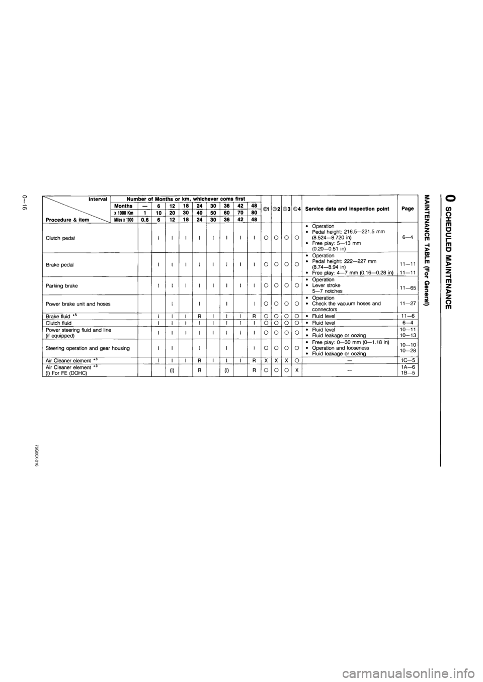
Clutch pedal I I I I I I I I O o o o
• Operation • Pedal height: 216.5—221.5 mm (8.524—8.720 in) • Free play: 5—13 mm (0.20—0.51 in)
6—4
Brake pedal I I I I I I I I o o o o
• Operation
• Pedal height: 222—227 mm (8.74—8.94 in)
• Free play: 4—7 mm (0.16—0.28 in)
11-11
11—11
Parking brake I I I I I I I I o o o o
• Operation • Lever stroke 5—7 notches 11-65
Power brake unit and hoses I I I I o o o o
• Operation • Check the vacuum hoses and connectors
11—27
Brake fluid *s I I I R I I I R o o o o • Fluid level 11-6
Clutch fluid I I I I I I I I o o o o • Fluid level 6-4
Power steering fluid and line (if equipped) I I I I I I I I o o o o • Fluid level • Fluid leakage or oozing
10—11
10—13
Steering operation and gear housing I I I I I o o o o
• Free play: 0—30 mm (0—1.18 in) • Operation and looseness • Fluid leakage or oozing
10—10
10-28
Air Cleaner element *3 I I I R I I I R X X X o — 1C—5
Air Cleaner element *3 (1) For FE (DOHC) (0 R (I) R o o o X — 1A—6
1B—5
Page 31 of 1865

CD
o> O o o X o
Interval
Procedure & item
Number of Months or km, whichever corns first
©1 ©2 ©3 ©4 Service data and inspection point Page
Interval
Procedure & item
Months — 6 12 18 24 30 36 42 48 ©1 ©2 ©3 ©4 Service data and inspection point Page
Interval
Procedure & item
x 1000 Km
1 10 20 30 40 50 60 70 80 ©1 ©2 ©3 ©4 Service data and inspection point Page
Interval
Procedure & item
Miles x 1000
0.6 6 12 18 24 30 36 42 48
©1 ©2 ©3 ©4 Service data and inspection point Page
Idle mixture (1) only for carbretor (I) I I I I O O o X
• CO concentration 2.0 ± 0.5 % CO concentration FE DOHC 1.5 ± 0.5 % HC concentration FE DOHC Less than 1000 rpm
4A-38
4C-30
Evaporative system
(only for middle east) I I I I X O X X — 4A—78
Dashpot (only for MTX) I I I I o X X X • Operation 4A—50
Coasting leaner system *6 t I I I
,
O X X X — 4A-56
Brake lines, hoses and connections I I I I o o o o • Proper attachment and connections 11-8
Disc brakes [ I I I I [ I I o o o o
• Min. pad thickness: Front 2.0 mm (0.08 in) Rear 1.0 mm (0.04 in)
• Min. disc thickness: Front 14 or 15 inch-wheel 22 mm (0.87 in)
13 inch-whel 18 mm (0.71 in) Rear 8.0 mm (0.31 in) • Disc run out: Front 0.1 mm (0.004 in) Rear 0.1 mm (0.004 in)
11—45 11—54
11—45
11—54
11—45
11—54
Drum brakes I I I I o o X o
• Min. lining thickness: 1.0 mm (0.004 in)
• Max. drum inner dia: 14 or 15 inch-wheel 230.1 mm (9.06 in) 13 inch-wheel 201.5 mm (7.93 in)
11-60
11—60
Steering linkages, rack guide and tie
rod ends I I I I I o o o o • Operation and looseness 10-11
Manual transaxle oil R o o 0 o • Oil capacity
3.35 liters (3.6 US qt, 3.0 Imp qt) 7A—6
Automatic transaxle fluid level I I I I o o X X
• Oil capacity 4-Speed 6.8 liters (7.2 US qt, 6.0 Imp qt) 3-Speed 6.2 liters (6.6 US qt, 5.5 Imp qt)
7B—71
7C-25
m z >
o m
H >
CO I-m
"ti o
a
Page 37 of 1865

TROUBLESHOOTING GUIDE 1 A
Problem Possible Cause Remedy Page
Insufficient power Insufficient compression Malfunction of HLA Improper valve clearance Compression leakage from valve seat Seized valve stem Weak or broken valve spring Failed cylinder head gasket Cracked or distorted cylinder head Sticking, damaged, or worn piston ring Cracked or worn piston
Replace
Adjust
Repair
Replace Replace Replace Replace Replace Replace
1A—75 1A—10
1
A—51 1A—49 1A—53
1
A—20 1A—48 1A—57
1
A—57
Malfunction of fuel system Refer to Section 4
Others Slipping clutch Dragging brakes Wrong size tires
Refer to Section 6 Refer to Section 11 Refer to Section 12
Abnormal
combustion
Malfunction of engine-related components Malfunction of HLA
Improper valve clearance Sticking or burned valve
Weak or broken valve spring Carbon accumulation in combustion chamber
Replace Adjust Replace Replace
Eliminate carbon
1
A—75 1A—10 1A—49 1A—53
Malfunction of fuel system Refer to Section 4
Engine noise Crankshaft or bearing related parts
Excessive main bearing oil clearance Main bearing seized or heat-damaged Excessive crankshaft end play Excessive connecting rod bearing oil clearance Connecting rod bearing seized or heat-damaged
Replace or repair Replace
Replace or repair Replace or repair Replace
1A—65
1
A—65 1A—66 1A—67
1
A—67
Piston related parts Worn cylinder Worn piston or piston pin Seized piston Damaged piston ring Bent connecting rod
Replace or repair
Replace
Replace Replace Replace
1A—55
1
A—57
1
A—57
1
A—57 1A—59
Valves or timing related parts Malfunction of HLA* Improper valve clearance Broken valve spring Excessive valve guide clearance Malfunction of timing belt tensioner
Replace Adjust
Replace Replace Replace
1A—75 1A—10 1A—53 1A—49 1A—61
Malfunction of cooling system Refer to Section 3A
Malfunction of fuel system Refer to Section 4
Others Malfunction of water pump bearing Improper drive belt tension Malfunction of alternator bearing Exhaust gas leakage
Replace Adjust Replace Repair
1 A— 7
1
A—48
* Tappet noise may occur if the engine is not operated for an extended period of time. The noise should stop after the
engine has reached normal operating temperature.
76G01A-005
1A—5
Page 53 of 1865
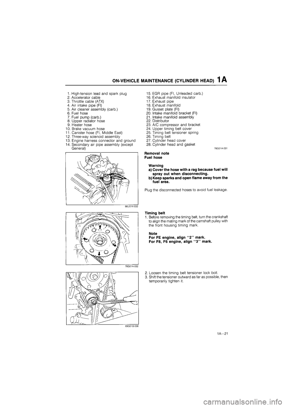
1 A ON-VEHICLE MAINTENANCE (CYLINDER HEAD)
1. High-tension lead and spark plug
2. Accelerator cable
3. Throttle cable (ATX)
4. Air intake pipe (Fl)
5. Air cleaner assembly (carb.)
6. Fuel hose
7. Fuel pump (carb.)
8. Upper radiator hose
9. Heater hose
10. Brake vacuum hose
11. Canister hose (Fl, Middle East)
12. Three-way solenoid assembly
13. Engine harness connector and ground
14. Secondary air pipe assembly (except
General)
15. EGR pipe (Fl, Unleaded carb.)
16. Exhaust manifold insulator
17. Exhaust pipe
18. Exhaust manifold
19. Gusset plate (Fl)
20. Intake manifold bracket (Fl)
21. Intake manifold assembly
22. Distributor
23. A/C compressor and bracket
24. Upper timing belt cover
25. Timing belt tensioner spring
26. Timing belt
27. Cylinder head cover
28. Cylinder head and gasket 76G01A-031
Removal note
Fuel hose
Warning
a) Cover the hose with a rag because fuel will
spray out when disconnecting.
b) Keep sparks and open flame away from the
fuel area.
Plug the disconnected hoses to avoid fuel leakage.
Timing belt
1. Before removing the timing belt, turn the crankshaft
to align the mating mark of the camshaft pulley with
the front housing timing mark.
Note
For FE engine, align "2" mark.
For F8, F6 engine, align "3" mark.
2. Loosen the timing belt tensioner lock bolt.
3. Shift the tensioner outward as far as possible, then
temporarily tighten it.
1A—21
Page 67 of 1865
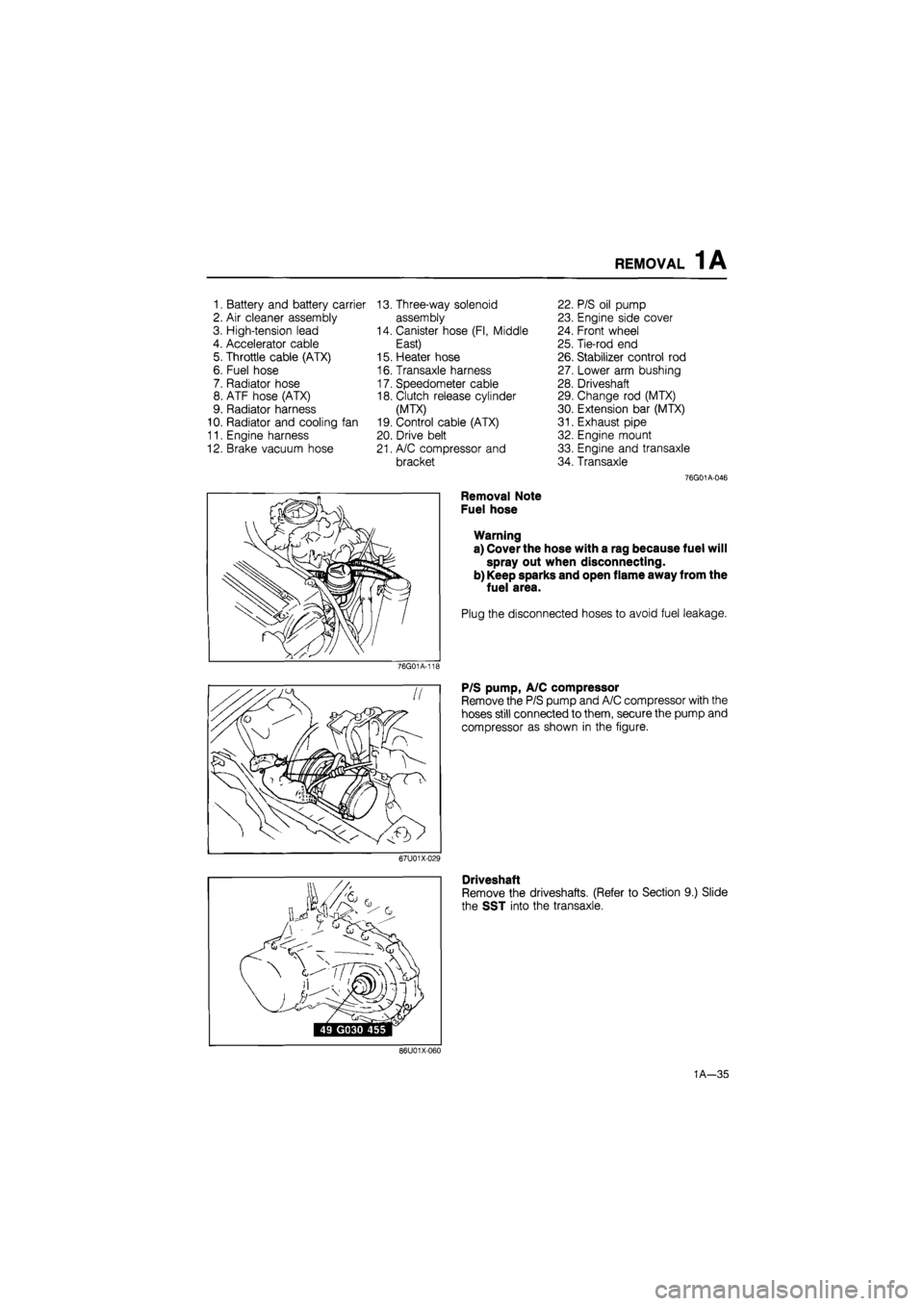
REMOVAL 1A
1. Battery and battery carrier 13. Three-way solenoid 22. P/S oil pump
2. Air cleaner assembly assembly 23. Engine side cover
3. High-tension lead 14. Canister hose (Fl, Middle 24. Front wheel
4. Accelerator cable East) 25. Tie-rod end
5. Throttle cable (ATX) 15. Heater hose 26. Stabilizer control rod
6. Fuel hose 16. Transaxle harness 27. Lower arm bushing
7. Radiator hose 17. Speedometer cable 28. Driveshaft
8. ATF hose (ATX) 18. Clutch release cylinder 29. Change rod (MTX)
9. Radiator harness (MTX) 30. Extension bar (MTX)
10. Radiator and cooling fan 19. Control cable (ATX) 31. Exhaust pipe
11. Engine harness 20. Drive belt 32. Engine mount
12. Brake vacuum hose 21. A/C compressor and 33. Engine and transaxle
bracket 34. Transaxle
76G01A-046
Removal Note
Fuel hose
Warning
a) Cover the hose with a rag because fuel will
spray out when disconnecting.
b) Keep sparks and open flame away from the
fuel area.
Plug the disconnected hoses to avoid fuel leakage.
76G01A-11E
P/S pump, A/C compressor
Remove the P/S pump and A/C compressor with the
hoses still connected to them, secure the pump and
compressor as shown in the figure.
67U01X-029
Driveshaft
Remove the driveshafts. (Refer to Section 9.) Slide
the SST into the transaxle.
86U01X-060
1A—35