Page 298 of 878
TURBO PRESSURE SENSOR
COMPONENTS FOR REMOVAL AND
INSTALLATION
TURBO PRESSURE SENSOR
INSPECTION
1. INSPECT POWER SOURCE VOLTAGE OF TURBO
PRESSURE SENSOR
(a) Disconnect the turbo pressure sensor connector.
(b) Turn the ignition switch ON.
(c) Using a voltmeter, measure the voltage between connector
terminals VC and E2 of the wiring harness side.
Voltage:
4.5±5.5 V
(d) Turn the ignition switch OFF.
(e) Reconnect the turbo pressure sensor connector. EG±314
± ENGINESFI SYSTEM (2JZ±GTE)
Page 299 of 878
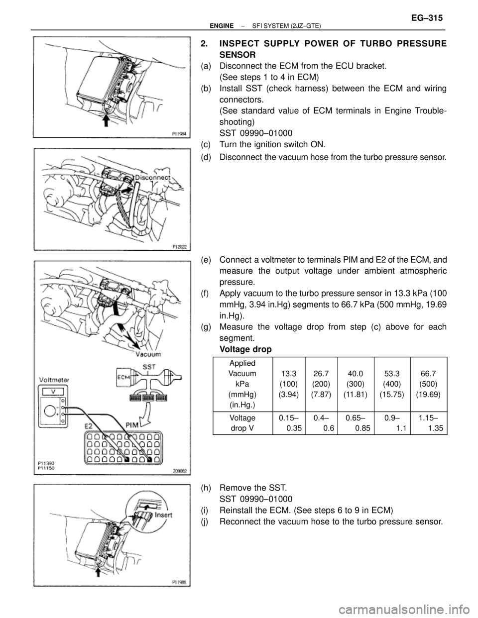
2. INSPECT SUPPLY POWER OF TURBO PRESSURE
SENSOR
(a) Disconnect the ECM from the ECU bracket.
(See steps 1 to 4 in ECM)
(b) Install SST (check harness) between the ECM and wiring
connectors.
(See standard value of ECM terminals in Engine Trouble-
shooting)
SST 09990±01000
(c) Turn the ignition switch ON.
(d) Disconnect the vacuum hose from the turbo pressure sensor.
(e) Connect a voltmeter to terminals PIM and E2 of the ECM, and
measure the output voltage under ambient atmospheric
pressure.
(f) Apply vacuum to the turbo pressure sensor in 13.3 kPa (100
mmHg, 3.94 in.Hg) segments to 66.7 kPa (500 mmHg, 19.69
in.Hg).
(g) Measure the voltage drop from step (c) above for each
segment.
Voltage drop
������ �
����� �
����� �
����� �
����� ������
Applied
Vacuum
kPa
(mmHg)
(in.Hg.)���� �
��� �
��� �
��� �
��� ����
13.3
(100)
(3.94)
���� �
��� �
��� �
��� �
��� ����
26.7
(200)
(7.87)
���� �
��� �
��� �
��� �
��� ����
40.0
(300)
(11.81)
���� �
��� �
��� �
��� �
��� ����
53.3
(400)
(15.75)
���� �
��� �
��� �
��� �
��� ����
66.7
(500)
(19.69)
������ �
����� ������
Voltage
drop V���� �
��� ����
0.15±
0.35���� �
��� ����
0.4±
0.6���� �
��� ����
0.65±
0.85���� �
��� ����
0.9±
1.1���� �
��� ����
1.15±
1.35
(h) Remove the SST.
SST 09990±01000
(i) Reinstall the ECM. (See steps 6 to 9 in ECM)
(j) Reconnect the vacuum hose to the turbo pressure sensor.
± ENGINESFI SYSTEM (2JZ±GTE)EG±315
Page 313 of 878
09205±76030Cylinder Head Setting Bolt
Tightening Adaptor
09268±41045Injection Measuring Tool Set
(09268±41070)No.4 Union
(09268±41090)No.7 Union
(90405±09015)No.1 Union
09268±45012 EFI Fuel Pressure Gauge
ECT sensor
09612±24014 Steering Gear Housing Overhaul
Tool Set
(09617±24011) Steering Rack Wrench
09631±22020 Power Steering Hose Nut
14 x 17 mm Wrench Set
09808±14010Fuel Sender Gauge Tool Assy
09816±30010 Oil Pressure Switch Socket
09842±30070 Wiring ªFº EFI InspectionInjector
Knock sensor
Fuel line flare nut
Fuel pressure pulsation damper
SFI SYSTEM (2JZ±GE)
PREPARATION
SST (SPECIAL SERVICE TOOLS)
± ENGINESFI SYSTEM (2JZ±GE)EG±187
Page 316 of 878
IF VEHICLE IS EQUIPPED WITH MOBIL
RADIO SYSTEM (HAM, CB, ETC.)
If the vehicle is equipped with a mobile communication sys-
tem, refer to the precaution in the IN section.
AIR INDUCTION SYSTEM
1. Separation of the engine oil dipstick, oil filler cap, PCV hose,
etc. may cause the engine to run out of tune.
2. Disconnection, looseness or cracks in the parts of the air
induction system between the throttle body and cylinder
head will cause air suction and cause the engine to run out
of tune.
ELECTRONIC CONTROL SYSTEM
1. Before removing SFI wiring connectors, terminals, etc., first
disconnect the power by either turning the ignition switch
OFF or disconnecting the negative (±) terminal cable from the
battery.
HINT: Always check the diagnostic trouble code before dis-
connecting the negative (±) terminal cable from the battery.
2. When installing the battery, be especially careful not to
incorrectly connect the positive (+) and negative (±) cables.
3. Do not permit parts to receive a severe impact during removal
or installation. Handle all SFI parts carefully, especially the
ECM.
4. Do not be careless during troubleshooting as there are
numerous transistor circuits and even slight terminal contact
can cause further troubles.
5. Do not open the ECM cover.
6. When inspecting during rainy weather, take care to prevent
entry of water. Also, when washing the engine compartment,
prevent water from getting on the SFI parts and wiring
connectors.
7. Parts should be replaced as an assembly.
8. Care is required when pulling out and inserting wiring
connectors.
(a) Release the lock and pull out the connector, pulling on the
connectors.
(b) Fully insert the connector and check that it is locked. EG±190
± ENGINESFI SYSTEMS (2JZ±GE)
Page 317 of 878
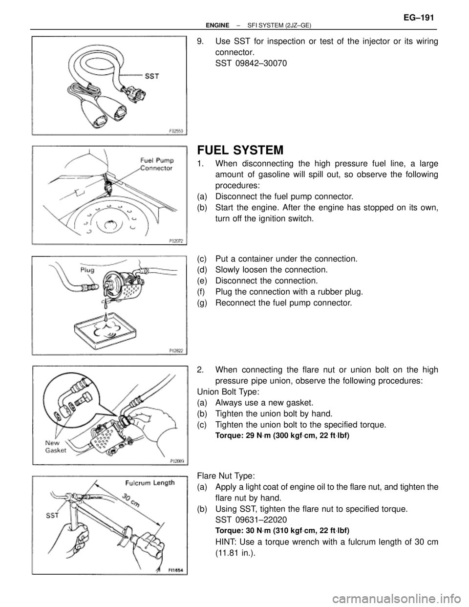
9. Use SST for inspection or test of the injector or its wiring
connector.
SST 09842±30070
FUEL SYSTEM
1. When disconnecting the high pressure fuel line, a large
amount of gasoline will spill out, so observe the following
procedures:
(a) Disconnect the fuel pump connector.
(b) Start the engine. After the engine has stopped on its own,
turn off the ignition switch.
(c) Put a container under the connection.
(d) Slowly loosen the connection.
(e) Disconnect the connection.
(f) Plug the connection with a rubber plug.
(g) Reconnect the fuel pump connector.
2. When connecting the flare nut or union bolt on the high
pressure pipe union, observe the following procedures:
Union Bolt Type:
(a) Always use a new gasket.
(b) Tighten the union bolt by hand.
(c) Tighten the union bolt to the specified torque.
Torque: 29 NVm (300 kgfVcm, 22 ftVlbf)
Flare Nut Type:
(a) Apply a light coat of engine oil to the flare nut, and tighten the
flare nut by hand.
(b) Using SST, tighten the flare nut to specified torque.
SST 09631±22020
Torque: 30 NVm (310 kgfVcm, 22 ftVlbf)
HINT: Use a torque wrench with a fulcrum length of 30 cm
(11.81 in.).
± ENGINESFI SYSTEM (2JZ±GE)EG±191
Page 319 of 878
FUEL PUMP
ON±VEHICLE INSPECTION
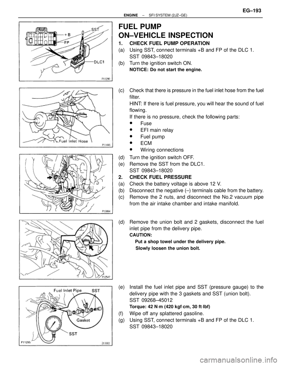
1. CHECK FUEL PUMP OPERATION
(a) Using SST, connect terminals +B and FP of the DLC 1.
SST 09843±18020
(b) Turn the ignition switch ON.
NOTICE: Do not start the engine.
(c) Check that there is pressure in the fuel inlet hose from the fuel
filter.
HINT: If there is fuel pressure, you will hear the sound of fuel
flowing.
If there is no pressure, check the following parts:
wFuse
wEFI main relay
wFuel pump
wECM
wWiring connections
(d) Turn the ignition switch OFF.
(e) Remove the SST from the DLC1.
SST 09843±18020
2. CHECK FUEL PRESSURE
(a) Check the battery voltage is above 12 V.
(b) Disconnect the negative (±) terminals cable from the battery.
(c) Remove the 2 nuts, and disconnect the No.2 vacuum pipe
from the air intake chamber and intake manifold.
(d) Remove the union bolt and 2 gaskets, disconnect the fuel
inlet pipe from the delivery pipe.
CAUTION:
� Put a shop towel under the delivery pipe.
� Slowly loosen the union bolt.
(e) Install the fuel inlet pipe and SST (pressure gauge) to the
delivery pipe with the 3 gaskets and SST (union bolt).
SST 09268±45012
Torque: 42 NVm (420 kgfVcm, 30 ftVlbf)
(f) Wipe off any splattered gasoline.
(g) Using SST, connect terminals +B and FP of the DLC 1.
SST 09843±18020
± ENGINESFI SYSTEM (2JZ±GE)EG±193
Page 330 of 878
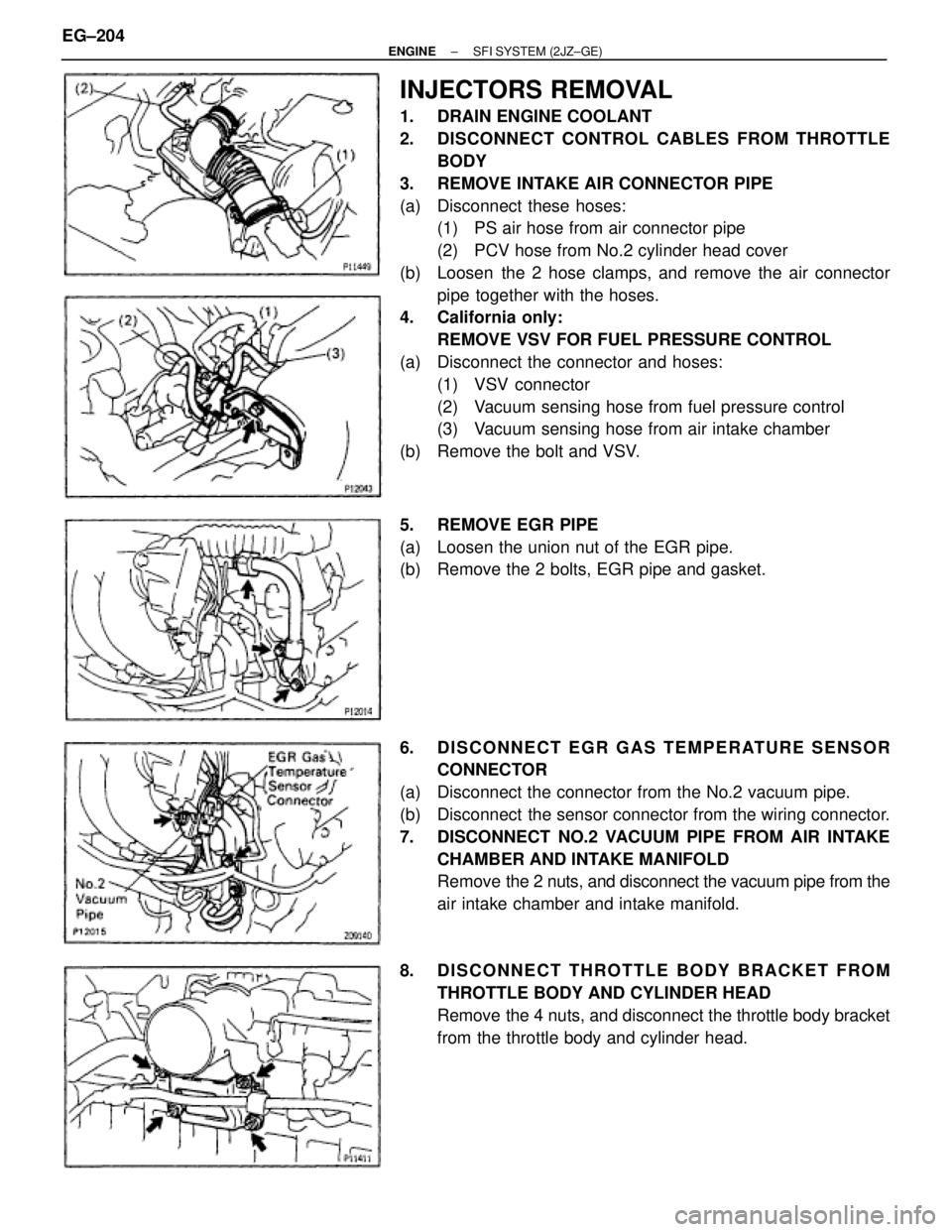
INJECTORS REMOVAL
1. DRAIN ENGINE COOLANT
2. DISCONNECT CONTROL CABLES FROM THROTTLE
BODY
3. REMOVE INTAKE AIR CONNECTOR PIPE
(a) Disconnect these hoses:
(1) PS air hose from air connector pipe
(2) PCV hose from No.2 cylinder head cover
(b) Loosen the 2 hose clamps, and remove the air connector
pipe together with the hoses.
4. California only:
REMOVE VSV FOR FUEL PRESSURE CONTROL
(a) Disconnect the connector and hoses:
(1) VSV connector
(2) Vacuum sensing hose from fuel pressure control
(3) Vacuum sensing hose from air intake chamber
(b) Remove the bolt and VSV.
5. REMOVE EGR PIPE
(a) Loosen the union nut of the EGR pipe.
(b) Remove the 2 bolts, EGR pipe and gasket.
6. DISCONNECT EGR GAS TEMPERATURE SENSOR
CONNECTOR
(a) Disconnect the connector from the No.2 vacuum pipe.
(b) Disconnect the sensor connector from the wiring connector.
7. DISCONNECT NO.2 VACUUM PIPE FROM AIR INTAKE
CHAMBER AND INTAKE MANIFOLD
Remove the 2 nuts, and disconnect the vacuum pipe from the
air intake chamber and intake manifold.
8. DISCONNECT THROTTLE BODY BRACKET FROM
THROTTLE BODY AND CYLINDER HEAD
Remove the 4 nuts, and disconnect the throttle body bracket
from the throttle body and cylinder head. EG±204
± ENGINESFI SYSTEM (2JZ±GE)
Page 351 of 878
IDLE AIR CONTROL (IAC) VALVE
ON±VEHICLE INSPECTION
1. INSPECT IAC VALVE FOR OPERATING SOUND
Check that there is a clicking sound immediately after stop-
ping the engine.
If operation is not as specified, check the IAC valve, wiring
and ECM.
2. California only:
INSPECT AIR ASSIST SYSTEM
A. Warm up engine
Allow the engine to warm up to normal operating tempera-
ture.
B. Check idle speed
Idle speed (Transmission in neutral position):
700 + 50 rpm
C. Check IAC valve operation
With engine idling, pinch the air hose and check that engine
speed drops, and then returns back up to idle speed.
If operation is not as specified, check the IAC valve, wiring
and ECM.
3. INSPECT IAC VALVE RESISTANCE
Using an ohmmeter, measure the resistance between the ter-
minals (B1 (or B2) to others).
Resistance:
At 20°C (68°F) 18±22 �
If the resistance is not as specified, replace the IAC valve.
± ENGINESFI SYSTEM (2JZ±GE)EG±225


