Page 609 of 878
* The system shown here is an EXAMPLE ONLY. It is different to the actual circuit shown in the SYSTEM CIRCUITS SECTION.
POWER SOURCE (Current Flow Chart)
The chart below shows the route by which current flows from the battery to each electrical source (Fusible Link, Circuit
Breaker, Fuse, etc.) and other parts.
The next page and following pages show the parts to which each electrical source outputs current.
POWER SOURCE
8
HOW TO USE THIS MANUAL
The ªCurrent Flow Chartº section, describes which parts each power source (fuses, fusible links, and circuit breakers)
transmits current to. In the Power Source circuit diagram, the conditions when battery power is supplied to each system are
explained. Since all System Circuit diagrams start from the power source, the power source system must be fully understood.
Page 610 of 878
* The system shown here is an EXAMPLE ONLY. It is different to the actual circuit shown in the SYSTEM CIRCUITS SECTION.
GROUND POINTS
9
The ground points circuit diagram shows the connections from all major parts to the respective ground points. When
troubleshooting a faulty ground point, checking the system circuits which use a common ground may help you identify the
problem ground quickly. The relationship between ground points ( , , and shown below) can also be
checked this way.
Page 619 of 878
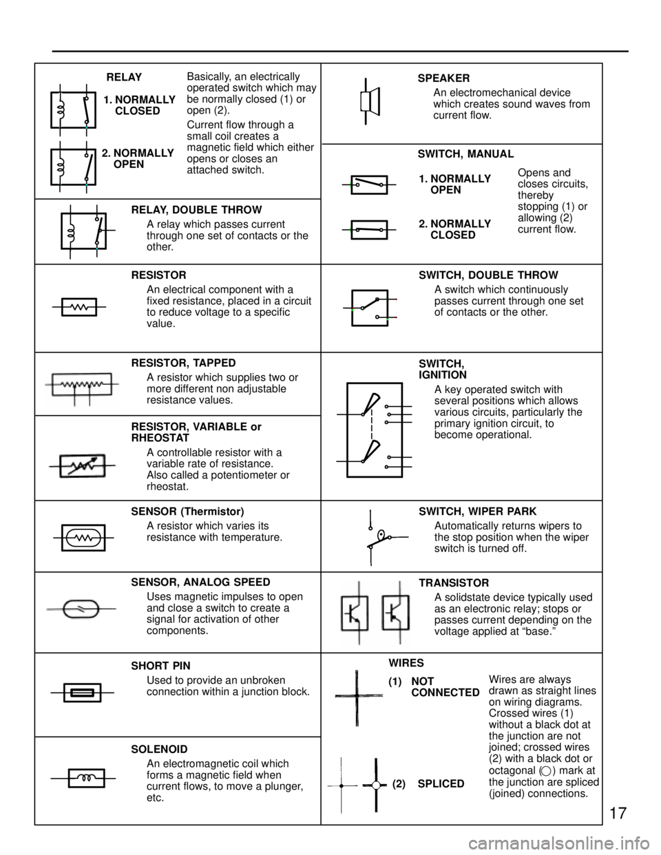
17
1. NORMALLY
OPENOpens and
closes circuits,
thereby
stopping (1) or
allowing (2)
current flow.
RESISTOR
An electrical component with a
fixed resistance, placed in a circuit
to reduce voltage to a specific
value.
RESISTOR, TAPPED
A resistor which supplies two or
more different non adjustable
resistance values.
SENSOR (Thermistor)
A resistor which varies its
resistance with temperature.
SHORT PIN
Used to provide an unbroken
connection within a junction block.
SOLENOID
An electromagnetic coil which
forms a magnetic field when
current flows, to move a plunger,
etc.SWITCH, DOUBLE THROW
A switch which continuously
passes current through one set
of contacts or the other.
SWITCH,
IGNITION
A key operated switch with
several positions which allows
various circuits, particularly the
primary ignition circuit, to
become operational.
Wires are always
drawn as straight lines
on wiring diagrams.
Crossed wires (1)
without a black dot at
the junction are not
joined; crossed wires
(2) with a black dot or
octagonal (
) mark at
the junction are spliced
(joined) connections. RELAY, DOUBLE THROW
A relay which passes current
through one set of contacts or the
other.
SENSOR, ANALOG SPEED
Uses magnetic impulses to open
and close a switch to create a
signal for activation of other
components.TRANSISTOR
A solidstate device typically used
as an electronic relay; stops or
passes current depending on the
voltage applied at ªbase.º SWITCH, WIPER PARK
Automatically returns wipers to
the stop position when the wiper
switch is turned off. SWITCH, MANUAL SPEAKER
An electromechanical device
which creates sound waves from
current flow.
2. NORMALLY
CLOSED
RESISTOR, VARIABLE or
RHEOSTAT
A controllable resistor with a
variable rate of resistance.
Also called a potentiometer or
rheostat. 2. NORMALLY
OPEN RELAY
1. NORMALLY
CLOSEDBasically, an electrically
operated switch which may
be normally closed (1) or
open (2).
Current flow through a
small coil creates a
magnetic field which either
opens or closes an
attached switch.
(2) SPLICED WIRES
(1) NOT
CONNECTED
Page 841 of 878
246
HOW TO USE THIS MANUAL
OVERALL ELECTRICAL WIRING DIAGRAM
Page 842 of 878
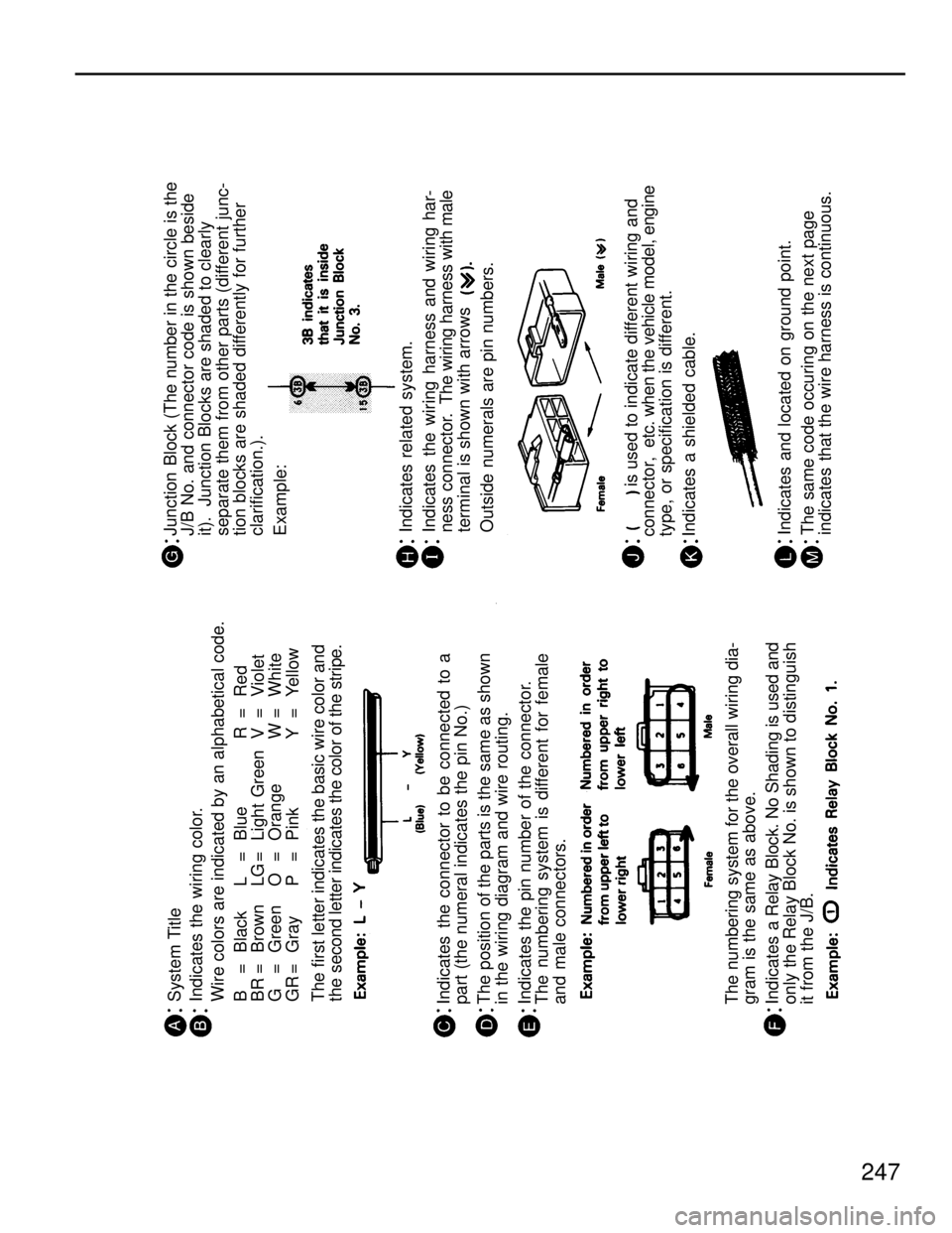
Junction Block (The number in the circle is the
J/B No. and connector code is shown beside
it). Junction Blocks are shaded to clearly
separate them from other parts (different junc-
tion blocks are shaded differently for further
clarification.).
Example:
Indicates related system.
Indicates the wiring harness and wiring har-
ness connector. The wiring harness with male
terminal is shown with arrows
Outside numerals are pin numbers.
is used to indicate different wiring and
connector, etc. when the vehicle model, engine
type, or specification is different.
Indicates a shielded cable.
Indicates and located on ground point.
The same code occuring on the next page
indicates that the wire harness is continuous. System Title
Indicates the wiring color.
Wire colors are indicated by an alphabetical code.
B = Black L = Blue R = Red
BR = Brown LG = Light Green V = Violet
G = Green O = Orange W = White
GR = Gray P = Pink Y = Yellow
The first letter indicates the basic wire color and
the second letter indicates the color of the stripe.
Indicates the connector to be connected to a
part (the numeral indicates the pin No.)
The position of the parts is the same as shown
in the wiring diagram and wire routing.
Indicates the pin number of the connector.
The numbering system is different for female
and male connectors.
The numbering system for the overall wiring dia-
gram is the same as above.
Indicates a Relay Block. No Shading is used and
only the Relay Block No. is shown to distinguish
it from the J/B.
247
Page 843 of 878
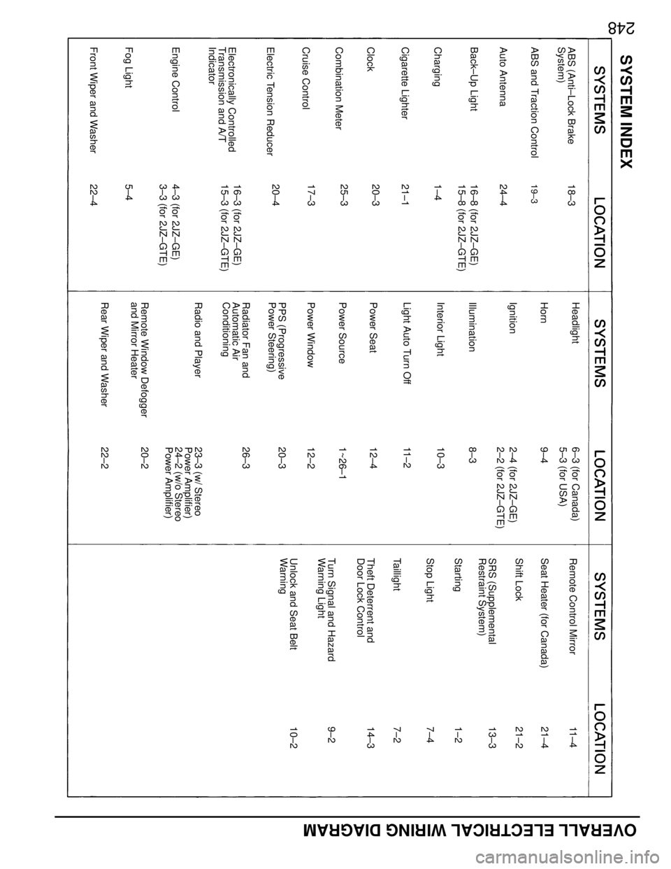
Remote Control MirrorSeat Heater (for Canada)SRS (Supplemental
Restraint System)Shift LockStartingTheft Deterrent and
Door Lock ControlTurn Signal and Hazard
Warning LightUnlock and Seat Belt
Warning
HeadlightHornIlluminationInterior LightLight Auto Turn OffPower SeatPower SourcePower WindowPPS (Progressive
Power Steering)Radio and Player
ABS (Anti±Lock Brake
System)Auto AntennaABS and Traction ControlBack±Up LightChargingCigarette LighterCombination MeterCruise ControlElectronically Controlled
Transmission and A/T
IndicatorEngine ControlFog Light
5±417±325±321±11±416±8 (for 2JZ±GE)24±418±319±3
23±3 (w/ Stereo
Power Amplifier)
24±2 (w/o Stereo
Power Amplifier)1~26±120±312±212±411±28±310±3
13±321±29±214±31±27±4
Taillight
11±421±47±210±2
SYSTEM INDEX
Stop Light
248
Clock
20±315±8 (for 2JZ±GTE)
Electric Tension Reducer
20±416±3 (for 2JZ±GE)15±3 (for 2JZ±GTE)
Front Wiper and Washer
22±44±3 (for 2JZ±GE)3±3 (for 2JZ±GTE)
6±3 (for Canada)5±3 (for USA)
Ignition
9±42±4 (for 2JZ±GE)2±2 (for 2JZ±GTE)
Radiator Fan and
Automatic Air
Conditioning
26±3
Remote Window Defogger
and Mirror Heater
20±2
Rear Wiper and Washer
22±2
OVERALL ELECTRICAL WIRING DIAGRAM
Page 845 of 878
OVERALL ELECTRICAL WIRING DIAGRAM
1
234
2SUPRA
2IG2AM2 3
IJ11IJ19
4IB1
2
2A2 1
2 1
2 1
2 1
2 1
2 1
2A 6B 5B 4B 10B 11B 12B
1A 1B 2B 3B 9B 8B 4A3A 7B2 1
2 1
ECEC +B IGC1 IGC2 IGC3 IGC4 IGC5 IGC6
TACH IGT1 IGT2 IGT3 IGT4 IGT5 IGT6 IGF+B
IGTEXT
IGFC±
N E G1 G2 G± IGNITER
I6
IGNITION COIL NO. 1 I7
IGNITION COIL NO. 2 I8
IGNITION COIL NO. 3 I9
IGNITION COIL NO. 4 I10
IGNITION COIL NO. 5 I11
IGNITION COIL NO. 6
IGNITER
D4
DI STRI B UT OR
N1
NOI S E
FIL TER
To Dat a Link Connector 1
(
Chec k Connector)
< 3±3>
To Engine Contr ol Module
(
Engine and Electronically
Controlled Transmission ECU)
<3±5>I5
IGNITION
COIL
N1
NOISE
FILTER
To Engine Contr ol Module
(
Engine and Elec tronically
Controlled Transmission ECU)
<4±7> To Tachometer
[Comb. Meter]
< 25±6>To Engine Control Module
(
Engine and Electr onic ally
Cont rolled Transmission ECU)
<4±7>
Fr ont side of
intake manifoldFront side of
intake manifold
BR BR B R W
R±Y
R± WBR
BR
R±Y
L±O
P± B
GR±G
GR±B
B± O
R± W
G
B± OL±YY Y± B Y± G Y±R
B B±O
B±O
B±O
B±O
B±O
B±OB±WB±R
B± O
B± OG B± O
B± O
W±R W±R B±O
B
B±O B±O(
2J Z±GE)
B± O B± O(
2J Z±GE)
B±O
B±O B± O B±O B±O B±O B± OB± O
B±OB±O I19
IGNI TION SW
IGNITER
12
34A I2 BLACK
1 23456
789 111210 B I3 BLACK
(
2JZ±GTE)
1234
30A
AM2
BATTERYGND21
B±O
I2 A ,I3 B
112345C I4 BLACK3C 4C 5C
2C 1C I4 C
B±W
To A/C Amplifier
< 26±5>
B±W
1 2
To
Data Link
Connec tor 1
(
Check Connec tor)
< 4±2>B±W
Power Source
Ignition(
for 2JZ±GTE)
Ignition(
for 2JZ±GE)
Page 847 of 878
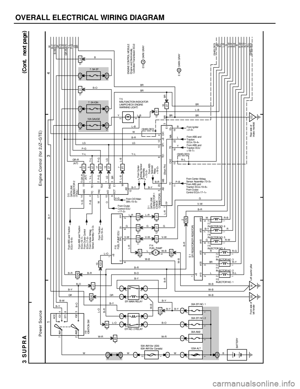
OVERALL ELECTRICAL WIRING DIAGRAM
1
234
3SUPRA(
Cont. next pa ge)
7ACC
IG1
ST1
IG2 AM1 4
8
3 2AM2
2 1
5 3 5
2 1
2
2 1J 4
22 22
224EA18EA15EA2
11IC2 12IC2 7IC2
2 BP15 4
M 6 BP1 9IJ1
4IB1
4 IJ1 12 IJ1 8 IJ1 IC210IJ16
IJ15
IJ117
IJ113
IF17
EA22 1B 4
22 22
EB BI1 2
1 2
1 2
1 2
1 2
1 2
Left quarter pillar Fr ont side of
left fender
120A ALT30A EFI NO. 2 30A EFI NO. 1
30A AM2
50A AM1(
for USA)
60A AM1(
for Canada)
15 II113 I I1 13 I J2 1J 51J31J6
1E 12
IJ118
ED Rear side of
intake manifold10A GAUGE7. 5A IGN7. 5A ST
B±O
B±RL±O
W± B
B±R L±RO W P±B V±G
L±BBRLG P± GY± L GR±R
L±RY±L
P±G
LG
L±B
B±R W± B8 562
15 16 22 1523 8 12 9 110 174 14
128 3 7 2
1 5
L±R
G
V± W
LW±BV± WGR± L YL
Y±LLG
L±R
G
V±W
L±OV± GB±Y B±YB±R
B±R B±R
B±O
B±Y
GR
B±W
B±YGR
B± Y
L±O
W± R W±R
WWB±OB± Y B±Y B±R
B± O
B± YW±B
3EFI NO. 2 REL AYEFI MAIN RELAY
(
Shor t Pin) EFPCDIFP
AB
OX2 TS
WA WB
F1 4
FUEL PUMP
D5
DA TA L I NK
CONNECTOR 2
(
TDCL)
D1
DA TA LI NK
CONNE CTOR 1
(
CHECK
CONNE CTOR)From ABS
Solenoid
Rel a y
< 19±2> ECT A/D TRC TC ABSFrom O/D Ma in
SW< 15±5>
Fr om Cr uise
Cont rol ECU
< 17±2>
From Traction
ECU< 19±4> From ABS and Traction
ECU< 19±7>
From Cr uise Control
ECU< 17±2>
From Center Air bag
Sens or As smbly< 13±3> Fr om ABS and Trac tion
ECU< 19±8>
W E1 ENGTE2 TE1TT
I19
IGNITION SW
F15
FUEL PUMP ECU +B
AB
234876 1
L BRR G B± YWR±B
R
R± W
R± G
R± Y
R± L
W± B
W± B
W± B
B B± R V±WG#10 #20 #30 #40 #50 #60S1
SFI RESISTOR(
EFI RESISTOR)I12
INJECTOR NO. 1 I13
INJECTOR NO. 2 I14
INJECTOR NO. 3 I15
INJECTOR NO. 4 I16
INJECTOR NO. 5 I17
INJECTOR NO. 6 (
SHI EL DED)
BATTERY+BFrom Center
Airbag Sens or
Assembly
< 13±3>
193
42LG P± GY± L GR±R(
A/T) B±R B±OGR B±W(
A/T) B±YW
BR BRBR
BR
W L±BL±BBR BR
B±OB
B T5
MAL FUNCT I ON I NDI CA TOR
LAMP(
CHECK ENGINE
WARNI NG LIGHT)
GR ±RY±L P±GLG
IG±(
SHI EL DED)
3 TE1 +B OX1
(
SHI ELDED)
(
SHI ELDED) R± L R± Y R± G R±WR R± B B± R V± WG L±B R± LBR
BR L±BBR
From Igniter
<2±2>
From ABS and
Trac tion ECU
< 19±7>
FP E1 1
1 111 2
222 2B±Y
B E 9 DARK GRAYA E1 0 DARK GRAY ENGINE CONTROL MODULE
(
Engine and Electr onic ally
Controlled Transmission ECU) 1E 81K4 5IB1
2A 1
From Center Airbag
Sensor Assembly< 13±3>
From ABS an d
Traction ECU< 19±8>
From Cruis e
Con t r o l E CU< 1 7± 1> P±B
11TC
From ABS and
Trac tion
ECU< 19±4>
13
VF 1
B± R Y
B±Y
2 2W
(
A/T)
Engine Control(
for 2JZ±GTE)
Power Source
(
A/T)