Page 295 of 878
C. Inspect VSV operation
(a) Check that air does not flow from port E to F.
(b) Apply battery voltage across the terminals.
(c) Check that air flows from port E to F.
If operation is not as specified, replace the VSV.
3. REINSTALL VSV
ENGINE COOLANT TEMPERATURE
(ECT) SENSOR
COMPONENTS FOR REMOVAL AND
INSTALLATION
± ENGINESFI SYSTEM (2JZ±GTE)EG±311
Page 330 of 878
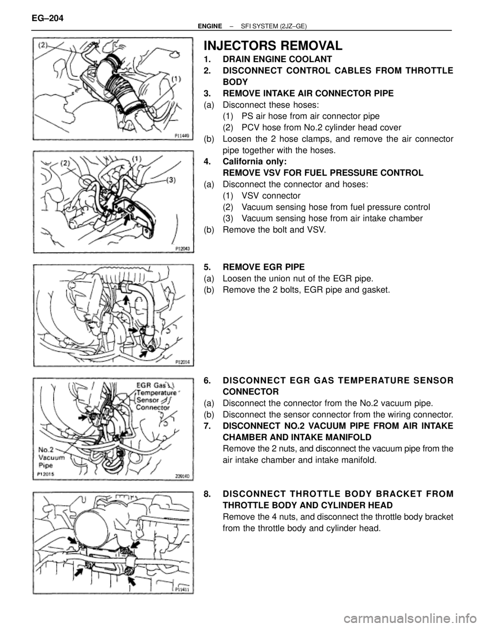
INJECTORS REMOVAL
1. DRAIN ENGINE COOLANT
2. DISCONNECT CONTROL CABLES FROM THROTTLE
BODY
3. REMOVE INTAKE AIR CONNECTOR PIPE
(a) Disconnect these hoses:
(1) PS air hose from air connector pipe
(2) PCV hose from No.2 cylinder head cover
(b) Loosen the 2 hose clamps, and remove the air connector
pipe together with the hoses.
4. California only:
REMOVE VSV FOR FUEL PRESSURE CONTROL
(a) Disconnect the connector and hoses:
(1) VSV connector
(2) Vacuum sensing hose from fuel pressure control
(3) Vacuum sensing hose from air intake chamber
(b) Remove the bolt and VSV.
5. REMOVE EGR PIPE
(a) Loosen the union nut of the EGR pipe.
(b) Remove the 2 bolts, EGR pipe and gasket.
6. DISCONNECT EGR GAS TEMPERATURE SENSOR
CONNECTOR
(a) Disconnect the connector from the No.2 vacuum pipe.
(b) Disconnect the sensor connector from the wiring connector.
7. DISCONNECT NO.2 VACUUM PIPE FROM AIR INTAKE
CHAMBER AND INTAKE MANIFOLD
Remove the 2 nuts, and disconnect the vacuum pipe from the
air intake chamber and intake manifold.
8. DISCONNECT THROTTLE BODY BRACKET FROM
THROTTLE BODY AND CYLINDER HEAD
Remove the 4 nuts, and disconnect the throttle body bracket
from the throttle body and cylinder head. EG±204
± ENGINESFI SYSTEM (2JZ±GE)
Page 368 of 878
ENGINE COOLANT TEMPERATURE
(ECT) SENSOR
COMPONENTS FOR REMOVAL AND
INSTALLATION
ECT SENSOR INSPECTION
1. DRAIN ENGINE COOLANT
2. REMOVE ECT SENSOR
(a) Disconnect the ECT sensor connector.
(b) Using SST, remove the ECT sensor and gasket.
SST 09205±76030 EG±242
± ENGINESFI SYSTEM (2JZ±GE)
Page 552 of 878
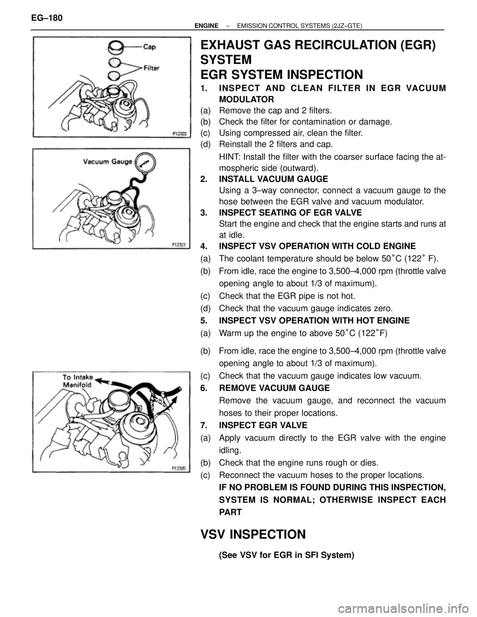
EXHAUST GAS RECIRCULATION (EGR)
SYSTEM
EGR SYSTEM INSPECTION
1. INSPECT AND CLEAN FILTER IN EGR VACUUM
MODULATOR
(a) Remove the cap and 2 filters.
(b) Check the filter for contamination or damage.
(c) Using compressed air, clean the filter.
(d) Reinstall the 2 filters and cap.
HINT: Install the filter with the coarser surface facing the at-
mospheric side (outward).
2. INSTALL VACUUM GAUGE
Using a 3±way connector, connect a vacuum gauge to the
hose between the EGR valve and vacuum modulator.
3. INSPECT SEATING OF EGR VALVE
Start the engine and check that the engine starts and runs at
at idle.
4. INSPECT VSV OPERATION WITH COLD ENGINE
(a) The coolant temperature should be below 50°C (122° F).
(b) From idle, race the engine to 3,500±4,000 rpm (throttle valve
opening angle to about 1/3 of maximum).
(c) Check that the EGR pipe is not hot.
(d) Check that the vacuum gauge indicates zero.
5. INSPECT VSV OPERATION WITH HOT ENGINE
(a) Warm up the engine to above 50°C (122°F)
(b) From idle, race the engine to 3,500±4,000 rpm (throttle valve
opening angle to about 1/3 of maximum).
(c) Check that the vacuum gauge indicates low vacuum.
6. REMOVE VACUUM GAUGE
Remove the vacuum gauge, and reconnect the vacuum
hoses to their proper locations.
7. INSPECT EGR VALVE
(a) Apply vacuum directly to the EGR valve with the engine
idling.
(b) Check that the engine runs rough or dies.
(c) Reconnect the vacuum hoses to the proper locations.
IF NO PROBLEM IS FOUND DURING THIS INSPECTION,
SYSTEM IS NORMAL; OTHERWISE INSPECT EACH
PART
VSV INSPECTION
(See VSV for EGR in SFI System) EG±180
± ENGINEEMISSION CONTROL SYSTEMS (2JZ±GTE)
Page 565 of 878
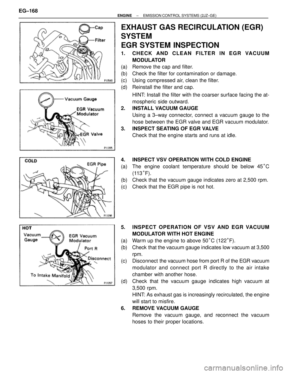
EXHAUST GAS RECIRCULATION (EGR)
SYSTEM
EGR SYSTEM INSPECTION
1. CHECK AND CLEAN FILTER IN EGR VACUUM
MODULATOR
(a) Remove the cap and filter.
(b) Check the filter for contamination or damage.
(c) Using compressed air, clean the filter.
(d) Reinstall the filter and cap.
HINT: Install the filter with the coarser surface facing the at-
mospheric side outward.
2. INSTALL VACUUM GAUGE
Using a 3±way connector, connect a vacuum gauge to the
hose between the EGR valve and EGR vacuum modulator.
3. INSPECT SEATING OF EGR VALVE
Check that the engine starts and runs at idle.
4. INSPECT VSV OPERATION WITH COLD ENGINE
(a) The engine coolant temperature should be below 45°C
(113°F).
(b) Check that the vacuum gauge indicates zero at 2,500 rpm.
(c) Check that the EGR pipe is not hot.
5. INSPECT OPERATION OF VSV AND EGR VACUUM
MODULATOR WITH HOT ENGINE
(a) Warm up the engine to above 50°C (122°F).
(b) Check that the vacuum gauge indicates low vacuum at 3,500
rpm.
(c) Disconnect the vacuum hose from port R of the EGR vacuum
modulator and connect port R directly to the air intake
chamber with another hose.
(d) Check that the vacuum gauge indicates high vacuum at
3,500 rpm.
HINT: As exhaust gas is increasingly recirculated, the engine
will start to misfire.
6. REMOVE VACUUM GAUGE
Remove the vacuum gauge, and reconnect the vacuum
hoses to their proper locations. EG±168
± ENGINEEMISSION CONTROL SYSTEMS (2JZ±GE)
Page 584 of 878
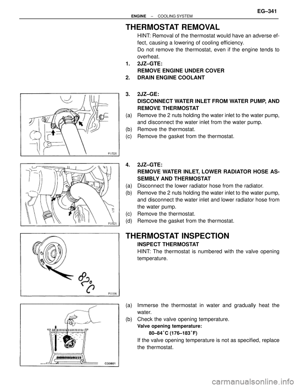
THERMOSTAT REMOVAL
HINT: Removal of the thermostat would have an adverse ef-
fect, causing a lowering of cooling efficiency.
Do not remove the thermostat, even if the engine tends to
overheat.
1. 2JZ±GTE:
REMOVE ENGINE UNDER COVER
2. DRAIN ENGINE COOLANT
3. 2JZ±GE:
DISCONNECT WATER INLET FROM WATER PUMP, AND
REMOVE THERMOSTAT
(a) Remove the 2 nuts holding the water inlet to the water pump,
and disconnect the water inlet from the water pump.
(b) Remove the thermostat.
(c) Remove the gasket from the thermostat.
4. 2JZ±GTE:
REMOVE WATER INLET, LOWER RADIATOR HOSE AS-
SEMBLY AND THERMOSTAT
(a) Disconnect the lower radiator hose from the radiator.
(b) Remove the 2 nuts holding the water inlet to the water pump,
and disconnect the water inlet and lower radiator hose from
the water pump.
(c) Remove the thermostat.
(d) Remove the gasket from the thermostat.
THERMOSTAT INSPECTION
INSPECT THERMOSTAT
HINT: The thermostat is numbered with the valve opening
temperature.
(a) Immerse the thermostat in water and gradually heat the
water.
(b) Check the valve opening temperature.
Valve opening temperature:
80±84°C (176±183°F)
If the valve opening temperature is not as specified, replace
the thermostat.
± ENGINECOOLING SYSTEMEG±341
Page 590 of 878
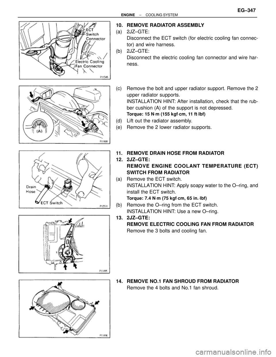
10. REMOVE RADIATOR ASSEMBLY
(a) 2JZ±GTE:
Disconnect the ECT switch (for electric cooling fan connec-
tor) and wire harness.
(b) 2JZ±GTE:
Disconnect the electric cooling fan connector and wire har-
ness.
(c) Remove the bolt and upper radiator support. Remove the 2
upper radiator supports.
INSTALLATION HINT: After installation, check that the rub-
ber cushion (A) of the support is not depressed.
Torque: 15 NVm (155 kgfVcm, 11 ftVlbf)
(d) Lift out the radiator assembly.
(e) Remove the 2 lower radiator supports.
11. REMOVE DRAIN HOSE FROM RADIATOR
12. 2JZ±GTE:
REMOVE ENGINE COOLANT TEMPERATURE (ECT)
SWITCH FROM RADIATOR
(a) Remove the ECT switch.
INSTALLATION HINT: Apply soapy water to the O±ring, and
install the ECT switch.
Torque: 7.4 NVm (75 kgfVcm, 65 in.Vlbf)
(b) Remove the O±ring from the ECT switch.
INSTALLATION HINT: Use a new O±ring.
13. 2JZ±GTE:
REMOVE ELECTRIC COOLING FAN FROM RADIATOR
Remove the 3 bolts and cooling fan.
14. REMOVE NO.1 FAN SHROUD FROM RADIATOR
Remove the 4 bolts and No.1 fan shroud.
± ENGINECOOLING SYSTEMEG±347
Page 596 of 878
ELECTRIC COOLING FAN (2JZ±GTE)
On±Vehicle Inspection
1. C H E C K C O O L I N G FA N O P E R AT I O N W I T H L O W
TEMPERATURE (Below 88°C (190°F))
(a) Turn the ignition switch ON.
(b) Check that the cooling fan stops.
If not, check the cooling fan relay and ECT switch, and check
for a separated connector or severed wire between the No.1
radiator fan relay and ECT switch.
(c) Disconnect the ECT switch connector.
(d) Check that the cooling fan rotates.
If not, check the No.1 radiator relay, No.2 radiator fan relay,
cooling fan, fuses, and check for short circuit between the
No.1 radiator fan relay and ECT switch.
(e) Reconnect the ECT switch connector.
2. CHECK COOLING FAN OPERATION WITH HIGH
TEMPERATURE (Above 97°C (207°F))
(a) Start the engine, and raise coolant temperature to above
97°C (207°F).
(b) Check that the cooling fan rotates.
If not, replace the ECT switch.
± ENGINECOOLING SYSTEMEG±353