Page 65 of 878

Check main heated oxygen")
Disconnect main heated oxygen sensor connector.
Measure resistance between terminals 1 and 2 of
main heated oxygen sensor connector.
Resistance: 11 Ð 16 � at 20°C (68°F)
Check main heated oxygen sensor heater.
Replace main heated oxygen sensor.
Check and repair harness or connector between
main relay and main heated oxygen sensor, main
heated oxygen sensor and engine control module.
Warm up engine to normal operating temperature.
Measure voltage between terminals HT1 of engine
control module connector and body ground, when
engine is idling and racing at 4,000 rpm.
Check voltage between terminals HT1 of engine control module connector
and body ground.
Replace main heated oxygen sensor.*
Check and replace engine control module.
In the 4,000 rpm racing check, continue engine
racing at 4,000 rpm for approx. 20 seconds or
more.
*: It is probable the oxygen sensor has deteri±
orated. Usually, this cannot be confirmed by
visual inspection. EG±528
± ENGINE2JZ±GTE ENGINE TROUBLESHOOTING
Page 75 of 878
.
EG±261
IG±21
EG±568
EG±583
EG±530
EG±532
EG±544
EG±33
Check each circuit found to be a possible cause of trouble according to the results of the check in
Check each item foun")
(See page EG±9).
EG±261
IG±21
EG±568
EG±583
EG±530
EG±532
EG±544
EG±33
Check each circuit found to be a possible cause of trouble according to the results of the check in
Check each item found to be a possible cause of problem.
Check for open and short in harness and connector between engine
control module and main heated oxygen sensor, engine control module
and data link connector 1 (See page IN±30).
The numbers int he table below show the order in which the checks should be done.
Repair or replace harness or connector.
Repair or replace.
Replace main heated oxygen sensor.
Repair or replace.
Check and replace engine control module.
Check compression (See page EG±9).
Does malfunction disappear when a good main heated oxygen sensor is
installed?
Faulty sensor installation
Air leakage
Misfire
Fuel system
Injector circuit
Characteristics deviation
in engine coolant temp. sensor
Characteristics deviation
in intake air temp. sensor
Characteristics deviation in mass
air flow meter
Va l v e t i m i n g
Main heater oxygen sensor signal
continues at 0 V
EG±538± ENGINE2JZ±GTE ENGINE TROUBLESHOOTING
Page 76 of 878
EG±583
IG±21
EG±33
EG±261
EG±568
EG±544
EG±530
EG±532
EG±9).
Check each circuit found to be a possible cause of trouble according to the results of the check in
Check each item found to be a possible cause of problem.
The numbers int he table below show the order in which the checks should be done.
Air leakage
Misfire
Fuel system
Injector circuit
Characteristics deviation
in engine coolant temp. sensor
Characteristics deviation
in intake air temp. sensor
Characteristics deviation in mass
air flow meter
Va l v e t i m i n g
Main heater oxygen sensor signal
continues at 5.0 VMain heater oxygen sensor
signal is normal
Check compression (See page EG±9).
Repair or replace.
Repair or replace.
Repair main heated oxygen sensor.
Check and replace engine control module.
Does malfunction disappear when a good main heated oxygen sensor is
installed?
± ENGINE2JZ±GTE ENGINE TROUBLESHOOTINGEG±539
Page 77 of 878

DTC 27 Sub Heated Oxygen Sensor Circuit
CIRCUIT DESCRIPTION
The sub heated oxygen sensor is installed on the exhaust pipe. Its construction and operation is the same as
the main heated oxygen sensor on page EG±525.
����� �
���� �����DTC No.���������������� �
��������������� ����������������Diagnostic Trouble Code Detecting Condition����������������� �
���������������� �����������������Trouble Area
����� �
���� �
���� �
���� �����
���������������� �
��������������� �
��������������� �
��������������� ����������������
(1) Open or short in heater circuit of sub
heated oxygen sensor for 0.5 sec. or more
����������������� �
���������������� �
���������������� �
���������������� �����������������
�Open or short in heater circuit of sub heated
oxygen sensor
�Sub heated oxygen sensor heater
�ECM
����� �
���� �
���� �
���� �
���� �
���� �
���� �
���� �
���� �����
27
���������������� �
��������������� �
��������������� �
��������������� �
��������������� �
��������������� �
��������������� �
��������������� �
��������������� ����������������
(2) Main heated oxygen sensor signal is 0.45 V
or more and sub heated oxygen sensor
signal is 0.45 V or less under conditions
(a) ~ (c):
(2 trip detection logic).*
(a) Engine coolant temp.: 805C (1765F)
or more
(b) Engine speed: 1,500 rpm or more
(c) Accel. pedal: Fully depressed for 2
sec. or more����������������� �
���������������� �
���������������� �
���������������� �
���������������� �
���������������� �
���������������� �
���������������� �
���������������� �����������������
�Open or short in sub heated oxygen sensor
circuit
�Sub heated oxygen sensor
�ECM
*: See page EG±503. EG±540
± ENGINE2JZ±GTE ENGINE TROUBLESHOOTING
Page 80 of 878
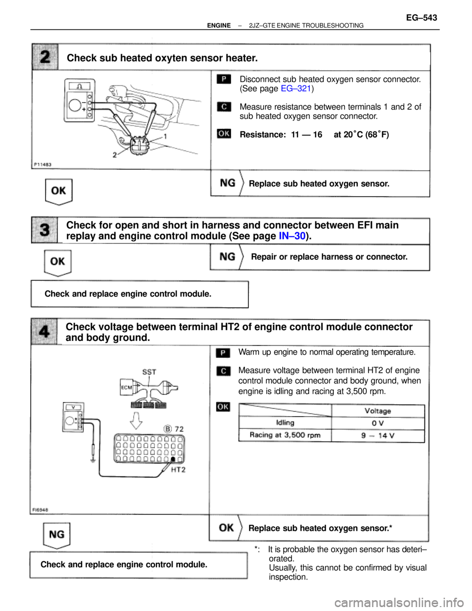
(See page EG±321)
Disconnect sub heated oxygen sensor connector.
(See page EG±321)
Measure resistance between terminals 1 and 2 of
sub heated oxygen sensor connector.
Resistance: 11 Ð 16 � at 20°C (68°F)
Check for open and short in harness and connector between EFI main
replay and engine control module (See page IN±30).
Check sub heated oxyten sensor heater.
Replace sub heated oxygen sensor.
Repair or replace harness or connector.
Check and replace engine control module.
Check voltage between terminal HT2 of engine control module connector
and body ground.
Replace sub heated oxygen sensor.*
Check and replace engine control module.
Warm up engine to normal operating temperature.
Measure voltage between terminal HT2 of engine
control module connector and body ground, when
engine is idling and racing at 3,500 rpm.
*: It is probable the oxygen sensor has deteri±
orated.
Usually, this cannot be confirmed by visual
inspection.
± ENGINE2JZ±GTE ENGINE TROUBLESHOOTINGEG±543
Page 115 of 878
Check for short in the harness and all the compo-
nents connected to IGN fuse (See Electrical Wir-
ing Diagram).
Remove IGN fuse from J/B No.1.
Check continuity of IGN fuse.
Continuity
Check IGN fuse.
Check ignition switch.
(1) Remove finish lower panel and finish lower
panel LH.
(2) Remove heater to register duct No.2.
Check continuity between terminals.
Check and repair harness and connector between
battery and ignition switch, ignition switch and en-
gine control module.
Replace ignition switch.
Terminal
Switch position
LOCK
ACC
ON
START
continuity
EG±578± ENGINE2JZ±GTE ENGINE TROUBLESHOOTING
Page 144 of 878

DIAGNOSTIC TROUBLE CODE CHART
HINT: Parameters listed in the chart may not be exactly the same as your reading due to type of the instruments
or other factors.
~
DTC
No.Number of
MIL BlinksCircuitDiagnostic Trouble Code Detecting Condition
NormalNo code is recorded.
G, NE Signal
(No.1)
G, NE Signal
(No.2)
Ignition Signal
A/T Control
Signal
(Main heated *3)
Oxygen
Sensor Signal
(Fr)
No NE or G1 and G2 signal to ECM for 2 sec. or more after cranking
Open in ªG �º circuit
No NE signal to ECM for 0.1 sec. or more at 1,000 rpm or more
NE signal does not pulse 12 times to ECM during the interval between
G1 and G2 pulses
No IGF signal to ECM for 6 consecutive IGT signals
Fault in communications between the engine CPU and A/T CPU in the
ECM
(1)*3Open or short in heater circuit of main heated oxygen sensor (Fr)
for 0.5 sec. or more
(2) (Main heated*3) oxygen sensor (Fr) signal voltage is reduced to
between 0.35 V and 0.70 V for 90 sec. under conditions
(a) ~ (d):
(2 trip detection logic)*4
(a) Engine coolant temp.: Between 80°C (176°F) and
95°C (203°F)
(b) Engine speed: 1,500 rpm or more
(c) Load driving (example A/T in in Overdrive, (5th for M/T),
A/C ON, Flat road, 80 km/H (50 mph))
(d) (Main heated*
3) oxygen sensor (Fr) signal voltage:
Alternating above and below 0.45 V
*3, 4: See page EG±396, 397. EG±388
± ENGINE2JZ±GE ENGINE TROUBLESHOOTING
Page 145 of 878
If a malfunction code is displayed during the diagnostic trouble code check in test mode, check the circuit for
that code listed in the table below (Proceed to the page given for that circuit).
EG±409
EG±412
EG±413
EG±418
EG±419
Malfunction
Indicator
Lamp*
1Trouble Area
Normal
ModeTest
Mode
See pageMemory*2
ON
ON
N.A.
N.A.
N.A.
N.A.
N.A.
N.A.
N.A.
ON
ON
ON
ON
� Open or short in NE, G circuit
� Distributor
� Open or short in STA circuit
� ECM
� Open or short in NE circuit
� Distributor
� ECM
� Open or short in NE circuit
� Distributor
� ECM
� Open or short in IGT or IGT circuit from igniter to ECM
� Igniter
� ECM
� ECM
� Open or short in heater circuit of main heated oxygen
sensor (Fr)
� Main heated oxygen sensor (Fr) heater
� ECM
� (Main heated*3) oxygen sensor (Fr) circuit
� (Main heated*3) oxygen sensor (Fr)
*1, 2, 3: See page EG±396
± ENGINE2JZ±GE ENGINE TROUBLESHOOTINGEG±389
.
Check each circuit found to be a possible cause of trouble according to the results of the check in
Check each item found to be a")
.
Remove IGN fuse from J/B No.1.
Check continuity of IGN fuse.
Continuity
Check IGN fuse.")
.
EG±40")