Page 2399 of 3115

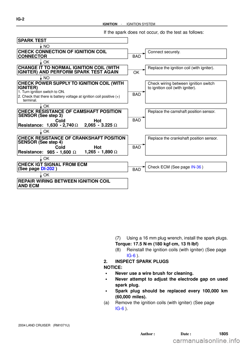
CHECK POWER SUPPLY TO IGNITION COIL (WITH
SENSOR (See step 3)
SPARK TEST
Replace the crankshaft position sensor.
CHECK RESISTANCE OF CAMSHAFT POSITION
1. Turn ignition switch to ON.
2. Check that there is battery voltage at ignition coil positive (+)
terminal.
CHECK CONNECTION OF IGNITION COIL
CONNECTOR
Resistance:Cold Hot
CHECK RESISTANCE OF CRANKSHAFT POSITION
Resistance:Cold Hot 1,630 - 2,740 W2,065 - 3.225 W
CHECK IGT SIGNAL FROM ECM
(See page DI-202)
REPAIR WIRING BETWEEN IGNITION COIL
AND ECM
Replace the camshaft position sensor. Connect securely.
Check wiring between ignition switch
to ignition coil (with igniter).
Check ECM (See page IN-36)
NO
OK
OK
OK
OKBAD
BAD
BAD
BAD
BAD
SENSOR (See step 4) IGNITER) CHANGE IT TO NORMAL IGNITION COIL (WITH
IGNITER) AND PERFORM SPARK TEST AGAIN
OKReplace the ignition coil (with igniter).
NO
OK
985 - 1,600 W1,265 - 1,890 W
IG-2
- IGNITIONIGNITION SYSTEM
1805 Author�: Date�:
2004 LAND CRUISER (RM1071U)
If the spark does not occur, do the test as follows:
(7) Using a 16 mm plug wrench, install the spark plugs.
Torque: 17.5 N´m (180 kgf´cm, 13 ft´lbf)
(8) Reinstall the ignition coils (with igniter) (See page
IG-6).
2. INSPECT SPARK PLUGS
NOTICE:
�Never use a wire brush for cleaning.
�Never attempt to adjust the electrode gap on used
spark plug.
�Spark plug should be replaced every 100,000 km
(60,000 miles).
(a) Remove the ignition coils (with igniter) (See page
IG-6).
Page 2448 of 3115

B16233
Recommended Viscosity (SAE):
TEMPERATURE RANGE ANTICIPATED BEFORE NEXT OIL CHANGE5W-30°C °F
-20
-290
-1820
-740
460
1680
27100
38
LU08N-04
B04468
Front
B04469
Oil Pressure Gauge
Oil Pressure Switch
P08343
Adhesive
- LUBRICATIONOIL AND FILTER
LU-1
1782 Author�: Date�:
2004 LAND CRUISER (RM1071U)
OIL AND FILTER
INSPECTION
1. CHECK ENGINE OIL QUALITY
Check the oil for deterioration, entry of water, discoloring or thin-
ning.
If the quality is visibly poor, replace the oil.
Oil grade:
API grade SL Energy-Conserving or ILSAC multi-
grade engine oil.
2. CHECK ENGINE OIL LEVEL
The oil level should be between the ºLº and ºFº marks on the dip-
stick.
If low, check for leakage and add oil up to the ºFº mark.
NOTICE:
�Do not fill with engine oil above the ºFº mark.
�Install the oil dipstick facing the direction shown in
the illustration.
3. REMOVE ENGINE UNDER COVER NO.1
4. REMOVE OIL PRESSURE SWITCH
5. INSTALL OIL PRESSURE GAUGE
6. WARM UP ENGINE
Allow the engine to warm up to normal operating temperature.
7. CHECK OIL PRESSURE
Oil pressure:
At idle: 29 kPa (0.3 kgf/cm
2, 4.2 psi) or more
At 3,000 rpm:
294 - 588 kPa (3.0 - 6.0 kgf/cm
2,
43 - 85 psi)
8. REMOVE OIL PRESSURE GAUGE
9. REINSTALL OIL PRESSURE SWITCH
(a) Apply adhesive to 2 or 3 threads of the oil pressure switch.
Adhesive:
Part No. 08833-00080, THREE BOND 1344, LOCTITE
242 or equivalent
(b) Reinstall the oil pressure switch.
10. START ENGINE, AND CHECK FOR ENGINE OIL
LEAKS
11. REINSTALL ENGINE UNDER COVER NO.1
Page 2450 of 3115

B04482
SST
B04483
B04484
SST
3/4 Turn
- LUBRICATIONOIL AND FILTER
LU-3
1784 Author�: Date�:
2004 LAND CRUISER (RM1071U)
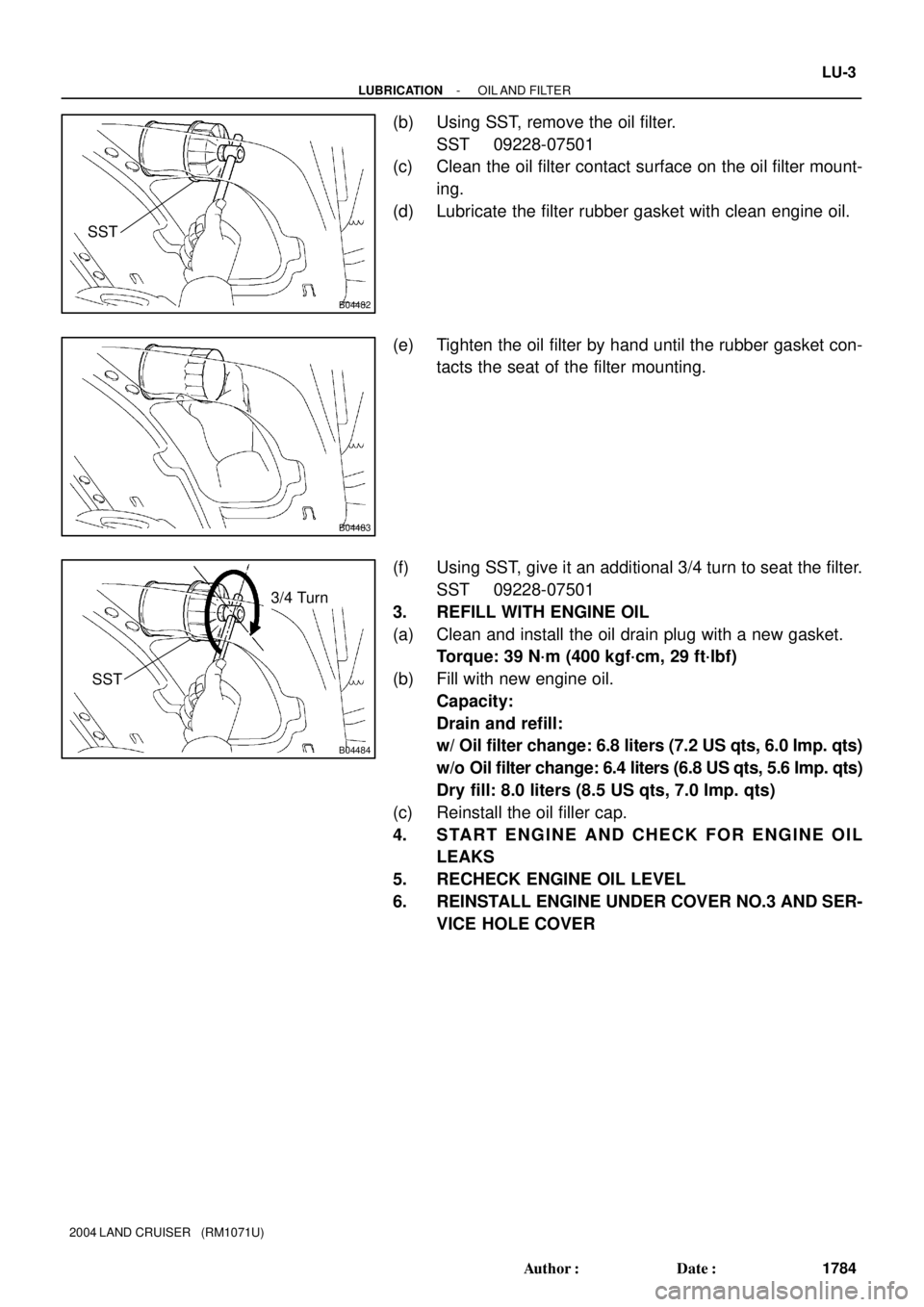
(b) Using SST, remove the oil filter.
SST 09228-07501
(c) Clean the oil filter contact surface on the oil filter mount-
ing.
(d) Lubricate the filter rubber gasket with clean engine oil.
(e) Tighten the oil filter by hand until the rubber gasket con-
tacts the seat of the filter mounting.
(f) Using SST, give it an additional 3/4 turn to seat the filter.
SST 09228-07501
3. REFILL WITH ENGINE OIL
(a) Clean and install the oil drain plug with a new gasket.
Torque: 39 N´m (400 kgf´cm, 29 ft´lbf)
(b) Fill with new engine oil.
Capacity:
Drain and refill:
w/ Oil filter change: 6.8 liters (7.2 US qts, 6.0 Imp. qts)
w/o Oil filter change: 6.4 liters (6.8 US qts, 5.6 Imp. qts)
Dry fill: 8.0 liters (8.5 US qts, 7.0 Imp. qts)
(c) Reinstall the oil filler cap.
4. START ENGINE AND CHECK FOR ENGINE OIL
LEAKS
5. RECHECK ENGINE OIL LEVEL
6. REINSTALL ENGINE UNDER COVER NO.3 AND SER-
VICE HOLE COVER
Page 2473 of 3115

B06412
B06415
Drain Plug
B06413Drain Plug
- MAINTENANCECHASSIS
MA-9
57 Author�: Date�:
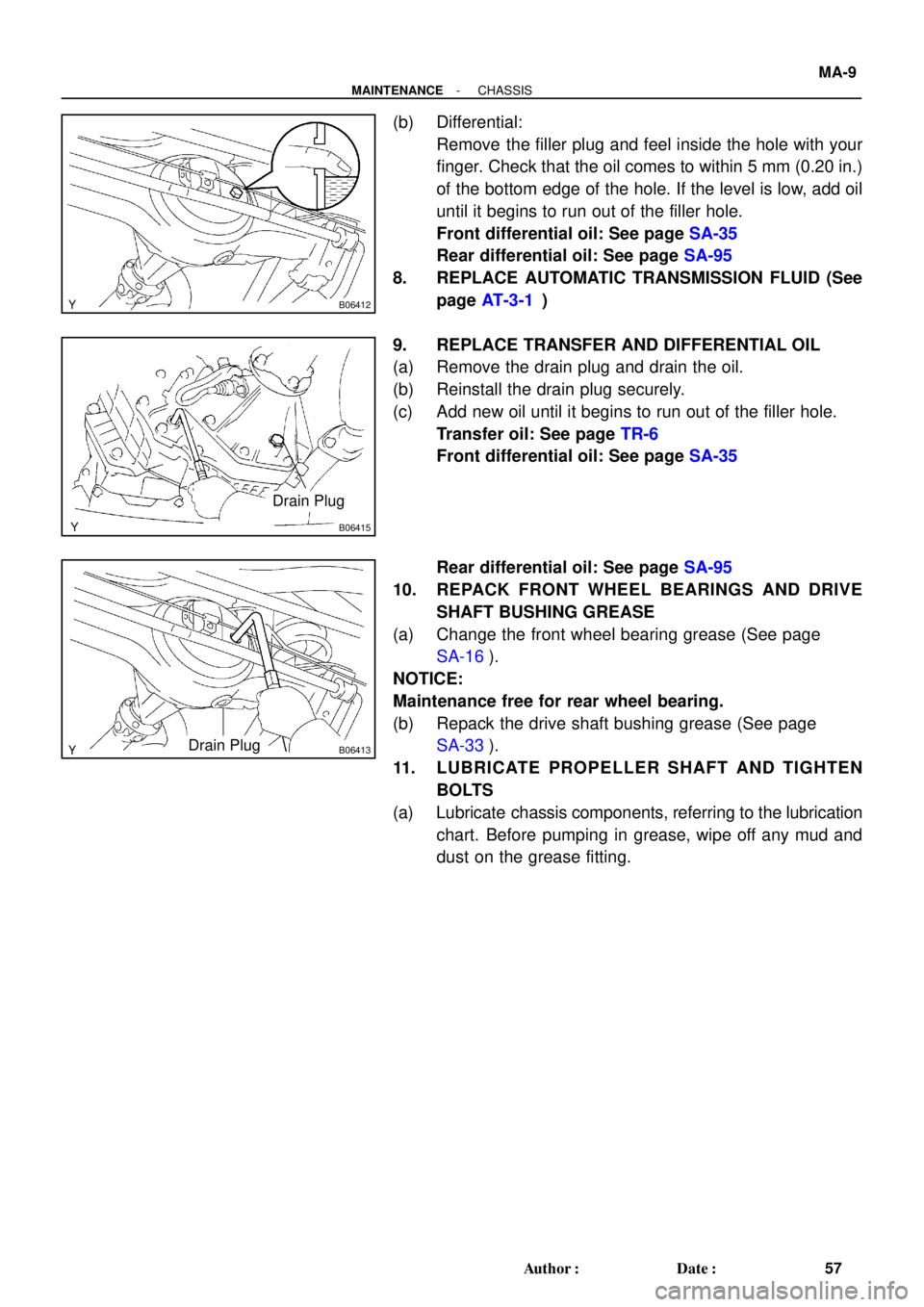
(b) Differential:
Remove the filler plug and feel inside the hole with your
finger. Check that the oil comes to within 5 mm (0.20 in.)
of the bottom edge of the hole. If the level is low, add oil
until it begins to run out of the filler hole.
Front differential oil: See page SA-35
Rear differential oil: See page SA-95
8. REPLACE AUTOMATIC TRANSMISSION FLUID (See
page AT-3-1)
9. REPLACE TRANSFER AND DIFFERENTIAL OIL
(a) Remove the drain plug and drain the oil.
(b) Reinstall the drain plug securely.
(c) Add new oil until it begins to run out of the filler hole.
Transfer oil: See page TR-6
Front differential oil: See page SA-35
Rear differential oil: See page SA-95
10. REPACK FRONT WHEEL BEARINGS AND DRIVE
SHAFT BUSHING GREASE
(a) Change the front wheel bearing grease (See page
SA-16).
NOTICE:
Maintenance free for rear wheel bearing.
(b) Repack the drive shaft bushing grease (See page
SA-33).
11. LUBRICATE PROPELLER SHAFT AND TIGHTEN
BOLTS
(a) Lubricate chassis components, referring to the lubrication
chart. Before pumping in grease, wipe off any mud and
dust on the grease fitting.
Page 2520 of 3115
PP1AW-07
PP-18
- PREPARATIONLUBRICATION
77 Author�: Date�:
2004 LAND CRUISER (RM1071U)
LUBRICANT
ItemCapacityClassification
Engine oil
Dry fill
Drain and refill
w/ Oil filter change
w/o Oil filter change
8.0 liters (8.5 US qts, 7.0 Imp. qts)
6.8 liters (7.2 US qts, 6.0 Imp. qts)
6.4 liters (6.8 US qts, 5.6 Imp qts)API grade SL Energy-Conserving or ILSAC mul-
tigrade engine oil.
Page 2649 of 3115
B16436
Battery
4 5
- SFIFUEL PUMP
SF-9
1708 Author�: Date�:
2004 LAND CRUISER (RM1071U)
Resistance: 0.2 - 3.0 W at 20°C (68°F)
If the resistance is not as specified, replace the fuel pump and/
or the lead wire.
(g) Inspect the fuel pump operation.
Connect the battery positive (+) lead to terminal 4 of the
connector, and the battery negative (-) lead to terminal 5.
Check that the fuel pump operates.
NOTICE:
�These tests must be done quickly (within 10 seconds)
to prevent the coil burning out.
�Keep the fuel pump as far away from the battery as
possible.
�Always change the connection on the battery side.
If operation is not as specified, replace the fuel pump and/or
lead wire.
(h) Reconnect the fuel pump & sender gauge connector.
(i) Reinstall the rear floor service hole cover with the 2
screws.
(j) Reinstall the front and rear floor carpets.
(k) Remove the 2 rear door scuff plates, the step plates and
the rear sear lock covers.
(l) Reinstall the No.1 rear seats.
Page 2830 of 3115

F04837
Fulcrum
Length
SST
F10803
SST
F04832
Vinyl Tape
F04824
SST
F04823
- STEERINGPOWER STEERING GEAR
SR-61
2270 Author�: Date�:
2004 LAND CRUISER (RM1071U)
(d) Using SST, torque the stopper.
SST 09922-10010
Torque: 110 N´m (1,122 kgf´cm, 81 ft´lbf)
NOTICE:
Use SST 09922-10010 in the direction shown in the illustra-
tion.
HINT:
Use a torque wrench with a fulcrum length of 380 mm (14.97
in.).
5. AIR TIGHTNESS TEST
(a) Install SST to the unions of the rack housing.
SST 09631-12071
(b) Apply 53 kPa (400 mmHg, 15.75 in.Hg) of vacuum for
about 30 seconds.
(c) Check that there is no change in the vacuum.
If there is change in the vacuum, check the installation of the oil
seals.
6. INSTALL CONTROL VALVE ASSEMBLY
(a) Coat the teflon rings with power steering fluid.
(b) To prevent oil seal lip damage, wind vinyl tape on the ser-
rated part of the control valve shaft.
(c) Push the valve assembly into the control valve housing.
NOTICE:
Be careful not to damage the teflon rings and oil seal lip.
(d) Coat a new O-ring with power steering fluid, and install
it to the bearing guide nut.
(e) Using SST, torque the nut.
SST 09631-20060
Torque: 24.5 N´m (250 kgf´cm, 18 ft´lbf)
NOTICE:
Be careful not to damage the oil seal lip.
(f) Using a punch, stake the nut.
Page 2915 of 3115

SA3102
SST
R13414
SST
SA2450
SST
SA2446
SA-50
- SUSPENSION AND AXLEFRONT DIFFERENTIAL CARRIER
2000 Author�: Date�:
2004 LAND CRUISER (RM1071U)
(b) Using SST and a press, install the front bearing onto the
drive pinion.
SST 09506-30012
7. TEMPORARILY ADJUST DRIVE PINION PRELOAD
(a) Install the drive pinion and rear bearing.
HINT:
Assemble the spacer and oil seal after adjusting the gear con-
tact pattern.
(b) Install the oil slinger.
(c) Using SST, install the companion flange.
SST 09950- 30012, (09951- 03010, 09953- 03010,
09954-03010, 09955-03030, 09956-03020)
(d) Using SST to hold the flange and adjust the drive pinion
preload by tightening the nut.
NOTICE:
�Coat the nut and threads of the drive pinion with gear
oil.
�As there is no spacer, tighten the nut a little at a time,
being careful not to overtighten.
(e) Using a torque wrench, measure the preload.
Preload (at starting):
New bearing
1.0 - 1.6 N´m (10 - 16 kgf´cm, 8.7 - 13.9 in.´lbf)
Reused bearing
0.5 - 0.8 N´m (5 - 8 kgf´cm, 4.3 - 6.9 in.´lbf)
HINT:
Measure the total preload after turning the bearing clockwise
and counterclockwise several times to make the bearing
smooth.
8. INSTALL DIFFERENTIAL CASE IN DIFFERENTIAL
CARRIER
(a) Place the bearing outer races on their respective bear-
ings. Check that the left and right outer races are not inter-
changed.
(b) Install the differential case in the differential carrier.