Page 412 of 3115

BO1KK-04
H18910
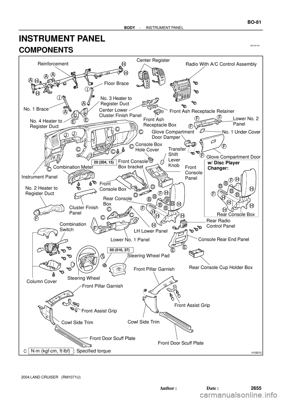
Reinforcement
Floor Brace
No. 1 BraceNo. 3 Heater to
Register Duct
Instrument PanelCenter Register
Radio With A/C Control Assembly
Front Ash Receptacle Retainer Center Lower
Cluster Finish Panel
Front Ash
Receptacle BoxLower No. 2
Panel
Glove Compartment Door
Rear Console Cup Holder Box Front
Console
Panel
Front
Console Box
Rear Console
Box
Rear Radio
Control Panel
Console Rear End Panel Combination Meter
Cluster Finish
Panel
LH Lower Panel
Lower No. 1 Panel No. 2 Heater to
Register Duct
Combination
Switch
Steering WheelSteering Wheel Pad
Front Pillar Garnish
Cowl Side Trim
Front Door Scuff Plate Front Assist Grip No. 4 Heater to
Register Duct
Front Pillar Garnish
Front Assist Grip
Cowl Side Trim
Front Door Scuff Plate
AA
A
A
BBB
C
C
C
C
CC
C
C
C
D
H
A
F
20 (204, 15)
EE
Glove Compartment
Door Damper
50 (510, 37)
BB
Rear Console BoxNo. 1 Under Cover
Console Box
Hole Cover
w/ Disc Player
Changer:
B
Column Cover
Transfer
Shift
Lever
Knob
: Specified torqueN´m (kgf´cm, ft´lbf)
H
H
H
H
I
I
EE
JJ
F
F
F
F
F
H
HH
H
H
BB
BB
HH
H
H
H
H
F
F
F
FF
D Front Console
Box bracket
- BODYINSTRUMENT PANEL
BO-81
2655 Author�: Date�:
2004 LAND CRUISER (RM1071U)
INSTRUMENT PANEL
COMPONENTS
Page 416 of 3115

BO3XU-02
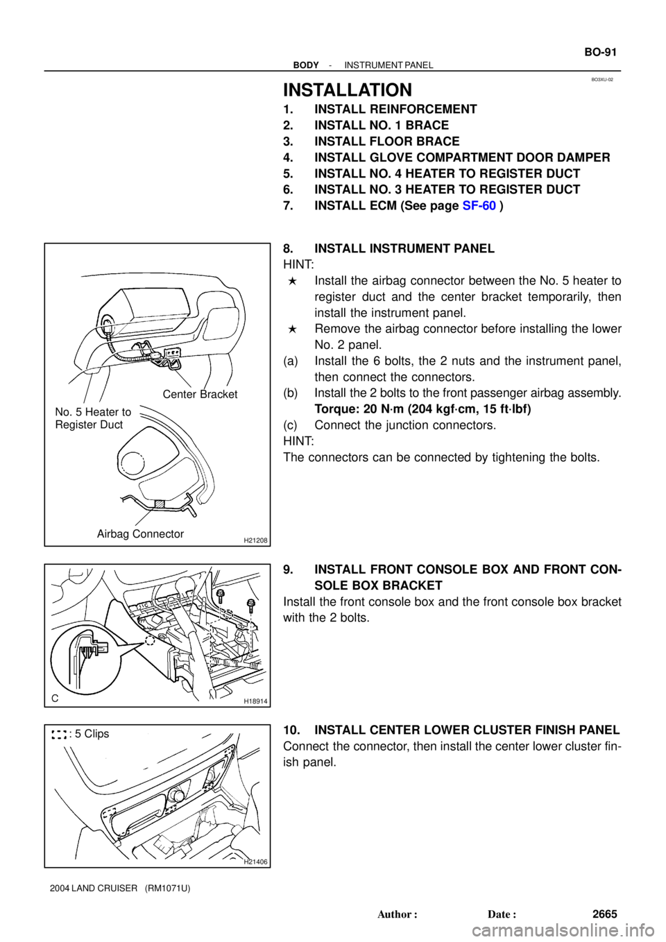
H21208
Center Bracket
No. 5 Heater to
Register Duct
Airbag Connector
H18914
H21406
: 5 Clips
- BODYINSTRUMENT PANEL
BO-91
2665 Author�: Date�:
2004 LAND CRUISER (RM1071U)
INSTALLATION
1. INSTALL REINFORCEMENT
2. INSTALL NO. 1 BRACE
3. INSTALL FLOOR BRACE
4. INSTALL GLOVE COMPARTMENT DOOR DAMPER
5. INSTALL NO. 4 HEATER TO REGISTER DUCT
6. INSTALL NO. 3 HEATER TO REGISTER DUCT
7. INSTALL ECM (See page SF-60)
8. INSTALL INSTRUMENT PANEL
HINT:
�Install the airbag connector between the No. 5 heater to
register duct and the center bracket temporarily, then
install the instrument panel.
�Remove the airbag connector before installing the lower
No. 2 panel.
(a) Install the 6 bolts, the 2 nuts and the instrument panel,
then connect the connectors.
(b) Install the 2 bolts to the front passenger airbag assembly.
Torque: 20 N´m (204 kgf´cm, 15 ft´lbf)
(c) Connect the junction connectors.
HINT:
The connectors can be connected by tightening the bolts.
9. INSTALL FRONT CONSOLE BOX AND FRONT CON-
SOLE BOX BRACKET
Install the front console box and the front console box bracket
with the 2 bolts.
10. INSTALL CENTER LOWER CLUSTER FINISH PANEL
Connect the connector, then install the center lower cluster fin-
ish panel.
Page 426 of 3115
H18914
H18915
BO-88
- BODYINSTRUMENT PANEL
2662 Author�: Date�:
2004 LAND CRUISER (RM1071U)
28. REMOVE FRONT CONSOLE BOX AND FRONT CON-
SOLE BOX BRACKET
Remove the 2 bolts, the front console box and the front console
box bracket.
29. REMOVE INSTRUMENT PANEL
(a) Disconnect the junction connectors.
HINT:
The connectors can be disconnected by loosening the bolts.
(b) Disconnect the connector, then remove the 8 bolts, the 2
nuts and the instrument panel.
30. REMOVE ECM (See page SF-60)
31. REMOVE NO. 3 HEATER TO REGISTER DUCT
32. REMOVE NO. 4 HEATER TO REGISTER DUCT
33. REMOVE GLOVE COMPARTMENT DOOR DAMPER
34. REMOVE FLOOR BRACE
35. REMOVE NO. 1 BRACE
36. REMOVE REINFORCEMENT
Page 1876 of 3115

EM-84
- ENGINE MECHANICALENGINE UNIT
1657 Author�: Date�:
2004 LAND CRUISER (RM1071U)
13. CONNECT HOSES, WIRES, CONNECTORS, CLAMPS,
GROMMET AND CABLES
(a) Connect the 2 PS air hoses to the hose clamp on the No.3
RH timing belt cover.
(b) Connect the generator wire.
(c) Connect the generator connector.
(d) Connect the hose clamp for the PS air hose.
(e) Connect the PS air hose to upper intake manifold.
(f) Connect the 2 heater hoses.
(g) Connect the engine wire clamp to the bracket on the cowl
panel.
(h) Connect the engine wire grommet to the cowl panel.
(i) Connect the ground strap connector.
(j) Connect the fuel main hose and the clamps.
(k) Connect the fuel return hose and the clamp.
(l) Connect the air inlet hose to the charcoal canister.
(m) Connect the EVAP hose to the charcoal canister.
(n) Connect the engine wire to the clamp on the right fender
apron.
(o) Connect the clamp on battery negative (-) cable to the
relay box.
(p) Connect the battery negative (-) cable to the right fender
apron.
(q) Connect the battery positive (+) terminal cable.
14. CONNECT ENGINE WIRE TO CABIN
(a) Connect the 3 wire harness connectors.
(b) Install the ECM with the 3 screws.
(c) Connect the 3 connectors to the ECM.
(d) Install the glove compartment door.
(e) Install the lower No.2 panel.
15. INSTALL FAN PULLEY, FAN, FLUID COUPLING AND
GENERATOR DRIVE BELT
(a) Temporarily install the fan pulley, the fan and the fluid cou-
pling assembly with the 4 nuts.
(b) Install the generator drive belt. (See page CH-16)
(c) Tighten the 4 nuts holding the fluid coupling to the fan
bracket.
16. INSTALL RADIATOR AND FAN SHROUD
(a) Place the fan shroud in the installation position.
(b) Install the radiator with the 2 support collars, the 2 nuts
and the 2 bolts.
(c) Connect the 2 A/T oil cooler hoses to the radiator.
(d) Install the lower radiator hose.
(e) Attach the lower side of the fan shroud to the brackets of
the radiator, and install the fan shroud with the 2 bolts.
(f) Install the 2 brackets on the wire to the radiator with the
2 bolts.
(g) Install the 2 clamps on the A/C discharge tube to the
brackets on the wire with the 2 nuts.
Page 1937 of 3115
2004 LAND CRUISER (EWD548U)
81 G
Connector Joining Wire Harness and Wire Harness
CodeJoining Wire Harness and Wire Harness (Connector Location)
IH2Instrument Panel Integration Wire and Column Wire (Near the Ignition SW)
II3
II4Dash Wire and Column Wire (Near the Ignition SW)
II5
(g)
IL3Instrument Panel Integration Wire and Computer Wire (Instrument Panel Center)
IM2Instrument Panel Integration Wire and Instrument Panel No.3 Wire (Right Side of Instrument Panel)
IN2Engine Wire and Dash Wire (Behind the Glove Box)
IP2Rear Console Box Wire and Dash Wire (Right Side of Rear Console)
IQ1Instrument Panel Integration Wire and Lamp Wire (Behind the Glove Box)
IT1Engine Room No.2 Wire and Dash Wire (Right Kick Panel)
Page 1939 of 3115
2004 LAND CRUISER (EWD548U)
83 G
Connector Joining Wire Harness and Wire Harness
CodeJoining Wire Harness and Wire Harness (Connector Location)
IU1
IU2Instrument Panel Integration Wire and Dash Wire (Behind the Glove Box)IU3Instrument Panel Integration Wire and Dash Wire (Behind the Glove Box)
IU4
IV3Dash Wire and Floor No 2 Wire (Right Kick Panel)IV4Dash Wire and Floor No.2 Wire (Right Kick Panel)
IW3Engine Room No.2 Wire and Dash Wire (Behind the Glove Box)
IX1Instrument Panel Integration Wire and Engine Wire (Behind the Glove Box)IX2Instrument Panel Integration Wire and Engine Wire (Behind the Glove Box)
IY2Front Door RH Wire and Dash Wire (Right Kick Panel)
Page 1941 of 3115
2004 LAND CRUISER (EWD548U)
85 G
Connector Joining Wire Harness and Wire Harness
CodeJoining Wire Harness and Wire Harness (Connector Location)
Ia1Dash Wire and Dash Wire (Behind the Combination Meter)
Ib1
Ib2Dash Wire and Dash Wire (Behind the Combination Meter)
Ib3
()
Ic2Dash Wire and Dash Wire (Behind the Center Panel)
Id1
Id2Dash Wire and Dash Wire (Instrument Panel Center)Id3Dash Wire and Dash Wire (Instrument Panel Center)
Id4
Ie1Dash Wire and Dash Wire (Behind the Glove Box)
If1Engine Wire and Engine Wire (Behind the Glove Box)
Ig1Dash Wire and Floor No.2 Wire (Right Side of Front Console)
Ih1Dash Wire and Dash Wire (Center Side of Front Console)
Page 1951 of 3115

2004 LAND CRUISER (EWD548U)
70G ELECTRICAL WIRING ROUTING
Position of Parts in Instrument Panel
A 14 Accel Position Sensor
A 18 A/C Solar Sensor
A 19 A/C Thermistor
A 24 Air Inlet Control Servo Motor
A 25 Air Mix Control Servo Motor
A 26 Air Vent Mode Control Servo Motor
A 27 Airbag Squib (Front Passenger Airbag Assembly)
A 28 Airbag Squib (Steering Wheel Pad)
A 29 Ashtray Illumination
A 30 Auto Antenna Control Relay
A 31 Automatic Light Control Sensor
A 41 ABS & BA & TRAC & VSC ECU
A 42 ABS & BA & TRAC & VSC ECU
A 43 ABS & BA & TRAC & VSC ECU
A 44 ABS & BA & TRAC & VSC ECU
A 45 A/C Control Assembly
A 46 A/C Control Assembly
A 47 A/C Control Assembly
A 48 A/T Shift Lever Illumination
Shift Lock Control ECU
B 1 Blower Motor Controller
B 7 Body ECU
B 8 Body ECU
B 9 Body ECU
C 5 Center Diff. Lock Control Relay
C 10 Cigarette LighterC 11 Cigarette Lighter Illumination
C 12 Combination Meter
C 13 Combination Meter
C 14 Combination Meter
C 15 Combination Meter
C 16 Combination SW
C 17 Combination SW
C 18 Combination SW
C 19 Combination SW
C 25 Center Airbag Sensor Assembly
C 26 Center Airbag Sensor Assembly
C 27 Center Airbag Sensor Assembly
C 28 Center Cluster Integration Panel
D 7 Data Link Connector 3
D 26 DVD Automatic Changer
E 4 Electronically Controlled Transmission Pattern Select SW
E 5 Engine Control Module
E 6 Engine Control Module
E 7 Engine Control Module
E 8 Engine Control Module
E 9 Engine Control Module
G 3 Glove Box Light
G 4 Gateway ECU
I 18 Ignition SW