Page 27 of 3115

AC1LQ-04
I08494
AC-90
- AIR CONDITIONINGAIR INLET TEMPERATURE SENSOR
2815 Author�: Date�:
2004 LAND CRUISER (RM1071U)
AIR INLET TEMPERATURE
SENSOR
INSPECTION
1. REMOVE FRONT SEATS
2. REMOVE REAR CONSOLE BOX
3. REMOVE FRONT CONSOLE BOX COVER
4. REMOVE LOWER CENTER CLUSTER FINISH PANEL
5. REMOVE FRONT DOOR SCUFF PLATES
6. REMOVE COWL SIDE TRIMS
7. REMOVE REAR DOOR SCUFF PATES
8. REMOVE CENTER PILLAR GARNISHES
9. REMOVE AIR INLET TEMPERATURE SENSOR
(a) Slide the floor carpet backward.
(b) Disconnect the connector.
(c) Remove the screw and the air inlet temperature sensor.
10. INSPECT AIR INLET TEMPERATURE SENSOR CIR-
CUIT (See page DI-1342)
11. INSTALL AIR INLET TEMPERATURE SENSOR
(a) Install the air inlet temperature sensor with the screw.
(b) Connect the connector.
(c) Install the floor carpet.
12. INSTALL CENTER PILLAR GARNISHES
13. INSTALL REAR DOOR SCUFF PLATES
14. INSTALL COWL SIDE TRIMS
15. INSTALL FRONT DOOR SCUFF PLATES
16. INSTALL REAR CONSOLE BOX
17. INSTALL FRONT SEATS
Page 81 of 3115

AC1LJ-04
I06818
- AIR CONDITIONINGPOWER TRANSISTOR (for Rear Heater)
AC-83
2808 Author�: Date�:
2004 LAND CRUISER (RM1071U)
POWER TRANSISTOR (for Rear
Heater)
INSPECTION
1. REMOVE FRONT SEATS
2. REMOVE REAR CONSOLE BOX
3. REMOVE FRONT CONSOLE BOX COVER
4. REMOVE LOWER CENTER CLUSTER FINISH PANEL
5. REMOVE FRONT DOOR SCUFF PLATES
6. REMOVE COWL SIDE TRIMS
7. REMOVE REAR DOOR SCUFF PATES
8. REMOVE CENTER PILLAR GARNISHES
9. REMOVE POWER TRANSISTOR
(a) Slide the floor carpet backward.
(b) Disconnect the connector.
(c) Remove the 2 screws and power transistor.
10. INSPECT POWER TRANSISTOR
Check the power transistor in the same way as for ºPOWER
TRANSISTOR (For Rear Cooler)º on page AC-82.
11. INSTALL POWER TRANSISTOR
12. INSTALL CENTER PILLAR GARNISHES
13. INSTALL REAR DOOR SCUFF PATES
14. INSTALL COWL SIDE TRIMS
15. INSTALL FRONT DOOR SCUFF PLATES
16. INSTALL LOWER CENTER CLUSTER FINISH PANEL
17. INSTALL FRONT CONSOLE BOX COVER
18. INSTALL REAR CONSOLE BOX
19. INSTALL FRONT SEATS
Page 109 of 3115
AC1KO-04
I03973
I05080
Second Ridge
Hose Clip
Water Hose
I03924
- AIR CONDITIONINGREAR HEATER UNIT
AC-47
2772 Author�: Date�:
2004 LAND CRUISER (RM1071U)
REMOVAL
1. DRAIN ENGINE COOLANT FROM RADIATOR
HINT:
It is not necessary to drain out all the coolant.
2. DISCONNECT WATER HOSES FROM HEATER RA-
DIATOR PIPES
(a) Using pliers, grip the claws of the clip and slide the clip
along the hose
(b) Disconnect the water hoses
HINT:
At the time of installation, push the water hose on to the heater
radiator pipe to the second ridge on the pipe.
3. REMOVE FRONT SEATS
4. REMOVE REAR CONSOLE BOX
5. REMOVE FRONT CONSOLE BOX COVER
6. REMOVE LOWER CENTER CLUSTER FINISH PANEL
7. REMOVE FRONT DOOR SCUFF PLATE
8. REMOVE COWL SIDE TRIMS
9. REMOVE REAR DOOR SCUFF PLATES
10. REMOVE CENTER PILLAR GARNISHES
11. SLIDE FLOOR CARPET BACKWARD
12. REMOVE COOLER BRACKET
Remove the 4 bolts and the cooler bracket.
Page 434 of 3115

BO4IW-01
H05257
: 5 Clips
H05258
H05259
H07941
11 Clips BO-62
- BODYQUARTER WINDOW GLASS
2636 Author�: Date�:
2004 LAND CRUISER (RM1071U)
REMOVAL
1. REMOVE ROOF HEADLINING REAR TRIM
Using a screwdriver, remove the roof headlining rear trim.
HINT:
Tape up the screwdriver tip before use.
2. REMOVE REAR NO. 2 SEATS
3. REMOVE REAR MAT SET PLATE
(a) Remove the 5 screws.
(b) Using a screwdriver, remove the rear mat set plate.
HINT:
Tape up the screwdriver tip before use.
4. REMOVE STRIKER PLATE
(a) Remove the 6 screws.
(b) Using a screwdriver, remove the striker plates.
HINT:
Tape up the screwdriver tip before use.
5. REMOVE REAR MAT
6. REMOVE REAR NO. 2 SEAT OUTER BELT FLOOR AN-
CHOR
Torque:42 N´m (430 kgf´cm, 31 ft´lbf)
7. REMOVE REAR NO. 1 SEAT OUTER BELT FLOOR AN-
CHOR
Torque:42 N´m (430 kgf´cm, 31 ft´lbf)
8. REMOVE REAR DOOR SCUFF PLATE
9. REMOVE REAR DOOR OPENING TRIM
10. REMOVE QUARTER TRIM PANEL
(a) Remove the quarter trim jack cover.
(b) Using a clip remover, remove the 2 clips.
(c) Remove the quarter trim panel, then disconnect the con-
nector.
11. REMOVE REAR NO. 2 SEAT OUTER BELT SHOUL-
DER ANCHOR
12. REMOVE REAR NO. 1 SEAT OUTER BELT SHOUL-
DER ANCHOR
Page 467 of 3115

BO4IZ-01
H05257
: 5 Clips
H05258
H05259
H07941
11 Clips
- BODYROOF HEADLINING
BO-97
2671 Author�: Date�:
2004 LAND CRUISER (RM1071U)
REMOVAL
1. REMOVE ROOF HEADLINING REAR TRIM
Using a screwdriver, remove the roof headlining rear trim.
HINT:
Tape up the screwdriver tip before use.
2. REMOVE REAR NO. 2 SEATS
3. REMOVE REAR MAT SET PLATE
(a) Remove the 5 screws.
(b) Using a screwdriver, remove the rear mat set plate.
HINT:
Tape up the screwdriver tip before use.
4. REMOVE STRIKER PLATES
(a) Remove the 6 screws.
(b) Using a screwdriver, remove the striker plates.
HINT:
Tape up the screwdriver tip before use.
5. REMOVE REAR MAT
6. REMOVE REAR NO. 2 SEAT OUTER BELT FLOOR AN-
CHOR
Torque: 42 N´m (430 kgf´cm, 31 ft´lbf)
7. REMOVE REAR NO. 1 SEAT OUTER BELT FLOOR AN-
CHOR
Torque: 42 N´m (430 kgf´cm, 31 ft´lbf)
8. REMOVE REAR DOOR SCUFF PLATES
9. REMOVE REAR DOOR OPENING TRIMS
10. REMOVE QUARTER TRIM PANEL LH
(a) Remove the quarter trim jack cover.
(b) Using a clip remover, remove the 2 clips.
(c) Remove the quarter trim panel LH, then disconnect the
connector.
Page 616 of 3115
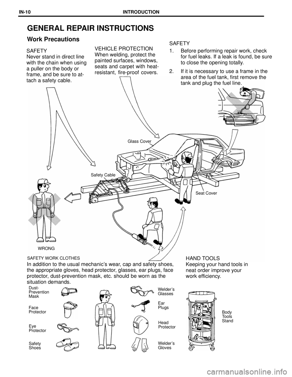
GENERAL REPAIR INSTRUCTIONS
Work PrecautionsSAFETY
1. Before performing repair work, check
for fuel leaks. If a leak is found, be sure
to close the opening totally.
2. If it is necessary to use a frame in the
area of the fuel tank, first remove the
tank and plug the fuel line. SAFETY
Never stand in direct line
with the chain when using
a puller on the body or
frame, and be sure to at-
tach a safety cable.VEHICLE PROTECTION
When welding, protect the
painted surfaces, windows,
seats and carpet with heat-
resistant, fire-proof covers.
Glass Cover
Safety Cable
Seat Cover
WRONG
SAFETY WORK CLOTHES
HAND TOOLS
Keeping your hand tools in
neat order improve your
work efficiency. In addition to the usual mechanic's wear, cap and safety shoes,
the appropriate gloves, head protector, glasses, ear plugs, face
protector, dust-prevention mask, etc. should be worn as the
situation demands.
Dust-
Prevention
MaskWelder's
Glasses
Ear
Plugs
Face
Protector
Body
Tools
Stand
Head
Protector Eye
Protector
Welder's
Gloves Safety
Shoes
INTRODUCTIONIN-10
Page 1831 of 3115
EM0L1-08
A03191
SST
A03192
EM-44
- ENGINE MECHANICALCYLINDER HEAD
1617 Author�: Date�:
2004 LAND CRUISER (RM1071U)
DISASSEMBLY
1. REMOVE VALVE LIFTERS AND SHIMS
HINT:
Arrange the valve lifters and the shims in correct order.
2. REMOVE VALVES
(a) Using SST, compress the valve spring and remove the 2
keepers.
SST 09202-70020
(b) Remove the spring retainer.
(c) Remove the valve spring.
(d) Remove the valve.
(e) Remove the spring seat.
HINT:
Arrange the valves, the valve springs, the spring seats and the
spring retainers incorrect order.
(f) Using needle-nose pliers, remove the oil seal.
Page 2648 of 3115
B16435
Ohmmeter
5
4
SF-8
- SFIFUEL PUMP
1707 Author�: Date�:
2004 LAND CRUISER (RM1071U)
Fuel pressure:
265 - 304 kPa (2.7 - 3.1 kgf/cm
2, 38 - 44 psi)
If pressure is higher than the specification, replace the fuel
pressure regulator.
If pressure is lower than the specification, check these parts:
�Fuel hoses and connections
�Fuel pump
�Fuel filter
�Fuel pressure regulator
(i) Disconnect the TOYOTA hand- held tester from the
DLC3.
(j) Start the engine.
(k) Measure the fuel pressure at idle.
Fuel pressure:
265 - 304 kPa (2.7 - 3.1 kgf/cm
2, 38 - 44 psi)
(l) Stop the engine.
(m) Check that the fuel pressure remains in the specification
below for 5 minutes after the engine stop.
Fuel pressure:
147 kPa (1.5 kgf/cm
2, 21 psi) or more
If the pressure is not as specified, check the fuel pump, pres-
sure regulator and/or the injectors.
(n) After checking the fuel pressure, disconnect the negative
(-) terminal cable from the battery and carefully remove
the SST to prevent gasoline from splashing.
SST 09268-45014
(o) Reinstall the front fuel pipe to the LH delivery pipe (See
page SF-27).
(p) Reconnect the negative (-) terminal cable to the battery.
(q) Check for fuel leaks (See page SF-1).
(r) Reinstall the V-bank cover with the 2 bolts and nuts.
(s) Reconnect the fuel return hose to the clamp on the V-
bank cover.
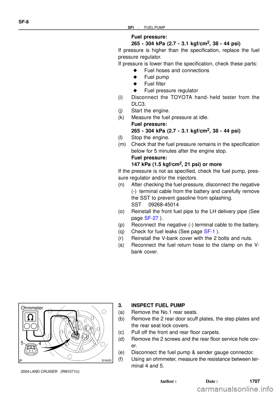
3. INSPECT FUEL PUMP
(a) Remove the No.1 rear seats.
(b) Remove the 2 rear door scuff plates, the step plates and
the rear seat lock covers.
(c) Pull off the front and rear floor carpets.
(d) Remove the 2 screws and the rear floor service hole cov-
er.
(e) Disconnect the fuel pump & sender gauge connector.
(f) Using an ohmmeter, measure the resistance between ter-
minal 4 and 5.