Page 883 of 3115
AB0119S08096F00446
E1
Ts DLC1 ON
(-)
(+)
DI-654- DIAGNOSTICSABS & VEHICLE STABILITY CONTROL (VSC) &
BRAKE ASSIST (BA) SYSTEM
847 Author�: Date�:
2004 LAND CRUISER (RM1071U)
INSPECTION PROCEDURE
1 Check voltage between terminals Ts and E1 of DLC1.
CHECK:
(a) Turn the ignition switch ON.
(b) Measure voltage between terminals Ts and E
1 of the
DLC1.
OK:
Voltage: 10 to 14 V
OK If ABS warning light does not blink even after Ts
and E
1 are connected, the ECU may be defec-
tive.
NG
2 IG switch OFF, and check for open and short circuit in harness and connector
between skid control ECU and DLC1, DLC1 and body ground (See page IN-36
).
NG Repair or replace harness or connector.
OK
Check and replace skid control ECU.
Page 884 of 3115
F17756
ABS & BA & TRAC
& VSC ECU
Cowl Side J/B RH Cowl Side J/B RH
Cowl Side J/B RH
I18
Ignition SW
Engine Room J/BCowl Side J/B LHCombination Meter
Cowl Side J/B LH
IG1 No.2 Relay
J/B No.2
MAIN
FL Block ECD4 Detection SW
(Center Diff. Lock)
BatteryVSC OFF
IFEC EXI
IG2
IG1
WT A43
A44
A42
A43 IX1
IGN
MET
IG1
AM2
AM1 ECU-IG1
ALTP-B
B-R
B-W
L-R
SB
BR SB
IX1
W-R B-R
SB
B-R
B-R L-B
B-R W-R
W-R
B-G
B-G3
A
AJ4
J/C
C15
C12
C13 3E
3B
3Q3Q
3B
3Q 3B
1C 1B 2A 2E
2E
2E 2B
2C
F1522
6
7 26
14 56
3 SB2
P-B
422
7
2
74
6
1910 41
2
1
5 37
18
391
217 101 W-B
IG2 AM1
AM28 2 1
3
F161
- DIAGNOSTICSABS & VEHICLE STABILITY CONTROL (VSC) &
BRAKE ASSIST (BA) SYSTEMDI-645
838 Author�: Date�:
2004 LAND CRUISER (RM1071U)
VSC OFF Indicator Light, Center Diff Lock Switch Circuit
CIRCUIT DESCRIPTION
This is the VSC control main switch. When the center differential is locked, VSC control goes off and the VSC
OFF indicator light lights up.
WIRING DIAGRAM
DICAA-02
Page 885 of 3115
DI-646- DIAGNOSTICSABS & VEHICLE STABILITY CONTROL (VSC) &
BRAKE ASSIST (BA) SYSTEM
839 Author�: Date�:
2004 LAND CRUISER (RM1071U)
INSPECTION PROCEDURE
HINT:
Start the inspection from step 1 in case of using the hand-held tester and start from step 2 in case of not
using the hand-held tester.
1 Check operation of the VSC OFF indicator light.
PREPARATION:
(a) Connect the hand-held tester to the DLC3.
(b) Turn the ignition switch ON and push the hand-held tester main switch ON.
(c) Select the ACTIVE TEST mode on the hand-held tester.
CHECK:
Check that ºONº and ºOFFº of the VSC OFF indicator light can be shown on the combination meter with the
hand-held tester.
NG Go to step 3.
OK
2 Is DTC output for VSC?
YES Repair circuit indicated by the output code.
NO
3 Does the warning lights other than VSC OFF indicator light come on?
YES Go to step 5.
NO
Page 888 of 3115
F17765
ABS & BA & TRAC
& VSC ECU
Engine Room J/B Combination Meter
Cowl Side J/B RH
Cowl Side J/B LH
I18
Ignition SW
Cowl Side J/B RHVSCW 4
A43 18
3B 27
3Q
16
C13
41
2E10
2A1B9
1
1C AM2
W-R B-R
C12
C15
ECSB
BR8
IX1 3Q SB7MET
4
3EB-R
B-G
FL Block SB L-W
W-R
76 AM2 IG2
J4
J/C
AA
2
F15Battery 1 10 VSC TRAC
MAIN
- DIAGNOSTICSABS & VEHICLE STABILITY CONTROL (VSC) &
BRAKE ASSIST (BA) SYSTEMDI-631
824 Author�: Date�:
2004 LAND CRUISER (RM1071U)
VSC TRAC Warning Light Circuit
CIRCUIT DESCRIPTION
If the ECU stores DTC, the VSC TRAC warning light illuminates the combination meter.
WIRING DIAGRAM
DICA6-02
Page 889 of 3115

DI-632- DIAGNOSTICSABS & VEHICLE STABILITY CONTROL (VSC) &
BRAKE ASSIST (BA) SYSTEM
825 Author�: Date�:
2004 LAND CRUISER (RM1071U)
INSPECTION PROCEDURE
HINT:
Troubleshoot in accordance with the table below for each trouble symptom.
VSC TRAC warning light does not light up*1
VSC TRAC warning light remains on*2
*1: Start the inspection from step 1 in case of using the hand-held tester and start from step 2 in case of not
using the hand-held tester.
*
2: After inspection with step 4, start the inspection from step 5 in case of using the hand-held tester and
start from step 6 in case of not using hand-held tester.
1 Check operation of the VSC TRAC warning light.
PREPARATION:
(a) Connect the hand-held tester to the DLC3.
(b) Turn the ignition switch ON and push the hand-held tester main switch ON.
(c) Select the ACTIVE TEST mode on the hand-held tester.
CHECK:
Check that ºONº and ºOFFº of the VSC TRAC warning light can be shown on the combination meter on the
hand-held tester.
OK Check and replace skid control ECU.
NG
2 Does the warning lights other than VSC TRAC warning light come on?
YES Repair VSC TRAC warning light bulb or com-
bination meter assembly.
NO
Page 894 of 3115

DIC8V-01
DI-518- DIAGNOSTICSABS & VEHICLE STABILITY CONTROL (VSC) &
BRAKE ASSIST (BA) SYSTEM
711 Author�: Date�:
2004 LAND CRUISER (RM1071U)
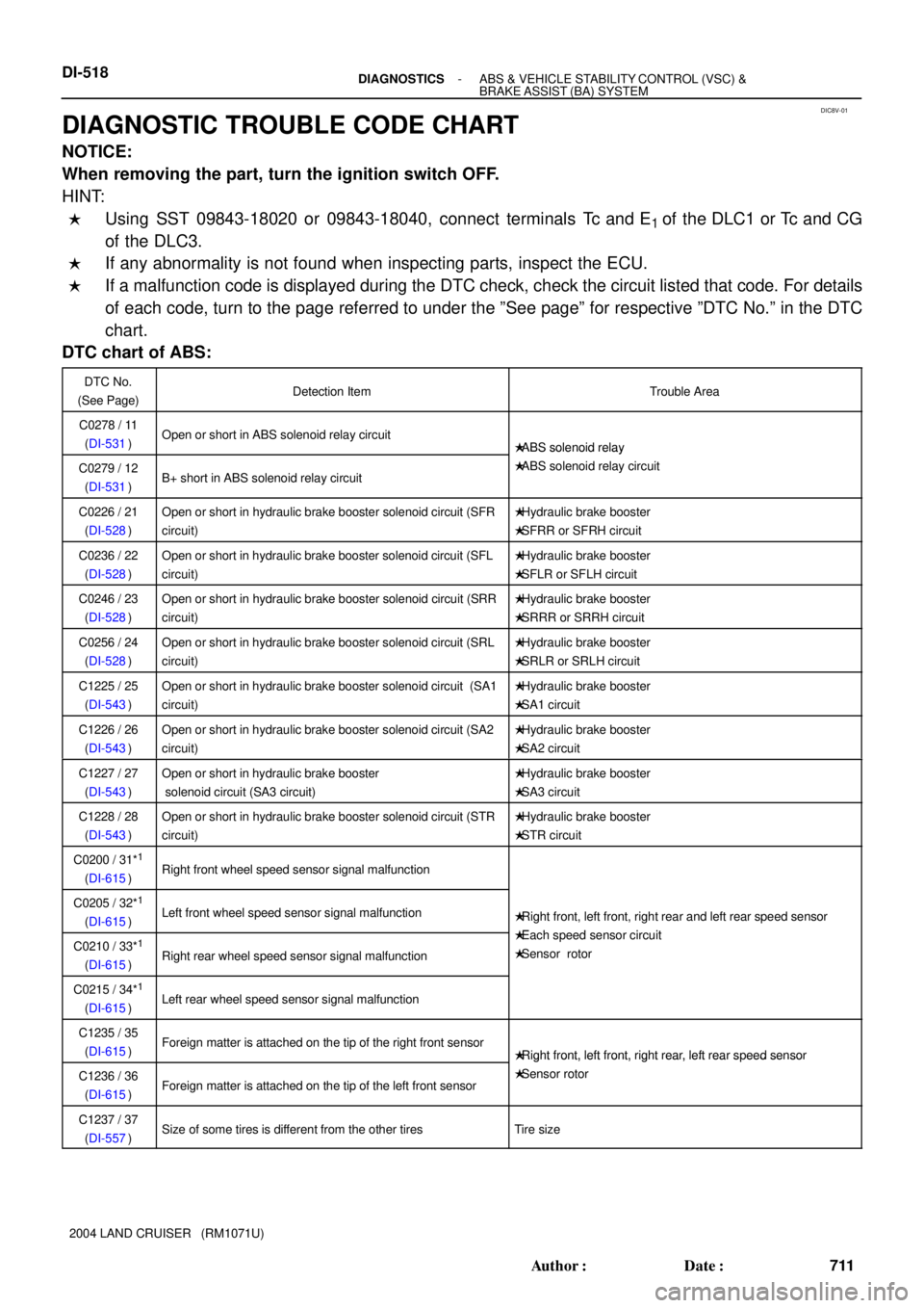
DIAGNOSTIC TROUBLE CODE CHART
NOTICE:
When removing the part, turn the ignition switch OFF.
HINT:
�Using SST 09843-18020 or 09843-18040, connect terminals Tc and E1 of the DLC1 or Tc and CG
of the DLC3.
�If any abnormality is not found when inspecting parts, inspect the ECU.
�If a malfunction code is displayed during the DTC check, check the circuit listed that code. For details
of each code, turn to the page referred to under the ºSee pageº for respective ºDTC No.º in the DTC
chart.
DTC chart of ABS:
DTC No.
(See Page)Detection ItemTrouble Area
C0278 / 11
(DI-531)Open or short in ABS solenoid relay circuit�ABS solenoid relay
C0279 / 12
(DI-531)B+ short in ABS solenoid relay circuit
�ABS solenoid relay
�ABS solenoid relay circuit
C0226 / 21
(DI-528)Open or short in hydraulic brake booster solenoid circuit (SFR
circuit)�Hydraulic brake booster
�SFRR or SFRH circuit
C0236 / 22
(DI-528)Open or short in hydraulic brake booster solenoid circuit (SFL
circuit)�Hydraulic brake booster
�SFLR or SFLH circuit
C0246 / 23
(DI-528)Open or short in hydraulic brake booster solenoid circuit (SRR
circuit)�Hydraulic brake booster
�SRRR or SRRH circuit
C0256 / 24
(DI-528)Open or short in hydraulic brake booster solenoid circuit (SRL
circuit)�Hydraulic brake booster
�SRLR or SRLH circuit
C1225 / 25
(DI-543)Open or short in hydraulic brake booster solenoid circuit (SA1
circuit)�Hydraulic brake booster
�SA1 circuit
C1226 / 26
(DI-543)Open or short in hydraulic brake booster solenoid circuit (SA2
circuit)�Hydraulic brake booster
�SA2 circuit
C1227 / 27
(DI-543)Open or short in hydraulic brake booster
solenoid circuit (SA3 circuit)�Hydraulic brake booster
�SA3 circuit
C1228 / 28
(DI-543)Open or short in hydraulic brake booster solenoid circuit (STR
circuit)�Hydraulic brake booster
�STR circuit
C0200 / 31*1
(DI-615)Right front wheel speed sensor signal malfunction
C0205 / 32*1
(DI-615)Left front wheel speed sensor signal malfunction�Right front, left front, right rear and left rear speed sensor
Eh d i itC0210 / 33*1
(DI-615)Right rear wheel speed sensor signal malfunction
�Each speed sensor circuit
�Sensor rotor
C0215 / 34*1
(DI-615)Left rear wheel speed sensor signal malfunction
C1235 / 35
(DI-615)Foreign matter is attached on the tip of the right front sensor�Right front, left front, right rear, left rear speed sensor
C1236 / 36
(DI-615)Foreign matter is attached on the tip of the left front sensor
�Right front, left front, right rear, left rear s eed sensor
�Sensor rotor
C1237 / 37
(DI-557)Size of some tires is different from the other tiresTire size
Page 900 of 3115

F17604
DIC8S-02
F02201N09214F05476
DLC1
E1
Tc
TcDLC3
CG
- DIAGNOSTICSABS & VEHICLE STABILITY CONTROL (VSC) &
BRAKE ASSIST (BA) SYSTEMDI-505
698 Author�: Date�:
2004 LAND CRUISER (RM1071U)
PRE-CHECK
1. DIAGNOSIS SYSTEM
(a) Check the warning lights and buzzer.
(1) Release the parking brake lever.
(2) When the ignition switch is turned ON, check that
the ABS, VSC TRAC and BRAKE warning lights,
VSC OFF, SLIP and TRAC indicator lights come on
for 3 sec.
(3) When depressing the brake pedal repeatedly, it
may turn on the ABS, VSC TRAC and BRAKE warn-
ing lights, VSC OFF indicator light and buzzer.
HINT:
�If the ECU stores DTC, the ABS, VSC TRAC and BRAKE
warning lights and VSC OFF indicator light come ON.
�If the indicator check result is not normal, proceed to trou-
bleshooting for the ABS warning light circuit, VSC TRAC
warning light circuit, brake warning light circuit, VSC OFF
indicator light circuit, SLIP indicator light circuit and AC-
TIVE TRAC indicator light circuit.
Trouble AreaSee Page
ABS warning light circuitDI-627
VSC TRAC warning light circuitDI-631
BRAKE warning light circuitDI-635
VSC OFF indicator light circuitDI-645
SLIP indicator light circuitDI-639
TRAC indicator light circuitDI-642
(b) In case of not using hand-held tester:
Check the DTC.
(1) Using SST, connect terminals Tc and E
1 of the
DLC1 or Tc and CG of the DLC3.
SST 09843-18020 or 09843-18040
(2) Turn the ignition switch ON.
(3) Read the DTC from the ABS or VSC TRAC warning
light on the combination meter.
HINT:
�If no code appears, inspect the Tc circuit, ABS or VSC
TRAC warning light circuit.
Trouble AreaSee page
Tc circuitDI-651
ABS warning light circuitDI-627
VSC TRAC warning light circuitDI-631
Page 901 of 3115

R01346
Normal Code
0.25 sec.
0.25 sec. 2 sec.
ON
OFF
ON
OFF0.5 sec. 0.5 sec.
Code 11 and 21
4 sec.1.5 sec.
2.5 sec.
Code 11 Code 21
F06425
Hand-held
Tester
DLC3
F05576
DI-506- DIAGNOSTICSABS & VEHICLE STABILITY CONTROL (VSC) &
BRAKE ASSIST (BA) SYSTEM
699 Author�: Date�:
2004 LAND CRUISER (RM1071U)
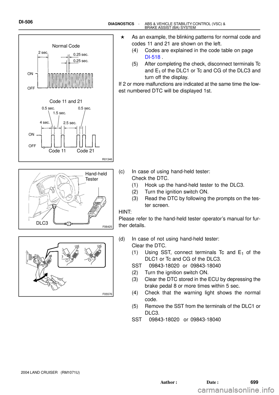
�As an example, the blinking patterns for normal code and
codes 11 and 21 are shown on the left.
(4) Codes are explained in the code table on page
DI-518.
(5) After completing the check, disconnect terminals Tc
and E
1 of the DLC1 or Tc and CG of the DLC3 and
turn off the display.
If 2 or more malfunctions are indicated at the same time the low-
est numbered DTC will be displayed 1st.
(c) In case of using hand-held tester:
Check the DTC.
(1) Hook up the hand-held tester to the DLC3.
(2) Turn the ignition switch ON.
(3) Read the DTC by following the prompts on the tes-
ter screen.
HINT:
Please refer to the hand-held tester operator's manual for fur-
ther details.
(d) In case of not using hand-held tester:
Clear the DTC.
(1) Using SST, connect terminals Tc and E
1 of the
DLC1 or Tc and CG of the DLC3.
SST 09843-18020 or 09843-18040
(2) Turn the ignition switch ON.
(3) Clear the DTC stored in the ECU by depressing the
brake pedal 8 or more times within 5 sec.
(4) Check that the warning light shows the normal
code.
(5) Remove the SST from the terminals of the DLC1 or
DLC3.
SST 09843-18020 or 09843-18040