Page 619 of 3115

INSTALLATION
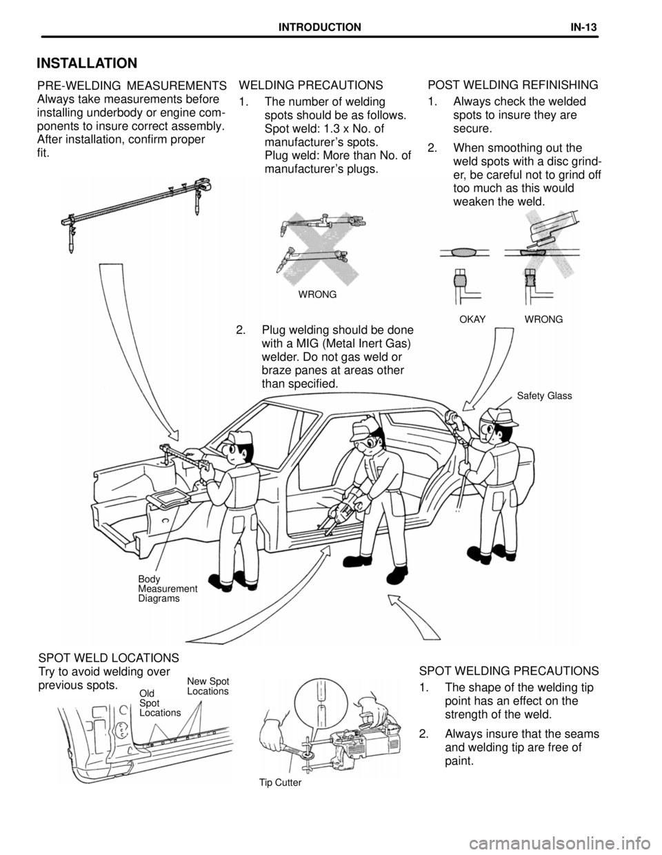
PRE-WELDING MEASUREMENTS
Always take measurements before
installing underbody or engine com-
ponents to insure correct assembly.
After installation, confirm proper
fit.WELDING PRECAUTIONS
1. The number of welding
spots should be as follows.
Spot weld: 1.3 x No. of
manufacturer's spots.
Plug weld: More than No. of
manufacturer's plugs.POST WELDING REFINISHING
1. Always check the welded
spots to insure they are
secure.
2. When smoothing out the
weld spots with a disc grind-
er, be careful not to grind off
too much as this would
weaken the weld.
WRONG
WRONG
OKAY
2. Plug welding should be done
with a MIG (Metal Inert Gas)
welder. Do not gas weld or
braze panes at areas other
than specified.
Safety Glass
Body
Measurement
Diagrams
SPOT WELDING PRECAUTIONS
1. The shape of the welding tip
point has an effect on the
strength of the weld.
2. Always insure that the seams
and welding tip are free of
paint. SPOT WELD LOCATIONS
Try to avoid welding over
previous spots.New Spot
Locations
Old
Spot
Locations
Tip Cutter
INTRODUCTIONIN-13
Page 627 of 3115

mm in.
150
2505.91
9.84
QUARTER PANEL (CUT)
Replacement Parts
QUARTER PANEL
HOW TO USE THIS MANUAL
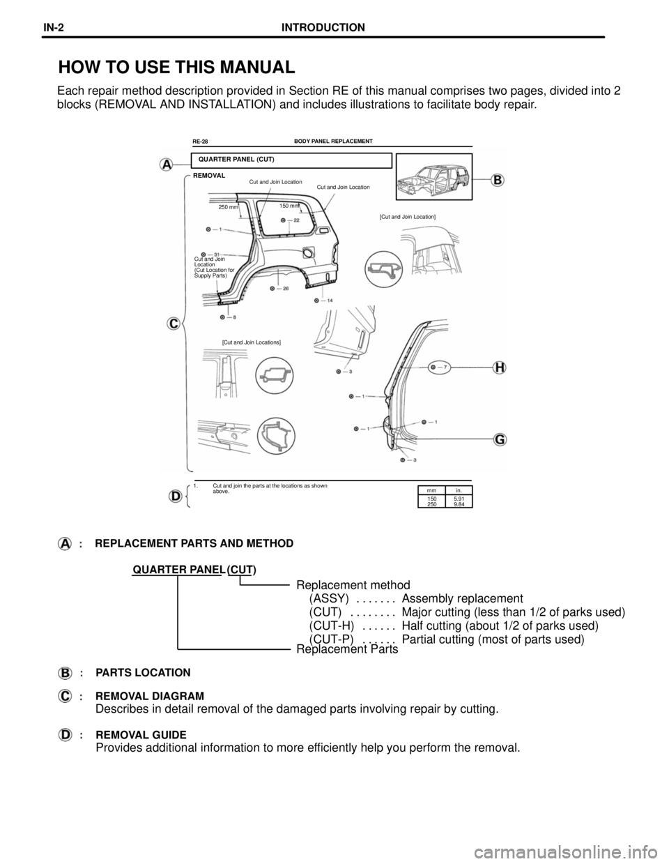
Each repair method description provided in Section RE of this manual comprises two pages, divided into 2
blocks (REMOVAL AND INSTALLATION) and includes illustrations to facilitate body repair.
BODY PANEL REPLACEMENT
RE-28
REMOVALCut and Join Location
Cut and Join Location
150 mm
250 mm
[Cut and Join Location]
Cut and Join
Location
(Cut Location for
Supply Parts)
[Cut and Join Locations]
1. Cut and join the parts at the locations as shown
above.
REPLACEMENT PARTS AND METHOD
(CUT)
Replacement method
(ASSY) Assembly replacement. . . . . . .
(CUT) Major cutting (less than 1/2 of parks used). . . . . . . .
(CUT-H) Half cutting (about 1/2 of parks used). . . . . .
(CUT-P) Partial cutting (most of parts used). . . . . .
PARTS LOCATION
REMOVAL DIAGRAM
Describes in detail removal of the damaged parts involving repair by cutting.
REMOVAL GUIDE
Provides additional information to more efficiently help you perform the removal.
INTRODUCTIONIN-2
Page 628 of 3115

mmin,
50.20RE-29 BODY PANEL REPLACEMENT
INSTALLATIONButt Weld
Butt Weld
Foamed Material
Application Areas
Body Sealer
Butt Weld
Body Sealer
about 5 mm
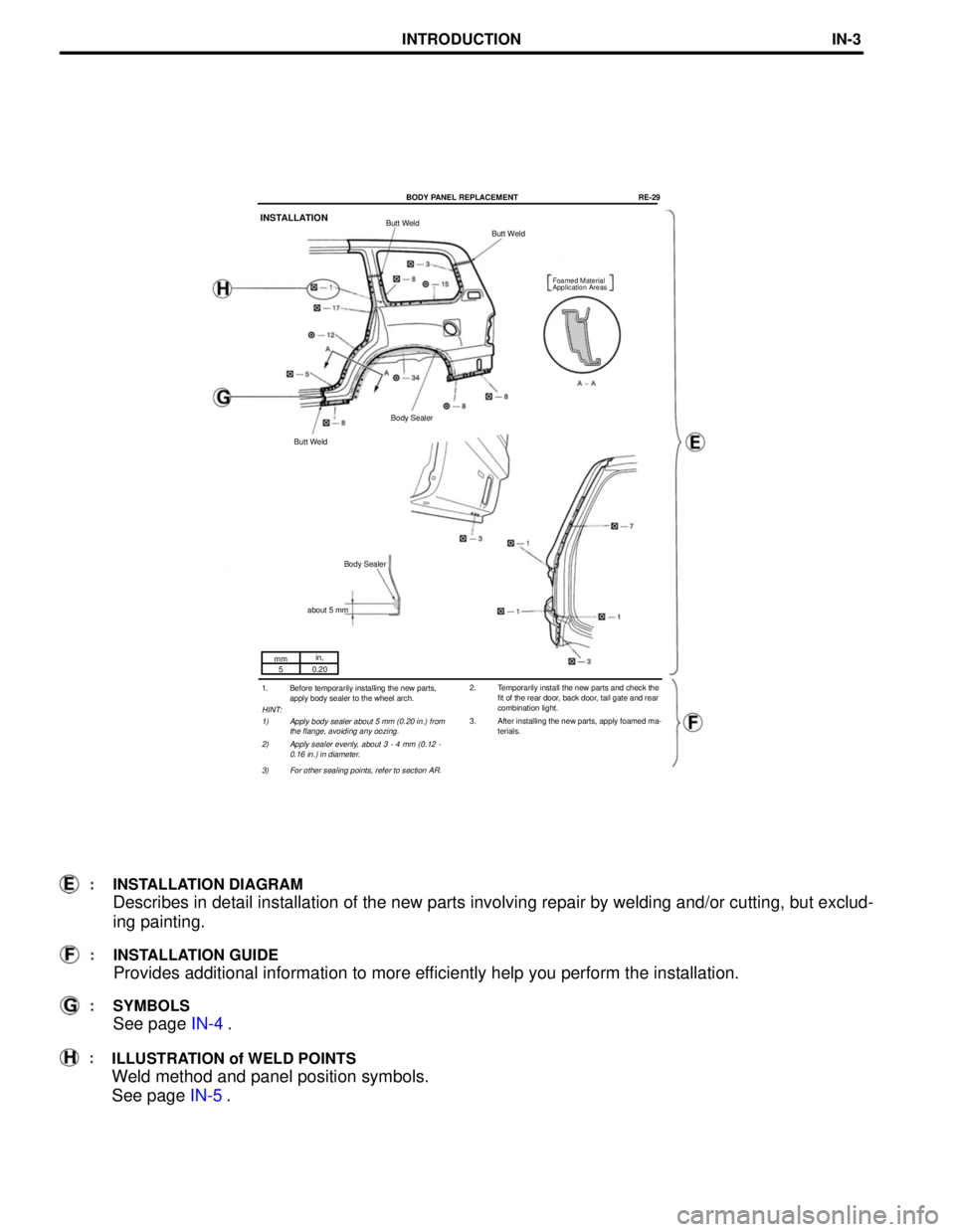
2. Temporarily install the new parts and check the
fit of the rear door, back door, tail gate and rear
combination light.
3. After installing the new parts, apply foamed ma-
terials. 1. Before temporarily installing the new parts,
apply body sealer to the wheel arch.
HINT:
1) Apply body sealer about 5 mm (0.20 in.) from
the flange, avoiding any oozing.
2) Apply sealer evenly, about 3 - 4 mm (0.12 -
0.16 in.) in diameter.
3) For other sealing points, refer to section AR.
INSTALLATION DIAGRAM
Describes in detail installation of the new parts involving repair by welding and/or cutting, but exclud-
ing painting.
INSTALLATION GUIDE
Provides additional information to more efficiently help you perform the installation.
SYMBOLS
See page IN-4.
ILLUSTRATION of WELD POINTS
Weld method and panel position symbols.
See page IN-5.
INTRODUCTIONIN-3
Page 636 of 3115
SYMBOLSMEANINGILLUSTRATION
SAW CUT OR
ROUGH CUT
REMOVE BRAZE
(See page IN-5) SPOT WELD OR
MIG PLUG WELD WELD POINTS
BRAZE CONTINUOUS MIG
WELD (BUTT WELD
OR TACK WELD)
BODY SEALER
SYMBOLS
The following symbols are used in the welding Diagrams in Section RE of this manual to indicate cutting
areas and the types of weld required.
INTRODUCTIONIN-4
Page 651 of 3115
INSTALLATION
Butt Weld
Pillar Reinforcement
Inner Pillar
Rocker Panel
Reinforcement
Butt Weld
Butt Weld
Foamed Material
Application Area
Butt Weld
Butt Weld
Butt Weld
1. Temporarily install the new parts and mea-
sure each part in accordance with the body
dimension diagram.
2. Temporarily install the new parts and check
the fit of the front door and rear door.3. After welding inner pillar and rocker panel
reinforcement and pillar reinforcement to the
vehicle install the outer pillar.
4. After installing the new parts, apply foamed
materials.
BODY PANEL REPLACEMENTRE-19
Page 660 of 3115
mm in.
20
0.79 Foamed Material
Application Area
Butt Weld
Butt Weld
Butt Weld
Butt Weld
Tack Weld (20 mm)
Butt Weld
6. Apply foamed material to the pillar section. 4. Temporarily install the new parts and measure
each part in accordance with the body dimen-
sion diagram.
5. Before welding the new parts, check the fit of
the front door, front fender and windshield
glass.
BODY PANEL REPLACEMENTRE-17
Page 662 of 3115
INSTALLATION
1. Temporarily install the new parts and measure
each part in accordance with the body dimen-
sion diagram.
BODY PANEL REPLACEMENTRE-7
Page 666 of 3115
INSTALLATION
1. Temporarily install the new parts and measure
each part in accordance with the body dimen-
sion diagram.2. Temporarily install the front fender and hood,
and check the fit.
BODY PANEL REPLACEMENTRE-13