Page 1376 of 3115
- DIAGNOSTICSENGINE
DI-327
520 Author�: Date�:
2004 LAND CRUISER (RM1071U)
5 Check if DTC output recur?
PREPARATION:
(a) Connect the hand-held tester to the DLC3.
(b) Disconnect the battery terminals or remove the EFI or ECD No. 1 fuse and ETCS fuse (Clear DTCs).
(c) Start the engine.
(d) Drive the engine at idle for 15 seconds or more.
CHECK:
Read the DTC output.
OK:
No DTC output.
OK System is OK.
NG
Replace ECM (See page SF-60).
Page 1379 of 3115
DI-330
- DIAGNOSTICSENGINE
523 Author�: Date�:
2004 LAND CRUISER (RM1071U)
4 Check if DTC output recur?
PREPARATION:
(a) Connect the OBD II scan tool to the DLC3.
(b) Disconnect the battery terminals or remove the EFI or ECD No. 1 fuse and ETCS fuse (Clear DTCs).
(c) Start the engine.
(d) Drive the engine at idle for 15 seconds or more.
CHECK:
Read the DTC output.
OK:
No DTC output.
OK System is OK.
NG
Replace ECM (See page SF-60).
Page 1385 of 3115

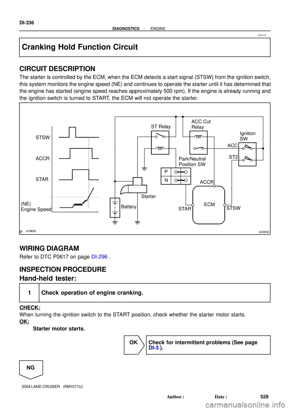
A19655A20059
STSW
ACCR
STAR
(NE)
Engine SpeedStarterPark/Neutral
Position SW
N P ST RelayACC Cut
Relay
Ignition
SW
ACC
ST2
ACCR
STSW
STAR BatteryECM
DI-336
- DIAGNOSTICSENGINE
529 Author�: Date�:
2004 LAND CRUISER (RM1071U)
Cranking Hold Function Circuit
CIRCUIT DESCRIPTION
The starter is controlled by the ECM, when the ECM detects a start signal (STSW) from the ignition switch,
this system monitors the engine speed (NE) and continues to operate the starter until it has determined that
the engine has started (engine speed reaches approximately 500 rpm). If the engine is already running and
the ignition switch is turned to START, the ECM will not operate the starter.
WIRING DIAGRAM
Refer to DTC P0617 on page DI-296.
INSPECTION PROCEDURE
Hand-held tester:
1 Check operation of engine cranking.
CHECK:
When turning the ignition switch to the START position, check whether the starter motor starts.
OK:
Starter motor starts.
OK Check for intermittent problems (See page
DI-3).
NG
DIC2U-01
Page 1394 of 3115

DI079-18
ENGINE CONTROL SYSTEM Check Sheet
Customer's Name
Driver's Name
Data Vehicle
Brought in
Engine model
VIN
Production Date
Licence Plate No.
Odometer Reading
Problem Symptoms
Engine does
not Start
Difficult to
Start
Poor Idling
Poor
Driveability
Engine Stall
Others
Engine does not crankNo initial combustionNo complete combustion
Engine cranks slowly
Other
Incorrect first idleIdling rpm is abnormalHigh ( rpm)Low ( rpm)
Rough idling
Other
HesitationBack fireMuffler explosion (after-fire)Surging
Knocking
Other
Soon after startingAfter accelerator pedal depressed
After accelerator pedal released
During A/C operation
Shifting from N to D
Other
Dates Problem
Occurred
Problem Frequency
Condition When
Problem Occurs
Weather
Engine Operation
Engine Temp. Place Outdoor
TemperatureConstant
Sometimes ( times per day/month)Once only
Other
Fine
CloudyRainySnowyVarious/Other
Hot
Warm CoolCold (approx. °C/ °F)
Highway
SuburbsInner cityUphillDownhill
Rough road
Other
Cold
Warming upAfter warming upAny temp.Other
Starting
Just after starting ( min.)IdlingRacing
Driving
Constant speedAccelerationDeceleration
A/C switch ON/OFF
Other
Condition of malfunction indicator lightRemains on Sometimes light up Does not light up
NormalMalfunction code(s) (code )
Freezed frame data ( )
NormalMalfunction code(s) (code )
Freezed frame data ( )
Normal Mode
(Pre-check)
Check Mode DTC InspectionInspector's
Name
km
miles
(MIL)
DI-2
- DIAGNOSTICSENGINE
195 Author�: Date�:
2004 LAND CRUISER (RM1071U)
CUSTOMER PROBLEM ANALYSIS CHECK
Page 1402 of 3115

- DIAGNOSTICSENGINE
DI-43
236 Author�: Date�:
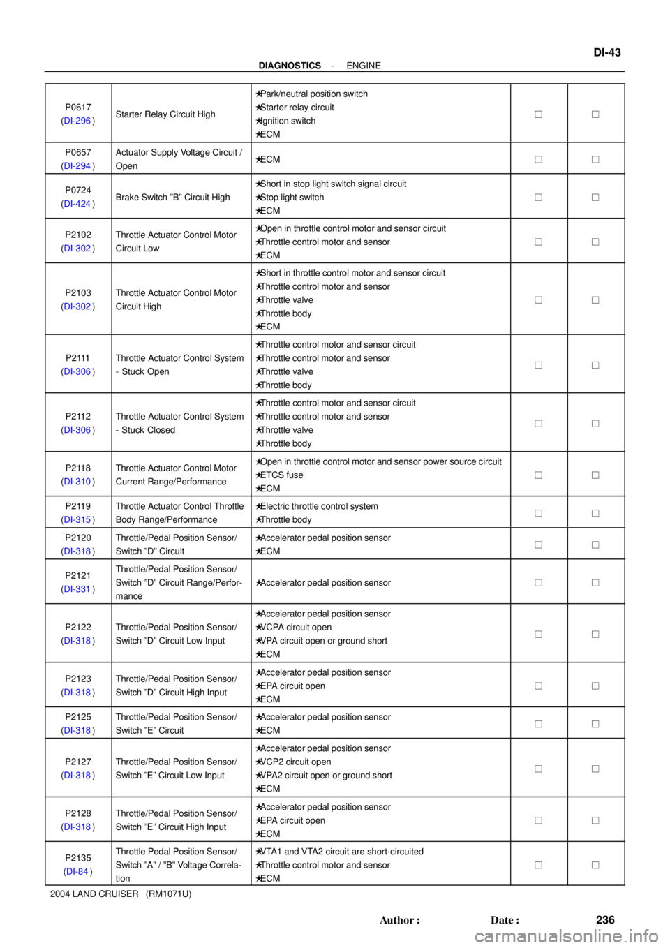
2004 LAND CRUISER (RM1071U)P0617
(DI-296)
Starter Relay Circuit High
�Park/neutral position switch
�Starter relay circuit
�Ignition switch
�ECM
��
P0657
(DI-294)Actuator Supply Voltage Circuit /
Open�ECM��
P0724
(DI-424)Brake Switch ºBº Circuit High
�Short in stop light switch signal circuit
�Stop light switch
�ECM
��
P2102
(DI-302)Throttle Actuator Control Motor
Circuit Low�Open in throttle control motor and sensor circuit
�Throttle control motor and sensor
�ECM
��
P2103
(DI-302)Throttle Actuator Control Motor
Circuit High
�Short in throttle control motor and sensor circuit
�Throttle control motor and sensor
�Throttle valve
�Throttle body
�ECM
��
P2111
(DI-306)Throttle Actuator Control System
- Stuck Open
�Throttle control motor and sensor circuit
�Throttle control motor and sensor
�Throttle valve
�Throttle body
��
P2112
(DI-306)Throttle Actuator Control System
- Stuck Closed
�Throttle control motor and sensor circuit
�Throttle control motor and sensor
�Throttle valve
�Throttle body
��
P2118
(DI-310)Throttle Actuator Control Motor
Current Range/Performance�Open in throttle control motor and sensor power source circuit
�ETCS fuse
�ECM
��
P2119
(DI-315)Throttle Actuator Control Throttle
Body Range/Performance�Electric throttle control system
�Throttle body��
P2120
(DI-318)Throttle/Pedal Position Sensor/
Switch ºDº Circuit�Accelerator pedal position sensor
�ECM��
P2121
(DI-331)Throttle/Pedal Position Sensor/
Switch ºDº Circuit Range/Perfor-
mance
�Accelerator pedal position sensor��
P2122
(DI-318)Throttle/Pedal Position Sensor/
Switch ºDº Circuit Low Input
�Accelerator pedal position sensor
�VCPA circuit open
�VPA circuit open or ground short
�ECM
��
P2123
(DI-318)Throttle/Pedal Position Sensor/
Switch ºDº Circuit High Input�Accelerator pedal position sensor
�EPA circuit open
�ECM
��
P2125
(DI-318)Throttle/Pedal Position Sensor/
Switch ºEº Circuit�Accelerator pedal position sensor
�ECM��
P2127
(DI-318)Throttle/Pedal Position Sensor/
Switch ºEº Circuit Low Input
�Accelerator pedal position sensor
�VCP2 circuit open
�VPA2 circuit open or ground short
�ECM
��
P2128
(DI-318)Throttle/Pedal Position Sensor/
Switch ºEº Circuit High Input�Accelerator pedal position sensor
�EPA circuit open
�ECM
��
P2135
(DI-84)Throttle Pedal Position Sensor/
Switch ºAº / ºBº Voltage Correla-
tion�VTA1 and VTA2 circuit are short-circuited
�Throttle control motor and sensor
�ECM
��
Page 1408 of 3115

A04550
12 345678
11 12 13 14 15 16 910
DLC3
- DIAGNOSTICSENGINE
DI-5
198 Author�: Date�:
(b) Check the DLC3.
The vehicle's ECM uses the ISO 9141-2 for communica-
tion protocol. The terminal arrangement of the DLC3 com-
plies with SAE J1962 and matches the ISO 9141-2 for-
mat.
SymbolNameResult
(Terminal No.)(Reference terminal)(Condition)
SILBus º+º linePulse generation
(7)(5 - Signal ground)(During transmission)
CGChassis ground1 W or less
(4)(Body ground)(Always)
SGSignal ground1 W or less
(5)(Body ground)(Always)
BATBattery positive9 to 14 V
(16)(Body ground)(Always)
HINT:
Connect the cable of the hand-held tester to the DLC3, turn the
ignition switch ON and attempt to use the hand-held tester. If
the screen displays UNABLE TO CONNECT TO VEHICLE, a
problem exists in the vehicle side or the tester side.
�If the communication is normal when the tool is connected
to another vehicle, inspect the DLC3 on the original ve-
hicle.
�If the communication is still impossible when the tool is
connected to another vehicle, the problem is probably in
the tool itself, so consult the Service Department listed in
the tool's instruction manual.
(c) Inspect the battery voltage.
Battery Voltage: 11 to 14 V
If voltage is below 11 V, recharge the battery before proceeding.
(d) Check the MIL.
(1) The MIL comes on when the ignition switch is turned
ON and the engine is not running.
HINT:
If the MIL is not illuminated, troubleshoot the MIL circuit (See
page DI-355).
(2) When the engine is started, the MIL should not illu-
minate. If the lamp remains on, the diagnosis sys-
tem has detected a malfunction or abnormality in
the system.
Page 1419 of 3115

DI-16
- DIAGNOSTICSENGINE
209 Author�: Date�:
FUEL SYS #1
Fuel system status (Bank1)/
OL or CL or OLDRIVE or OL-
FAULT or CLFAULT
Idli ft i CL
�OL: Open Loop-has not yet sa-
tisfied conditions to go closed
loop.
�CL: Closed Loop-using oxygen
sensor(s) as feed back for fuel
control.
�OL DRIVE: Open loop due to
dri ing conditions (Po er enrich
FUEL SYS #2
Fuel system status (Bank2)/
OL or CL or OLDRIVE or OL-
FAULT or CLFAULT
Idling after warming up: CLdriving conditions (Power enrich-
ment, deceleration enlargement).
�OL FAULT: Open loop due to de-
tected system fault.
�CL FAULT: Closed loop, but fault
with at least one oxygen sensor
may be using single oxygen sen-
sor for fuel control.
FC IDLIdle fuel cut/
ON or OFFFuel cut operation: ON
FC IDL = ºONº when throttle valve
fully closed and engine speed is
over 1,500 rpm.
MILMIL status/
ON or OFFMIL ON: ON-
STARTER SIGStarter signal/
ON or OFFCranking: ON-
A/C SIGA/C signal/
ON or OFFA/C ON: ON-
PNP SW [NSW]Park/neutral position switch signal/
ON or OFFP or N range: ON-
ELECT LOAD SIGElectrical load signal/
ON or OFFDefogger switch ON: ON-
STOP LIGHT SWStop light switch/
ON or OFF�Brake pedal depressed: ON
�Brake pedal released: OFF-
FUEL PMP SP CTLFuel pump speed control status/
ON or OFFIdling: ON-
FUEL PUMP/SPDFuel pump/speed status/
ON/H or OFF/M, LIdling: ON-
A/C MAG CLUTCHA/C magnet clutch status/
ON or OFFA/C magnet clutch ON: ON-
EVAP VSVVSV status for EVAP control/
ON or OFFVSV operating: ONVSV for EVAP is controlled by the
ECM (ground side duty control)
IGNITIONIgnition counter/
Min.: 0, Max.: 4000 to 400-
VAPOR PRESSVapor pressure/
Min.: -4.125 kPa, Max.: 2.125 kPaFuel tank cap removed:
0 kPaPressure inside of fuel tank as
read by the vapor pressure sen-
sor.
CYL #1 - CYL #8Misfire ratio of the cylinder/
Min.: 0%, Max.: 50%0%This item is displayed in only idling
*1: If no conditions are specifically stated for ºldlingº, it means the shift lever is in the N or P position, the A/C
switch is OFF and all accessory switches are OFF.
Page 1433 of 3115

DI1L9-13
DI-48
- DIAGNOSTICSENGINE
241 Author�: Date�:
2004 LAND CRUISER (RM1071U)
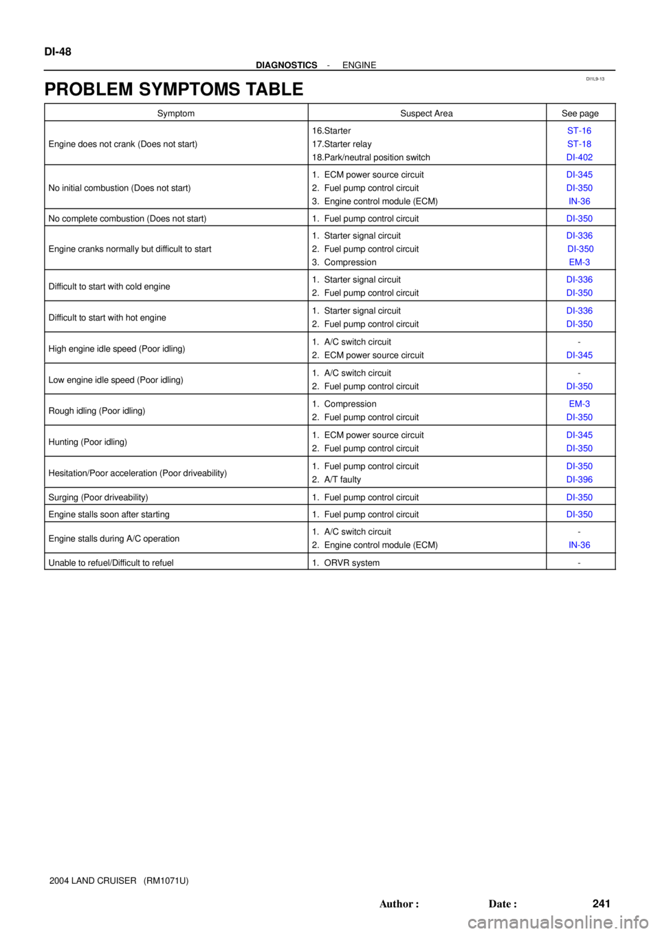
PROBLEM SYMPTOMS TABLE
SymptomSuspect AreaSee page
Engine does not crank (Does not start)
16.Starter
17.Starter relay
18.Park/neutral position switchST-16
ST-18
DI-402
No initial combustion (Does not start)
1. ECM power source circuit
2. Fuel pump control circuit
3. Engine control module (ECM)DI-345
DI-350
IN-36
No complete combustion (Does not start)1. Fuel pump control circuitDI-350
Engine cranks normally but difficult to start
1. Starter signal circuit
2. Fuel pump control circuit
3. CompressionDI-336
DI-350
EM-3
Difficult to start with cold engine1. Starter signal circuit
2. Fuel pump control circuitDI-336
DI-350
Difficult to start with hot engine1. Starter signal circuit
2. Fuel pump control circuitDI-336
DI-350
High engine idle speed (Poor idling)1. A/C switch circuit
2. ECM power source circuit-
DI-345
Low engine idle speed (Poor idling)1. A/C switch circuit
2. Fuel pump control circuit-
DI-350
Rough idling (Poor idling)1. Compression
2. Fuel pump control circuitEM-3
DI-350
Hunting (Poor idling)1. ECM power source circuit
2. Fuel pump control circuitDI-345
DI-350
Hesitation/Poor acceleration (Poor driveability)1. Fuel pump control circuit
2. A/T faultyDI-350
DI-396
Surging (Poor driveability)1. Fuel pump control circuitDI-350
Engine stalls soon after starting1. Fuel pump control circuitDI-350
Engine stalls during A/C operation1. A/C switch circuit
2. Engine control module (ECM)-
IN-36
Unable to refuel/Difficult to refuel1. ORVR system-