Page 2307 of 2389
STANDARD BOLT TORQUE SPECIFICATIONS
HOW TO DETERMINE BOLT STRENGTH
Hexagon flange
bolt w/ washer
hexagon bolt Hexagon flange
bolt w/ washer
hexagon bolt
Three
protruding
lines Tw o
protruding
lines
Tw o
protruding
lines
Four
protruding
lines Hexagon
head bolt
Hexagon
head bolt
Hexagon
head bolt Hexagon
head bolt
Welded bolt Stud bolt
No mark
Grooved
No mark
No mark
Class
Class
MarkMark
± STANDARD BOLT TORQUE SPECIFICATIONSB±2Torque Specifications
Page 2308 of 2389
SPECIFIED TORQUE FOR STANDARD BOLTS
Hexagon flange bolt
Hexagon head boltSpecified torque
Diameter
mmPitch
. mm Class
± STANDARD BOLT TORQUE SPECIFICATIONSTorque SpecificationsB±3
Page 2323 of 2389

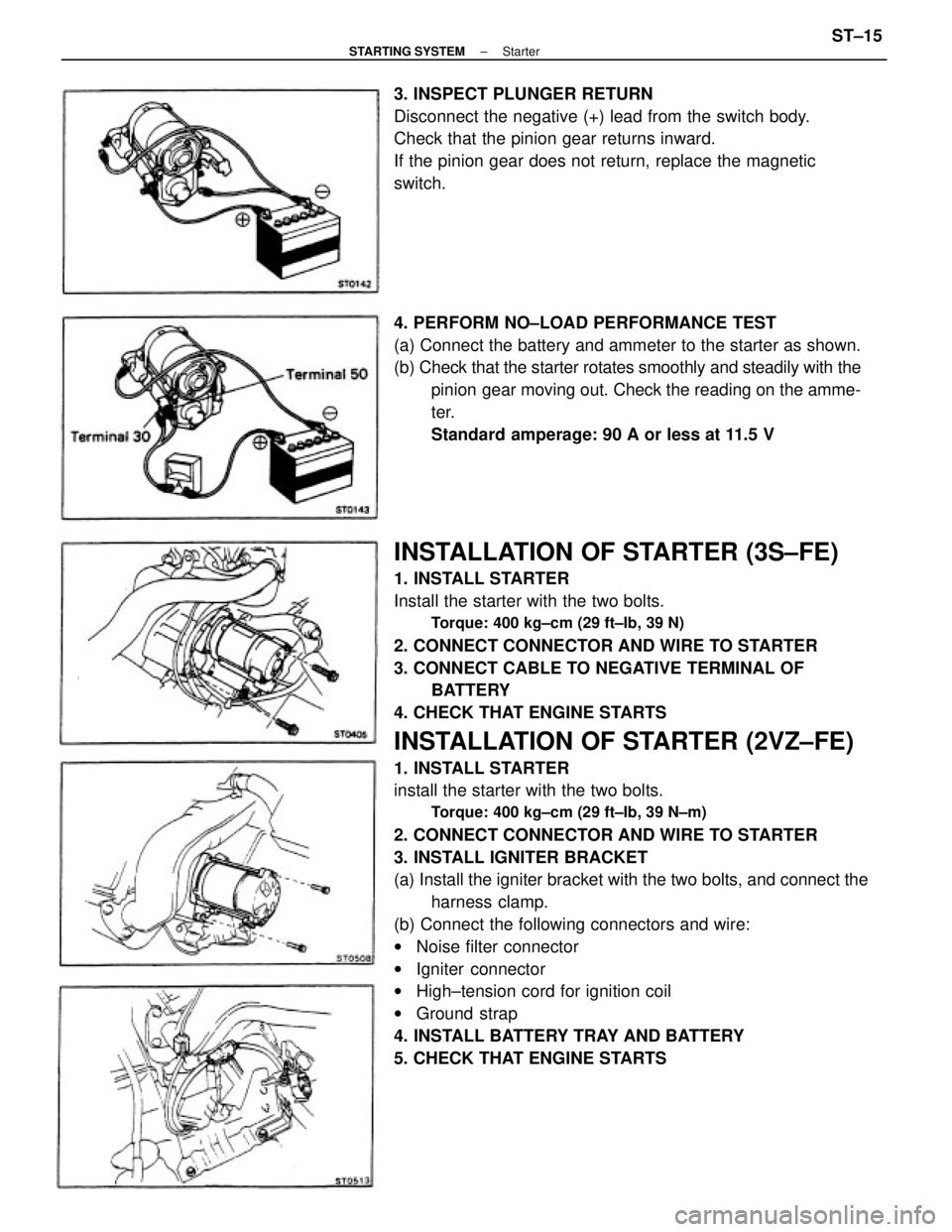
INSTALLATION OF STARTER (3S±FE)
1. INSTALL STARTER
Install the starter with the two bolts.
Torque: 400 kg±cm (29 ft±Ib, 39 N)
2. CONNECT CONNECTOR AND WIRE TO STARTER
3. CONNECT CABLE TO NEGATIVE TERMINAL OF
BATTERY
4. CHECK THAT ENGINE STARTS
INSTALLATION OF STARTER (2VZ±FE)
1. INSTALL STARTER
install the starter with the two bolts.
Torque: 400 kg±cm (29 ft±Ib, 39 N±m)
2. CONNECT CONNECTOR AND WIRE TO STARTER
3. INSTALL IGNITER BRACKET
(a) Install the igniter bracket with the two bolts, and connect the
harness clamp.
(b) Connect the following connectors and wire:
wNoise filter connector
wIgniter connector
wHigh±tension cord for ignition coil
wGround strap
4. INSTALL BATTERY TRAY AND BATTERY
5. CHECK THAT ENGINE STARTS 4. PERFORM NO±LOAD PERFORMANCE TEST
(a) Connect the battery and ammeter to the starter as shown.
(b) Check that the starter rotates smoothly and steadily with the
pinion gear moving out. Check the reading on the amme-
ter.
Standard amperage: 90 A or less at 11.5 V 3. INSPECT PLUNGER RETURN
Disconnect the negative (+) lead from the switch body.
Check that the pinion gear returns inward.
If the pinion gear does not return, replace the magnetic
switch.
± STARTING SYSTEMStarterST±15
Page 2334 of 2389
2. INSTALL MAIN SHAFT TO COLUMN TUBE
(a) Using snap ring pliers, install the snap ring in the low-
er groove of the main shaft.
(b) Apply molybdenum disulphide lithium base grease
to the thrust stopper.
(c) Insert the main shaft into the column tube.
3. INSTALL UPPER BRACKET TO COLUMN TUBE
(a) Install the upper bracket with the two tapered±head
bolts.
(b) Tighten the tapered±head bolts until the bolt heads
break off.
ASSEMBLY OF STEERING COLUMN
(See page SR±5)
1. INSTALL THRUST STOPPER
(a) Install a new O±ring to the thrust stopper.
(b) Install the thrust stopper and snap ring.
(e) Install the two thrust stopper set bolts.
Torque: 130 kg±cm (9 ft±11b, 13 N±m)(d) Using snap ring pliers, install the snap ring.
± STEERINGSteering Column (Non±Tilt Steering Column)SR±8
Page 2344 of 2389
ASSEMBLY OF STEERING COLUMN
(See page SR±9)
1. COAT ALL RUBBING PARTS WITH MOLYBDENUM
DISULPHIDE LITHIUM BASE GREASE
2. INSTALL THRUST STOPPER
(a) Install a new O±ring to the thrust stopper.
(b) Install the thrust stopper and snap ring with snap
ring pliers.
3. INSTALL UPPER TUBE
(a) Install the upper tube with the three bolts and cord
guide.
(b) Torque the two bolts.
Torque: 185 k9±cm (13 ft±Ib, 18 N±m)
(c) Tighten the tapered±head bolt until the bolt head
breaks off.
4. INSTALL ADJUSTING MEMORY COVER
Install the adjusting memory cover to the ratchet of the
column upper bracket.
6. SELECT COLLAR NO.1
Select a collar No. 1 which will eliminate all play. 5. INSTALL TILT ADJUST LEVER AND CONTROL LE-
VER
Outer diametermm(in.)
± STEERINGSteering Column (Tilt Steering Column)SR±14
Page 2345 of 2389
10. INSTALL TILT LEVER RETAINER
(a) Insert the serration bolt.
(b) Install the tilt lever retainer with the collar, cushion
and bolt.
Torque: 195 kg±cm (14 ft±Ib, 19 N±m)
(c) Install the two washers and two nuts.
Torque: 195 kg±cm (14 ft±Ib, 19 N±m)
7. INSTALL COLLAR NO. 1
8. INSTALL UPPER BRACKET TO BREAKAWAY
BRACKET
9. INSTALL TILT PAWL
(a) Pull up the control lever.
(b) Install the collar and tilt pawl to the set bolt.
(c) Install the spacer and release pin.
13. INSTALL COLLAR NO.2 AND SHIM
(a) Install the collar No.2 and shim.
(b) Install the bolt, washer and nut.
Torque: 195 kg±cm 114 ft±Ib, 19 N±m)
12. SELECT SHIM
Select one or two shims which fit snugly when pressed in
by hand. 11. SELECT COLLAR NO.2
Select a collar No±2 which will eliminate all play.
Thickness mm (in.) Outer diameter
mm(in.)
Mark
± STEERINGSteering Column ('Tilt Steering Column)SR±15
Page 2346 of 2389
17. INSTALL TENSION SPRINGS AND CORDS
(a) Fully tilt the main shaft upward.
(b) Connect the spring and cord, and hook the spring to
the hanger.
(c) Using a screwdriver, hook the cord end to the column
upper bracket. 14. INSTALL STOPPER6OLT
(a) Install the cushion to the stopper bolt.
(b) Install the stopper bolt, column cover support and
nut.
Torque: 110 kg±cm (8 ft±lb, 11 N±m)
16. INSTALL MAIN SHAFT
(a) Place the ignition key at the ACC position.
(b) Install the collar and spring to the main shaft and in-
sert the main shaft into the upper bracket.
(c) Using a screwdriver, push the main shaft to the main
shaft end.
(d) Using snap ring pliers, install the snap ring. 15. INSTALL TWO TENSION SPRINGS
± STEERINGSteering Column (Tilt Steering Column)SR±16
Page 2347 of 2389

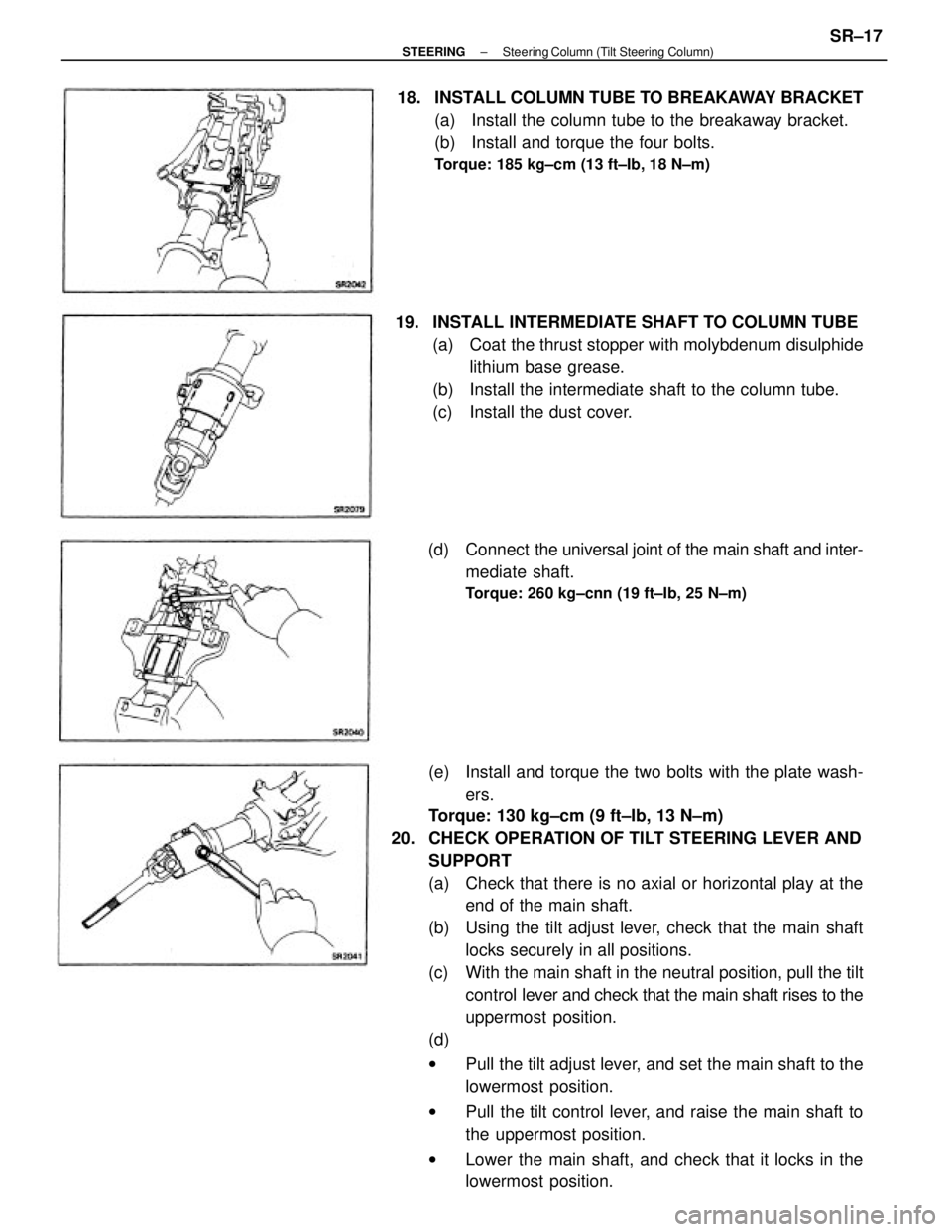
(e) Install and torque the two bolts with the plate wash-
ers.
Torque: 130 kg±cm (9 ft±Ib, 13 N±m)
20. CHECK OPERATION OF TILT STEERING LEVER AND
SUPPORT
(a) Check that there is no axial or horizontal play at the
end of the main shaft.
(b) Using the tilt adjust lever, check that the main shaft
locks securely in all positions.
(c) With the main shaft in the neutral position, pull the tilt
control lever and check that the main shaft rises to the
uppermost position.
(d)
wPull the tilt adjust lever, and set the main shaft to the
lowermost position.
wPull the tilt control lever, and raise the main shaft to
the uppermost position.
wLower the main shaft, and check that it locks in the
lowermost position. 19. INSTALL INTERMEDIATE SHAFT TO COLUMN TUBE
(a) Coat the thrust stopper with molybdenum disulphide
lithium base grease.
(b) Install the intermediate shaft to the column tube.
(c) Install the dust cover. 18. INSTALL COLUMN TUBE TO BREAKAWAY BRACKET
(a) Install the column tube to the breakaway bracket.
(b) Install and torque the four bolts.
Torque: 185 kg±cm (13 ft±Ib, 18 N±m)
(d) Connect the universal joint of the main shaft and inter-
mediate shaft.
Torque: 260 kg±cnn (19 ft±Ib, 25 N±m)
± STEERINGSteering Column (Tilt Steering Column)SR±17