Page 714 of 2389

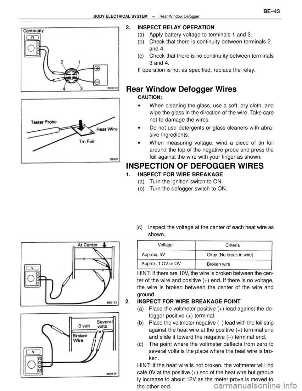
6. INSTALL REAR PILLAR UPPER GARNISH
(a) Install the clips to the garnish and tap the garnish onto
the body.
(b) Install the screw and screw cap.
7. INSTALL REAR SEAT BELT ANCHOR BOLT
Torque: 440 kg±cm (32 ft±Ib, 43 N±m)
8. INSTALL QUARTER INSIDE UPPER TRIM
9. INSTALL SEAT SIDE BACK
10. INSTALL QUARTER BELT MOULDING
11. INSTALL QUARTER WINDOW UPPER
MOULDING
12. INSTALL REAR ROOF DRIP MOULDING
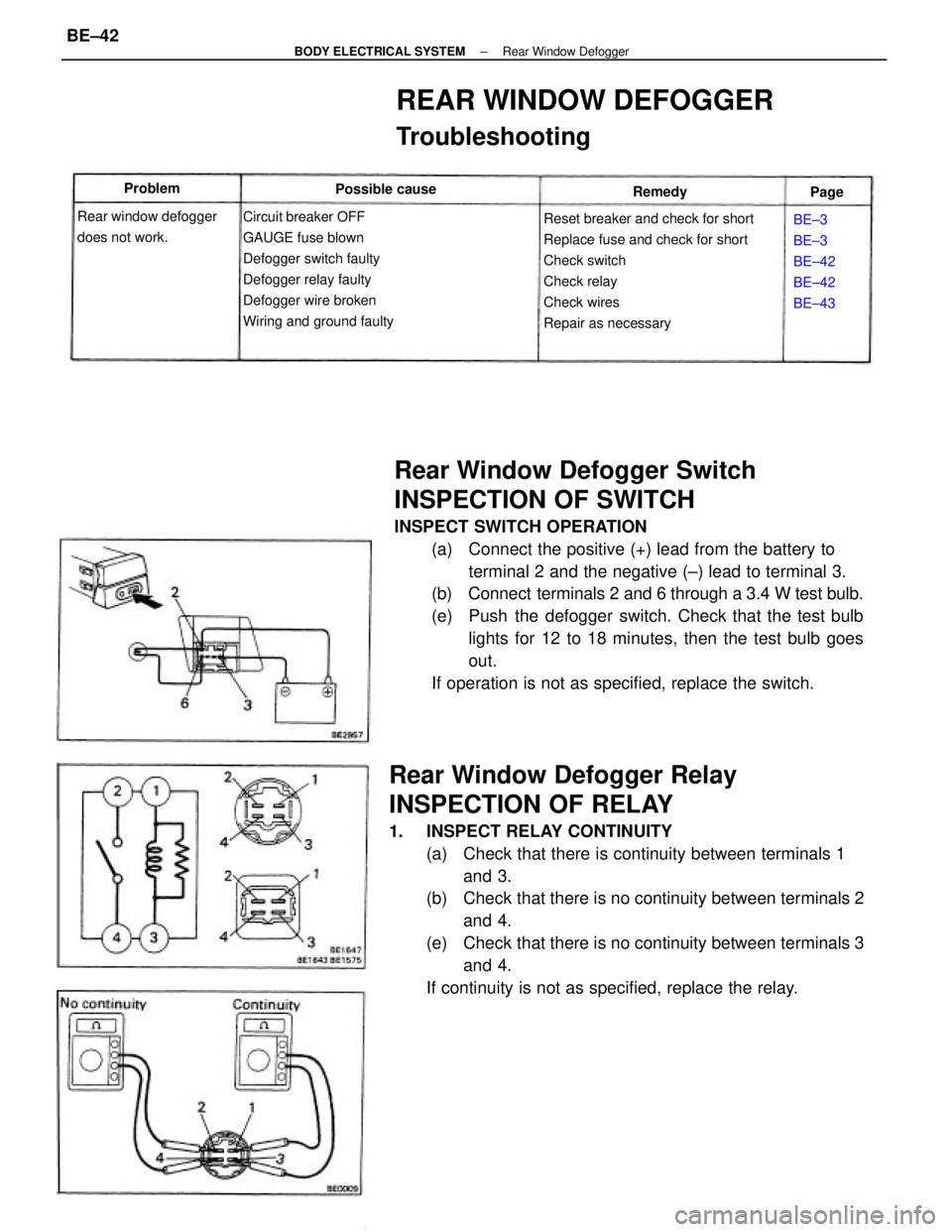
(See page BO±28) 4. INSTALL QUARTER WINDOW GLASS WITH FRONT
MOULDING
(a) Install the glass to the body.
(b) Install the eight window glass set nuts.
5. INSTALL QUARTER WINDOW REAR MOULDING
Install the rear moulding with two nuts. 2. COAT CONTACT SURFACE OF GLASS WITH PRIMER
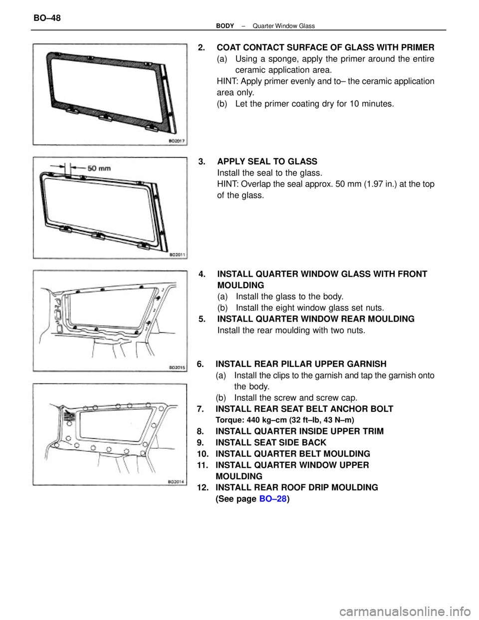
(a) Using a sponge, apply the primer around the entire
ceramic application area.
HINT: Apply primer evenly and to± the ceramic application
area only.
(b) Let the primer coating dry for 10 minutes.
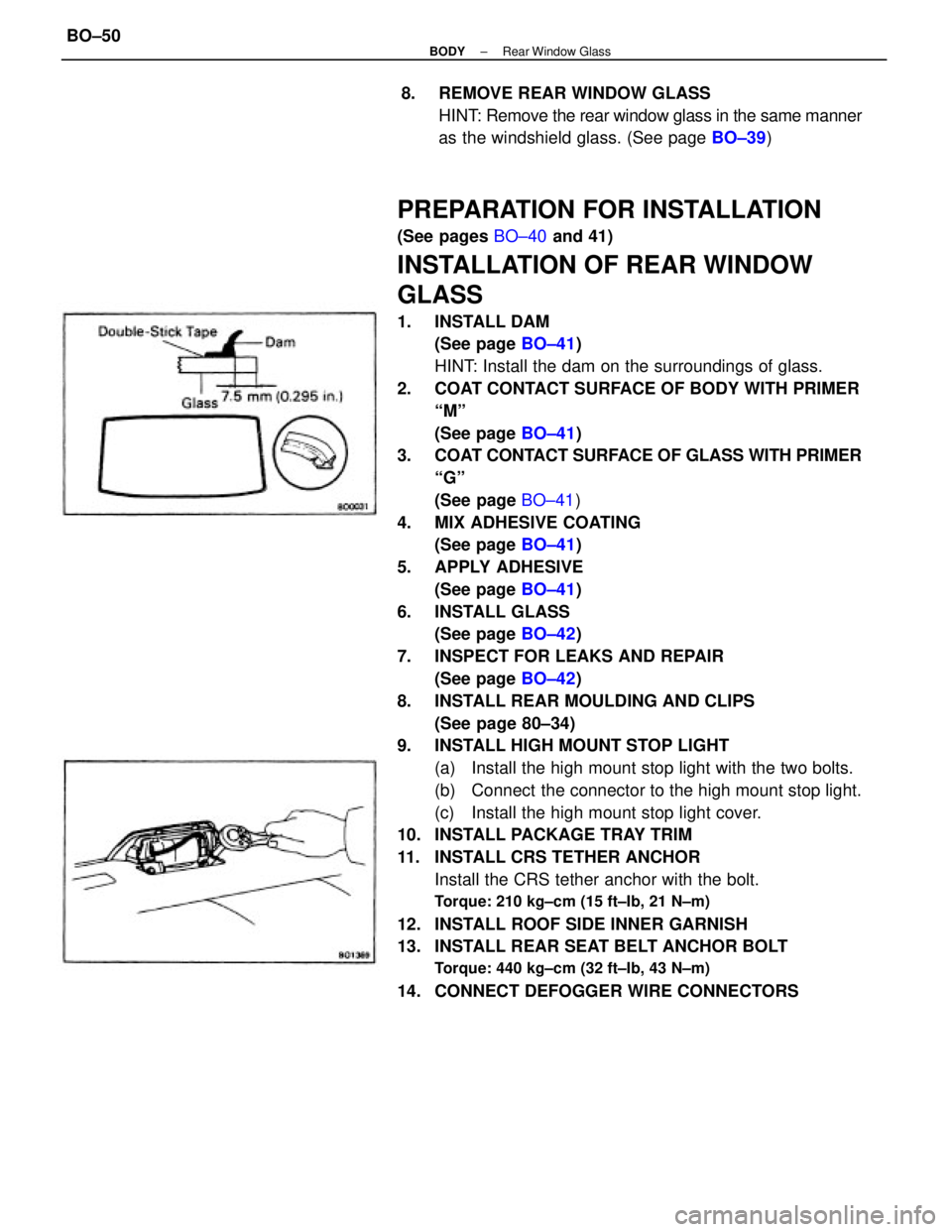
3. APPLY SEAL TO GLASS
Install the seal to the glass.
HINT: Overlap the seal approx. 50 mm (1.97 in.) at the top
of the glass.
± BODYQuarter Window GlassBO±48
Page 715 of 2389
REMOVAL OF REAR WINDOW GLASS
1. DISCONNECT DEFOGGER WIRE CONNECTORS
2. REMOVE REAR SEAT BELT ANCHOR BOLT
3. REMOVE ROOF SIDE INNER GARNISH
(See page BO±44)
4. REMOVE REAR MOULDING AND CLIPS
(See page BO±33)
5. REMOVE HIGH MOUNT STOP LIGHT
(a) Remove the high mount stop light cover.
(b) Disconnect the connector from the high mount stop
light.
(c) Remove the two bolts and high mount stop light.
6. REMOVE CRS TETHER ANCHOR
Remove the bolt with CRS tether anchor.
7. REMOVE PACKAGE TRAY TRIM
REAR WINDOW GLASS
PREPARE ITEMS LISTED
(See page BO±37)
COMPONENTS
± BODYRear Window GlassBO±49
Page 716 of 2389

PREPARATION FOR INSTALLATION
(See pages BO±40 and 41)
INSTALLATION OF REAR WINDOW
GLASS
1. INSTALL DAM
(See page BO±41)
HINT: Install the dam on the surroundings of glass.
2. COAT CONTACT SURFACE OF BODY WITH PRIMER
ªMº
(See page BO±41)
3. COAT CONTACT SURFACE OF GLASS WITH PRIMER
ªGº
(See page BO±41)
4. MIX ADHESIVE COATING
(See page BO±41)
5. APPLY ADHESIVE
(See page BO±41)
6. INSTALL GLASS
(See page BO±42)
7. INSPECT FOR LEAKS AND REPAIR
(See page BO±42)
8. INSTALL REAR MOULDING AND CLIPS
(See page 80±34)
9. INSTALL HIGH MOUNT STOP LIGHT
(a) Install the high mount stop light with the two bolts.
(b) Connect the connector to the high mount stop light.
(c) Install the high mount stop light cover.
10. INSTALL PACKAGE TRAY TRIM
11. INSTALL CRS TETHER ANCHOR
Install the CRS tether anchor with the bolt.
Torque: 210 kg±cm (15 ft±Ib, 21 N±m)
12. INSTALL ROOF SIDE INNER GARNISH
13. INSTALL REAR SEAT BELT ANCHOR BOLT
Torque: 440 kg±cm (32 ft±Ib, 43 N±m)
14. CONNECT DEFOGGER WIRE CONNECTORS8. REMOVE REAR WINDOW GLASS
HINT: Remove the rear window glass in the same manner
as the windshield glass. (See page BO±39)
± BODYRear Window GlassBO±50
Page 745 of 2389
LUGGAGE COMPARTMENT (SEDAN)
Rear floor pan bumper front installation hole ± front Back window upper frame standard hole ± rear
Upper back reinforcement center mark Rear sprin support front holeNomenclatureHole d¿a.
Symbol
± BODYBody DimensionsBO±79
Page 788 of 2389

Rear Window Defogger Switch
INSPECTION OF SWITCH
INSPECT SWITCH OPERATION
(a) Connect the positive (+) lead from the battery to
terminal 2 and the negative (±) lead to terminal 3.
(b) Connect terminals 2 and 6 through a 3.4 W test bulb.
(e) Push the defogger switch. Check that the test bulb
lights for 12 to 18 minutes, then the test bulb goes
out.
If operation is not as specified, replace the switch.
Rear Window Defogger Relay
INSPECTION OF RELAY
1. INSPECT RELAY CONTINUITY
(a) Check that there is continuity between terminals 1
and 3.
(b) Check that there is no continuity between terminals 2
and 4.
(e) Check that there is no continuity between terminals 3
and 4.
If continuity is not as specified, replace the relay.
Reset breaker and check for short
Replace fuse and check for short
Check switch
Check relay
Check wires
Repair as necessary
REAR WINDOW DEFOGGER
Troubleshooting
Circuit breaker OFF
GAUGE fuse blown
Defogger switch faulty
Defogger relay faulty
Defogger wire broken
Wiring and ground faulty Rear window defogger
does not work.BE±3
BE±3
BE±42
BE±42
BE±43 Possible cause Problem
Remedy
Page
± BODY ELECTRICAL SYSTEMRear Window DefoggerBE±42
Page 789 of 2389

Rear Window Defogger Wires
CAUTION:
wWhen cleaning the glass, use a soft, dry cloth, and
wipe the glass in the direction of the wire. Take care
not to damage the wires.
wDo not use detergents or glass cleaners with abra-
sive ingredients.
wWhen measuring voltage, wind a piece of tin foil
around the top of the negative probe and press the
foil against the wire with your finger as shown.
INSPECTION OF DEFOGGER WIRES
1. INSPECT FOR WIRE BREAKAGE
(a) Turn the ignition switch to ON.
(b) Turn the defogger switch to ON.
HINT: If there are 10V, the wire is broken between the cen-
ter of the wire and positive (+) end. If there is no voltage,
the wire is broken between the center of the wire and
ground.
2. INSPECT FOR WIRE BREAKAGE POINT
(a) Place the voltmeter positive (+) lead against the de-
fogger positive (+) terminal.
(b) Place the voltmeter negative (±) lead with the foil strip
against the heat wire at the positive (+) terminal end
and slide it toward the negative (±) terminal end.
(c) The point where the voltmeter deflects from zero to
several volts is the place where the heat wire is bro-
ken.
HINT: If the heat wire is not broken, the voltmeter will ind
cafe 0V at the positive (+) end of the heat wire but gradua
ly increase to about 12V as the meter prove is moved to
the other end. 2. INSPECT RELAY OPERATION
(a) Apply battery voltage to terminals 1 and 3.
(b) Check that there is continuity between terminals 2
and 4.
(c) Check that there is no continu,ity between terminals
3 and 4.
If operation is not as specified, replace the relay.
(c) Inspect the voltage at the center of each heat wire as
shown.
Okay (No break in wire)
Approx. 1 OV or OVApprrox. 5V
Broken wire Voltage
Criteria
± BODY ELECTRICAL SYSTEMRear Window DefoggerBE±43
Page 790 of 2389
3. REPAIR DEFOGGER WIRES
(a) Thoroughly mix the repair agent (Dupont paste No.
4817).
(b) Using a fine tip brush, apply a small amount to the
wire.
(c) After a few minutes, remove the masking tape.
(d) Allow the repair to stand at least 24 hours.
REPAIR OF DEFOGGER WIRES
1. CLEAN BROKEN WIRE TIPS WITH WHITE GASOLINE
2. PLACE MASKING TAPE ALONG BOTH SIDES OF
WIRE TO BE REPAIRED
± BODY ELECTRICAL SYSTEMRear Window DefoggerBE±44
Page 801 of 2389
Power Window Motor
INSPECTION OF MOTOR
1. INSPECT CIRCUIT BREAKER OPERATION
(a) With the window in the full closed position, hold the
power window switch in ºUPº position and check that
there is a circuit breaker operation noise within 4 to 40
seconds.
POWER WINDOW
Power Window Switch
INSPECTION OF SWITCH
INSPECT SWITCH CONTINUITY
Inspect the switch continuity between terminals.
If continuity is not as specified, replace the switch.Door switch: Front door
Door switch: Rear door
Operation windowSwitch position
Switch position
Window unlock
Switch
position
Switch
positionWindow lock
Ex. Front±left
Front±RightIllumination
Rear±Right
Front±left
Terminal
Front± Left
Terminal Terminal
TerminalRear±Left
DOWN
DOWN OFFOFF
± BODY ELECTRICAL SYSTEMPower WindowBE±55