Page 1052 of 2389
4. INSTALL FUEL TANK
When installing the fuel tank, refer to FI±65 for the installation
position of the cushion and the tightening torque.
5. CONNECT CABLE TO NEGATIVE TERMINAL OF
BATTERY 2. INSTALL FUEL PUMP TO FUEL PUMP BRACKET
(a) Connect the fuel hose to the outlet port of the fuel pump.
(b) Connect the wires to the fuel pump with the two nuts.
(e) Push the lower side of the fuel pump, and install the fuel
pump.
3. INSTALL FUEL PUMP BRACKET TO FUEL TANK
(a) Install a new gasket and the pump bracket with the seven
screws.
Torque: 40 kg±cm (35 in.±lb, 3.9 N±m)
(b) Install the bolt of the bracket.
INSTALLATION OF FUEL PUMP
(See page FI±74)
1. INSTALL FUEL PUMP FILTER TO FUEL PUMP
(a) Install the pump filter with a new clip.
(b) Install the rubber cushion.5. REMOVE FUEL PUMP FILTER FROM FUEL PUMP
(a) Remove the rubber cushion.
(b) Using a small screwdriver, remove the clip.
(c) Pull out the pump filter.
± EFI SYSTEMFuel System (Fuel Pump)_FI±75
Page 1053 of 2389
REMOVAL OF FUEL PUMP
CAUTION: Do not smoke or work near an open flame when
working the fuel pump.
1. DISCONNECT CABLE FROM NEGATIVE TERMINAL
OF BATTERY
2. REMOVE FUEL TANK
4. REMOVE FUEL PUMP±FROM FUEL PUMP BRACKET
(a) Pull off the lower side of the fuel pump from the bracket.
(b) Remove the two nuts, and disconnect the wires from the fuel
pump.
(c) Disconnect the fuel hose from the fuel pump. 3. REMOVE FUEL PUMP BRACKET FROM FUEL TANK
Remove the seven bolts, pull out the pump bracket.
COMPONENTS (4WD)
± EFI SYSTEMFuel System (Fuel Pump)FI±76
Page 1054 of 2389
2. INSTALL FUEL PUMP TO FUEL PUMP BRACKET
(a) Connect the fuel hose to the outlet port of the fuel pump.
(b) Connect the wires to the fuel pump with the two nuts.
(c) Push the lower side of the fuel pump, and install the fuel
pump.
4. INSTALL FUEL TANK
When installing the fuel tank, refer to FI±65 for the installation
position of the cushion and the tightening torque.
5. CONNECT CABLE TO NEGATIVE TERMINAL OF
BATTERY INSTALLATION OF FUEL PUMP
(See page FI±76)
1. INSTALL FUEL PUMP FILTER TO FUEL PUMP
(a) Install the pump filter with a new clip.
(b) Install the rubber cushion.
3. INSTALL FUEL PUMP BRACKET TO FUEL TANK
Install a new gasket and the pump bracket with the seven
bolts.
Torque: 30 kg±cm (26 in.±lb, 2.9 N±m)
5. REMOVE FUEL PUMP FILTER FROM FUEL PUMP
(a) Remove the rubber cushion.
(b) Using a small screwdriver, remove the clip.
(e) Pull out the pump filter.
± EFI SYSTEMFuel System (Fuel Pump)FI±77
Page 1183 of 2389

No fuel supply to injector
wNo fuel in tank
wFuel pump no working
wFuel filter clogged
wFuel line clogged or leaking
EFI system problems
Ignition problems
wIgnition coil
wIgniter
wDistributor
Spark plug faulty
High±tension cord disconnected or broken
Vacuum leaks
wPCV line
wEGR line
wIntake manifold
wAir intake chamber
wThrottle body
wISC valve
wBrake booster tine
Pulling in air between air flow meter and
throttle body
Low compression
Spark plug faulty
High±tension cord faulty
Ignition problems
wIgnition coil
wIgniter
wDistributor
Incorrect ignition timing
Vacuum leaks
wPCV line
wEGR line
wIntake manifold
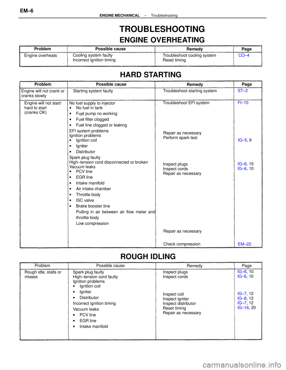
TROUBLESHOOTING
ENGINE OVERHEATING
Inspect coil
Inspect igniter
Inspect distributor
Reset timing
Repair as necessaryInspect plugs
Inspect cords
Repair as necessary Troubleshoot cooling system
Reset timing
Engine will not start/
hard to start
(cranks OK)Cooling system faulty
Incorrect ignition timing
Repair as necessary
Perform spark test Engine will not crank or
cranks slowly
IG±7, 12
IG±8, 12
IG±7, 12
IG±16, 20 Rough idle, stalls or
misses
HARD STARTING
Troubleshoot starting system
Inspect plugs
Inspect cords Troubleshoot EFI system
ROUGH IDLING
Starting system faulty
Check compression Repair as necessary Engine overheats
IG±6, 10
IG±6, 10 IG±6, 10
IG±6, 10 Possible cause
Possible cause Possible cause
Remedy Remedy
Problem
Remedy Problem Problem
IG±5, 9
EM±22Page
Page
Page CO±4
FI±10 ST±2
± ENGINE MECHANICALTroubleshootingEM±6
Page 1286 of 2389

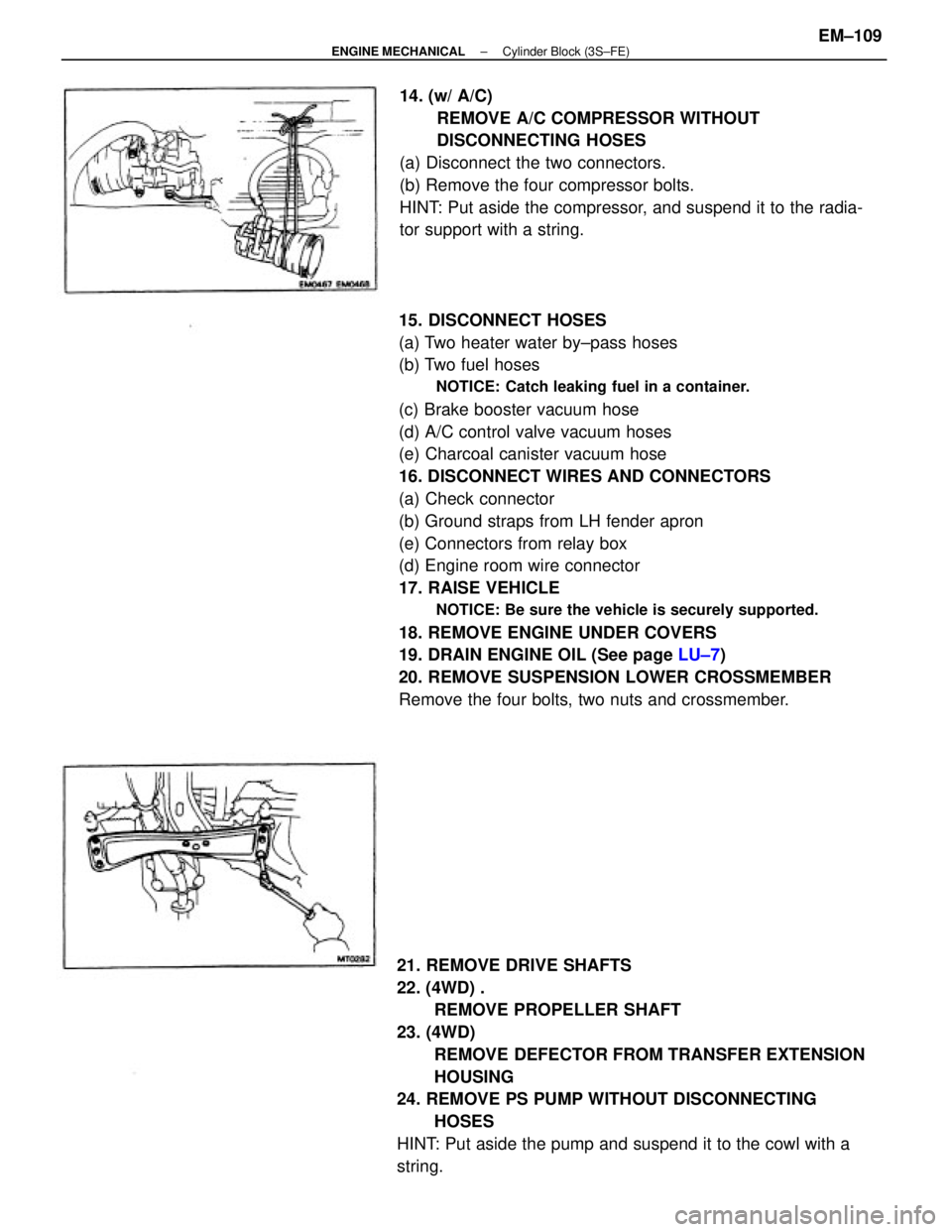
15. DISCONNECT HOSES
(a) Two heater water by±pass hoses
(b) Two fuel hoses
NOTICE: Catch leaking fuel in a container.
(c) Brake booster vacuum hose
(d) A/C control valve vacuum hoses
(e) Charcoal canister vacuum hose
16. DISCONNECT WIRES AND CONNECTORS
(a) Check connector
(b) Ground straps from LH fender apron
(e) Connectors from relay box
(d) Engine room wire connector
17. RAISE VEHICLE
NOTICE: Be sure the vehicle is securely supported.
18. REMOVE ENGINE UNDER COVERS
19. DRAIN ENGINE OIL (See page LU±7)
20. REMOVE SUSPENSION LOWER CROSSMEMBER
Remove the four bolts, two nuts and crossmember.
21. REMOVE DRIVE SHAFTS
22. (4WD) .
REMOVE PROPELLER SHAFT
23. (4WD)
REMOVE DEFECTOR FROM TRANSFER EXTENSION
HOUSING
24. REMOVE PS PUMP WITHOUT DISCONNECTING
HOSES
HINT: Put aside the pump and suspend it to the cowl with a
string.14. (w/ A/C)
REMOVE A/C COMPRESSOR WITHOUT
DISCONNECTING HOSES
(a) Disconnect the two connectors.
(b) Remove the four compressor bolts.
HINT: Put aside the compressor, and suspend it to the radia-
tor support with a string.
± ENGINE MECHANICALCylinder Block (3S±FE)EM±109
Page 1313 of 2389

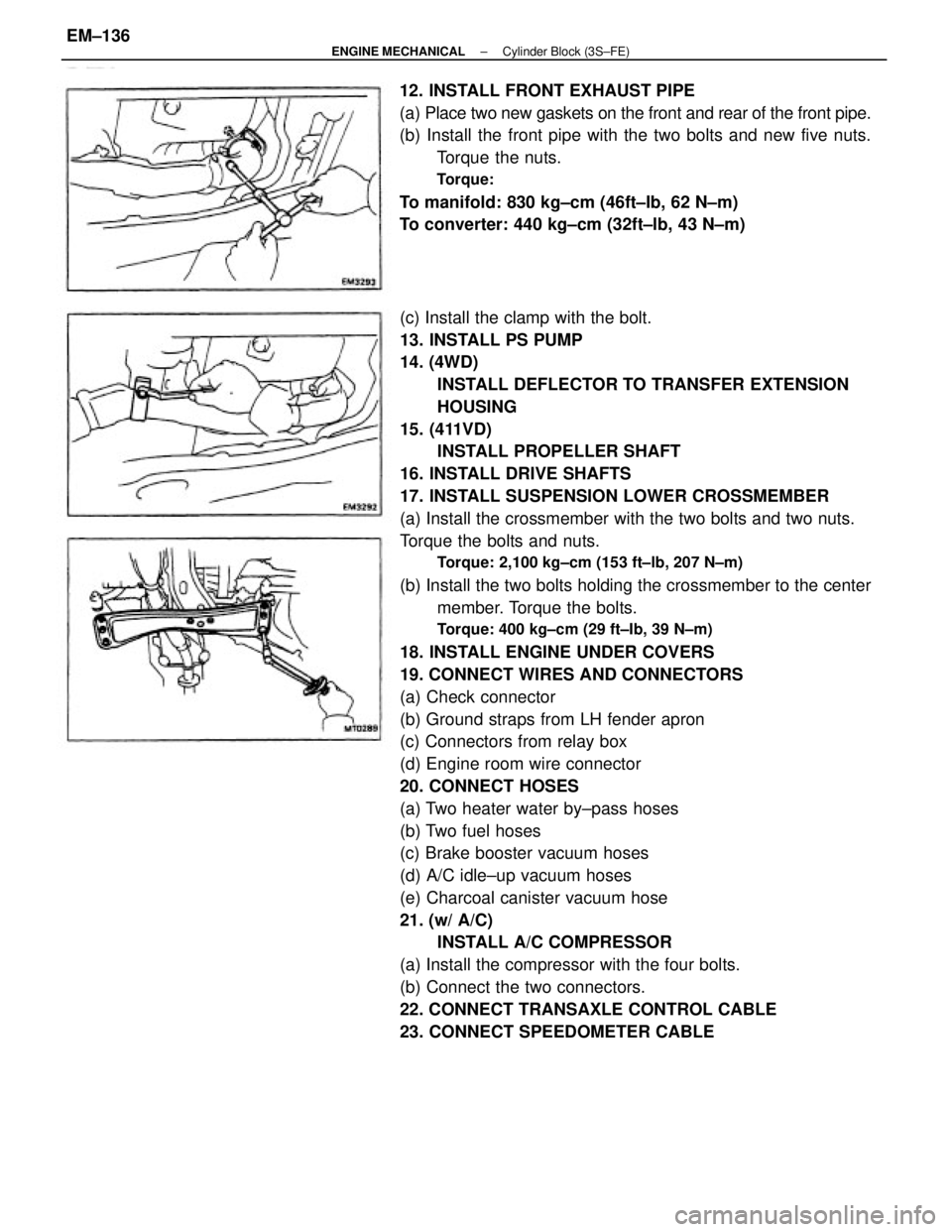
(c) Install the clamp with the bolt.
13. INSTALL PS PUMP
14. (4WD)
INSTALL DEFLECTOR TO TRANSFER EXTENSION
HOUSING
15. (411VD)
INSTALL PROPELLER SHAFT
16. INSTALL DRIVE SHAFTS
17. INSTALL SUSPENSION LOWER CROSSMEMBER
(a) Install the crossmember with the two bolts and two nuts.
Torque the bolts and nuts.
Torque: 2,100 kg±cm (153 ft±lb, 207 N±m)
(b) Install the two bolts holding the crossmember to the center
member. Torque the bolts.
Torque: 400 kg±cm (29 ft±Ib, 39 N±m)
18. INSTALL ENGINE UNDER COVERS
19. CONNECT WIRES AND CONNECTORS
(a) Check connector
(b) Ground straps from LH fender apron
(c) Connectors from relay box
(d) Engine room wire connector
20. CONNECT HOSES
(a) Two heater water by±pass hoses
(b) Two fuel hoses
(c) Brake booster vacuum hoses
(d) A/C idle±up vacuum hoses
(e) Charcoal canister vacuum hose
21. (w/ A/C)
INSTALL A/C COMPRESSOR
(a) Install the compressor with the four bolts.
(b) Connect the two connectors.
22. CONNECT TRANSAXLE CONTROL CABLE
23. CONNECT SPEEDOMETER CABLE 12. INSTALL FRONT EXHAUST PIPE
(a) Place two new gaskets on the front and rear of the front pipe.
(b) Install the front pipe with the two bolts and new five nuts.
Torque the nuts.
Torque:
To manifold: 830 kg±cm (46ft±Ib, 62 N±m)
To converter: 440 kg±cm (32ft±lb, 43 N±m)
± ENGINE MECHANICALCylinder Block (3S±FE)EM±136
Page 1318 of 2389

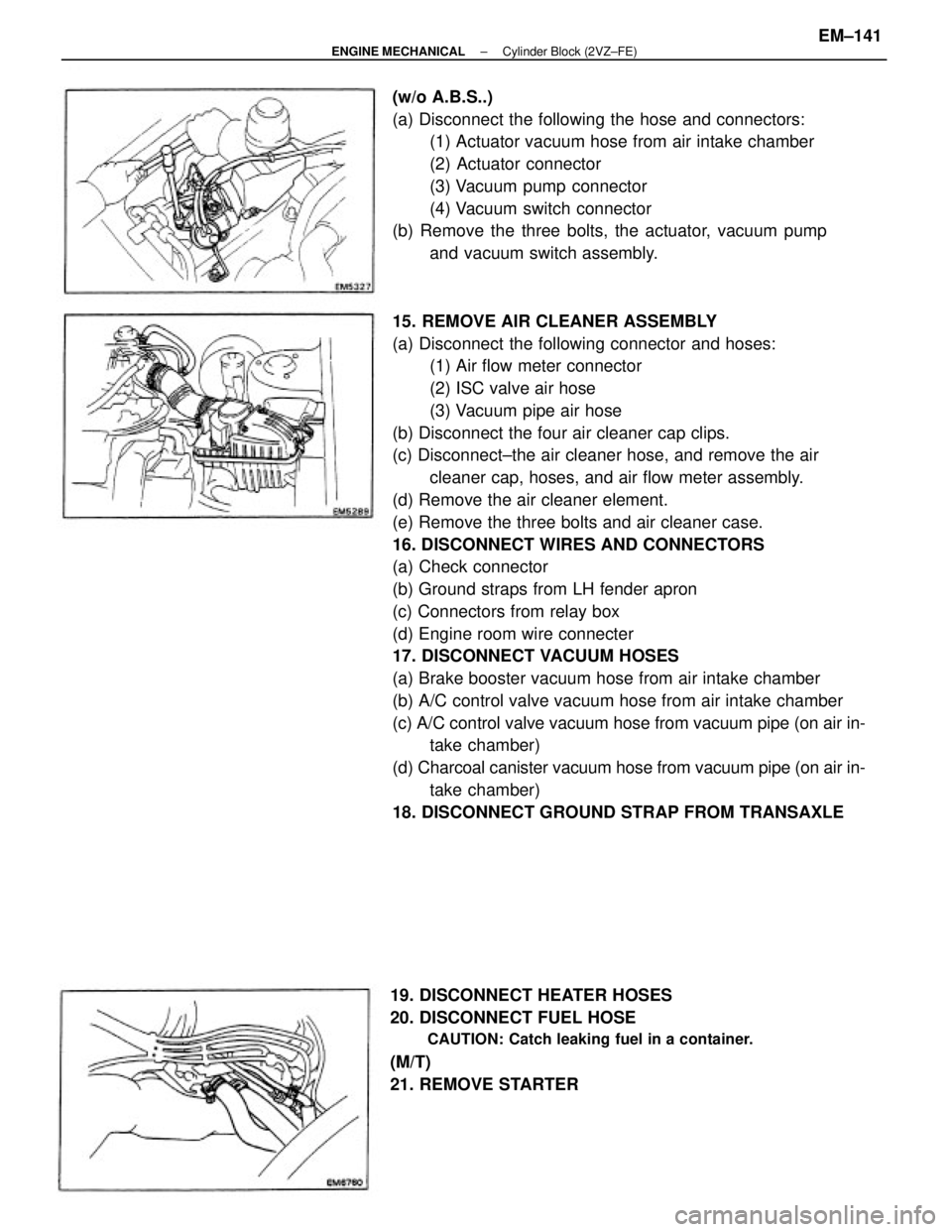
15. REMOVE AIR CLEANER ASSEMBLY
(a) Disconnect the following connector and hoses:
(1) Air flow meter connector
(2) ISC valve air hose
(3) Vacuum pipe air hose
(b) Disconnect the four air cleaner cap clips.
(c) Disconnect±the air cleaner hose, and remove the air
cleaner cap, hoses, and air flow meter assembly.
(d) Remove the air cleaner element.
(e) Remove the three bolts and air cleaner case.
16. DISCONNECT WIRES AND CONNECTORS
(a) Check connector
(b) Ground straps from LH fender apron
(c) Connectors from relay box
(d) Engine room wire connecter
17. DISCONNECT VACUUM HOSES
(a) Brake booster vacuum hose from air intake chamber
(b) A/C control valve vacuum hose from air intake chamber
(c) A/C control valve vacuum hose from vacuum pipe (on air in-
take chamber)
(d) Charcoal canister vacuum hose from vacuum pipe (on air in-
take chamber)
18. DISCONNECT GROUND STRAP FROM TRANSAXLE (w/o A.B.S..)
(a) Disconnect the following the hose and connectors:
(1) Actuator vacuum hose from air intake chamber
(2) Actuator connector
(3) Vacuum pump connector
(4) Vacuum switch connector
(b) Remove the three bolts, the actuator, vacuum pump
and vacuum switch assembly.
19. DISCONNECT HEATER HOSES
20. DISCONNECT FUEL HOSE
CAUTION: Catch leaking fuel in a container.
(M/T)
21. REMOVE STARTER
± ENGINE MECHANICALCylinder Block (2VZ±FE)EM±141
Page 2224 of 2389
Fuel tank band x Body
Cold start injector x Air intake chamber
Cold start injector pipe x Cold start injector
Cold start injector pipe x Delivery pipe
Fuel pressure regulator X Delivery pipe
Fuel return pipe x Fuel pressure regulator
Delivery pipe x Cylinder head
Throttle body x Air intake chamberFuel evaporation vent tube x Fuel tank 4WD
Fuel inlet pipe x Fuel tankFuel sender gauge
Fuel pump X Fuel tank
Specifications (Cont'd)
Torque Specifications
Coolant temp. 805C (1765F) Intake air temp. 205C (685F) Measuring plate fully closed
Measuring plate fully openThrottle valve fully closed
Throttle valve fully closedThrottle valve fully closedThrottle valve fully closed
Throttle valve fully openThrottle valve fully open
* 1 w/o ECT *2 w/ ECT Throttle valve openThrottle valve open
Part tightened ECU (cont'd) Resistance
Condition
Fuel line
± SERVICE SPECIFICATIONSEFI System (3S±FE)A±13