Page 894 of 2389
DISASSEMBLY OF PARKING BRAKE
1. REMOVE REAR DISC BRAKE ASSEMBLY
(a) Remove the axle carrier mounting bolt and nut of up-
per side.
(b) Remove the two mounting bolts and remove the disc
brake assembly.
(c) Suspend the disc brake so the hose is not stretched.
4. REMOVE FRONT SHOE, ADJUSTER AND TENSION
SPRING
(a) Slide out the front shoe and remove the shoe adjust-
er.
(b) Remove the shoe strut with spring.
(c) Disconnect the tension spring and remove the front
shoe. 3. REMOVE SHOE RETURN SPRINGS
[2WD (w/o A.B.S.) and 4WD]
Using SST, remove the shoe return springs.
SST 09717±20010 2. REMOVE ROTOR DISC
HINT: If the rotor disc cannot be removed easily, return the
shoe adjuster until the wheel turns freely.
[2WD (w/ A.B.S.)]
Using needle±nose pliers, remove the shoe return springs.
± BRAKE SYSTEMRear BrakeBR±43
Page 983 of 2389
2. REMOVE CLUTCH COVER AND DISC
(a) Place rnatchmarks on the flywheel and clutch cover.
(b) Loosen each set bolt one turn at a time until spring ten-
sion is released. ±
(c) Remove the set bolts, and pull off the clutch cover with
the clutch disc.
NOTICE: Do not drop the clutch disc.
REMOVAL OF CLUTCH UNIT
1. REMOVE TRANSAXLE FROM ENGINE
CLUTCH UNIT
COMPONENTS
E56F5 Transaxle (SV series/4WD) S51 Transaxle (SV series/2WD)
E52 Transaxle 1VZV series)
See pageTransaxle
MT±116MT±45MT±4
± CLUTCHClutch UnitCL±9
Page 985 of 2389

INSTALLATION OF CLUTCH UNIT
(See page CL±8)
1. INSTALL CLUTCH DISC AND COVER ON FLYWHEEL
(a) Insert SST in the clutch disc, and then set them and the cover
in position.
SST S51 Transaxle
09301±32010
E52, E56F5 Transaxle
09301±17010
(b) Align the matchmarks on the clutch cover and flywheel.
(e) Torque the bolts on the clutch cover in the order shown.
Torque: 195 kg±cm (14 ft±Ib, 19 N±m)
HINT: Temporarily tighten the No.1 and No.2 bolts. 5. INSPECT RELEASE BEARING
Turn the bearing by hand while applying force in the axial
direction.
HINT: The bearing is permanently lubricated and requires
no cleaning or lubrication.
If a problem is found, replace the bearing together with the
hub.
2. CHECK DIAPHRAGM SPRING TIP ALIGNMENT
Using a dial indicator with roller instrument, check the
diaphragm spring tip alignment.
Maximum non±alignment: 0.5 mm (0.020 in.)
If alignment is not as specified, using SST, adjust the
diaphragm spring tip alignment.
SST 09333±00013
3. APPLY MOLYBDENUM DISULPHIDE LITHIUM BASE
GREASE(NLGI N0.2) TO FOLLOWING PARTS:
(a) Release fork and hub contact points.
(b) Release fork and push rod contact point.
(e) Release fork pivot point.
± CLUTCHClutch UnitCL±11
Page 1200 of 2389
REMOVAL OF TIMING BELT
1. DISCONNECT CABLE FROM NEGATIVE TERMINAL
OF BATTERY
2. REMOVE RN FRONT WHEEL
3. REMOVE ENGINE RH UNDER COVER
4. REMOVE CRUISE CONTROL ACTUATOR
(See step 9 on page EM±108)
5. REMOVE DRIVE BELTS
6. REMOVE ALTERNATOR (See page CH±6)
7. REMOVE ALTERNATOR BRACKET
8. REMOVE RH MOUNTING STAY
(2WD)
Remove the three bolts and mounting stay.
TIMING BELT (3S±FE)
COMPONENTS
± ENGINE MECHANICALTiming Belt (3S±FE)EM±23
Page 1210 of 2389

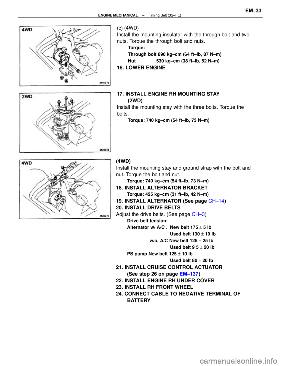
(4WD)
Install the mounting stay and ground strap with the bolt and
nut. Torque the bolt and nut.
Torque: 740 kg±cm (54 ft±Ib, 73 N±m)
18. INSTALL ALTERNATOR BRACKET
Torque: 425 kg±cm (31 ft±Ib, 42 N±m)
19. INSTALL ALTERNATOR (See page CH±14)
20. INSTALL DRIVE BELTS
Adjust the drive belts. (See page CH±3)
Drive belt tension:
Alternator w/ A/C . New belt 175 + 5 lb
Used belt 130 + 10 Ib
w/o, A/C New belt 125 + 25 Ib
Used belt 9 5 + 20 Ib
PS pump New belt 125 + 10 lb
Used belt 80 + 20 Ib
21. INSTALL CRUISE CONTROL ACTUATOR
(See step 26 on page EM±137)
22. INSTALL ENGINE RH UNDER COVER
23. INSTALL RH FRONT WHEEL
24. CONNECT CABLE TO NEGATIVE TERMINAL OF
BATTERY (c) (4WD)
Install the mounting insulator with the through bolt and two
nuts. Torque the through bolt and nuts.
Torque:
Through bolt 890 kg±cm (64 ft±Ib, 87 N±m)
Nut 530 kg±cm (38 ft±Ib, 52 N±m)
16. LOWER ENGINE
17. INSTALL ENGINE RH MOUNTING STAY
(2WD)
Install the mounting stay with the three bolts. Torque the
bolts.
Torque: 740 kg±cm (54 ft±lb, 73 N±m)
± ENGINE MECHANICALTiming Belt (3S±FE)EM±33
Page 1224 of 2389

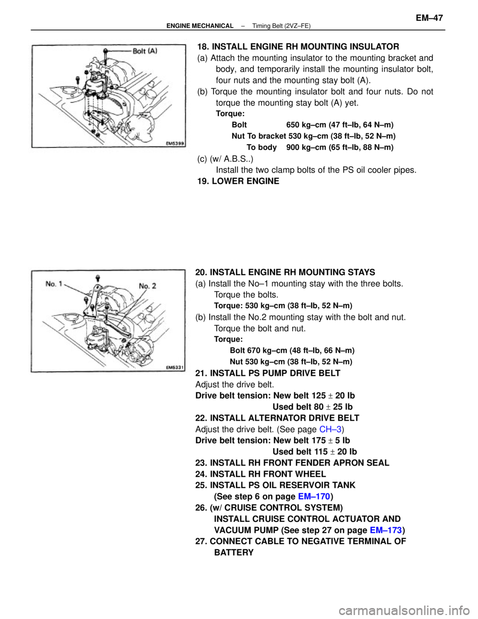
20. INSTALL ENGINE RH MOUNTING STAYS
(a) Install the No±1 mounting stay with the three bolts.
Torque the bolts.
Torque: 530 kg±cm (38 ft±Ib, 52 N±m)
(b) Install the No.2 mounting stay with the bolt and nut.
Torque the bolt and nut.
Torque:
Bolt 670 kg±cm (48 ft±Ib, 66 N±m)
Nut 530 kg±cm (38 ft±Ib, 52 N±m)
21. INSTALL PS PUMP DRIVE BELT
Adjust the drive belt.
Drive belt tension: New belt 125
+ 20 Ib
Used belt 80
+ 25 Ib
22. INSTALL ALTERNATOR DRIVE BELT
Adjust the drive belt. (See page CH±3)
Drive belt tension: New belt 175
+ 5 Ib
Used belt 115
+ 20 Ib
23. INSTALL RH FRONT FENDER APRON SEAL
24. INSTALL RH FRONT WHEEL
25. INSTALL PS OIL RESERVOIR TANK
(See step 6 on page EM±170)
26. (w/ CRUISE CONTROL SYSTEM)
INSTALL CRUISE CONTROL ACTUATOR AND
VACUUM PUMP (See step 27 on page EM±173)
27. CONNECT CABLE TO NEGATIVE TERMINAL OF
BATTERY 18. INSTALL ENGINE RH MOUNTING INSULATOR
(a) Attach the mounting insulator to the mounting bracket and
body, and temporarily install the mounting insulator bolt,
four nuts and the mounting stay bolt (A).
(b) Torque the mounting insulator bolt and four nuts. Do not
torque the mounting stay bolt (A) yet.
Torque:
Bolt 650 kg±cm (47 ft±Ib, 64 N±m)
Nut To bracket 530 kg±cm (38 ft±lb, 52 N±m)
To body 900 kg±cm (65 ft±lb, 88 N±m)
(c) (w/ A.B.S..)
Install the two clamp bolts of the PS oil cooler pipes.
19. LOWER ENGINE
± ENGINE MECHANICALTiming Belt (2VZ±FE)EM±47
Page 1226 of 2389

REMOVAL OF CYLINDER HEAD
(See page EM±48)
1. DISCONNECT CABLE FROM NEGATIVE TERMINAL
OF BATTERY
2. DRAIN ENGINE COOLANT (See page CO±4)
3. (A/T)
DISCONNECT THROTTLE CABLE AND BRACKET FROM
THROTTLE BODY
4. DISCONNECT ACCELERATOR CABLE AND BRACKET
FROM THROTTLE BODY AND AIR INTAKE CHAMBER
5. REMOVE CRUISE CONTROL ACTUATOR
(See step 9 on page EM±108)
6. REMOVE AIR CLEANER HOSE
7. REMOVE ALTERNATOR (See page CH±6)
8. REMOVE OIL PRESSURE SWITCH, ENGINE HANGERS
AND ALTERNATOR UPPER BRACKET
9. RAISE VEHICLE
NOTICE: Be sure the vehicle is securely supported.
10. REMOVE RH FRONT WHEEL
11. REMOVE ENGINE RH UNDER COVER
12. REMOVE SUSPENSION LOWER CROSSMEMBER
(See step 20 on page EM±109)
13. DISCONNECT FRONT EXHAUST PIPE FROM
CATALYTIC CONVERTER
(See step 25 on page EM±110)
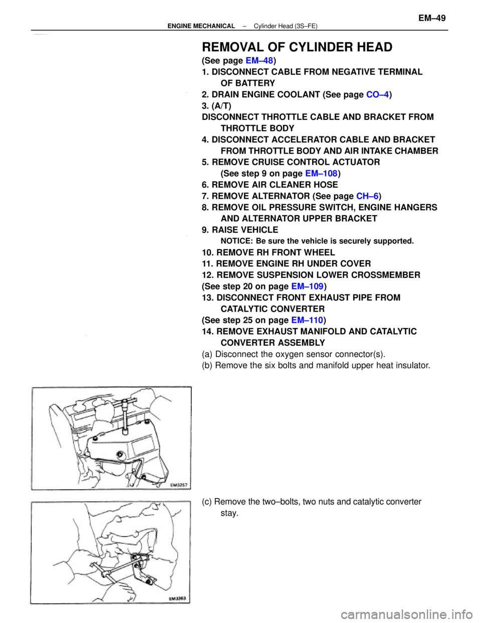
14. REMOVE EXHAUST MANIFOLD AND CATALYTIC
CONVERTER ASSEMBLY
(a) Disconnect the oxygen sensor connector(s).
(b) Remove the six bolts and manifold upper heat insulator.
(c) Remove the two±bolts, two nuts and catalytic converter
stay.
± ENGINE MECHANICALCylinder Head (3S±FE)EM±49
Page 1250 of 2389
21. CONNECT FRONT EXHAUST PIPE TO CATALYTIC
CONVERTER
(See step 12 on page EM±136)
22. INSTALL SUSPENSION LOWER CROSSMEMBER
(See step 17 on page EM±136)
23. INSTALL ENGINE RH UNDER COVER
24. INSTALL RH FRONT WHEEL
25. LOWER VEHICLE(d) Install the manifold lower heat insulator with the six
bolts.
(e) Connect the oxygen sensor connector(s). (b) Install the exhaust manifold and catalytic converter as-
sembly with new six nuts.
Torque: 500 kg±cm (37 ft±Ib, 48 N±m)
20. INSTALL EXHAUST MANIFOLD AND CATALYTIC
CONVERTER ASSEMBLY
(a) Install a gasket.
(c) Install the catalytic converter stay with the two bolts and
two nuts.
± ENGINE MECHANICALCylinder Head (3S±FE)EM±73