1986 TOYOTA CAMRY V20 oil filter
[x] Cancel search: oil filterPage 1315 of 2389
32. INSTALL BATTERY
33. FILL WITH ENGINE COOLANT (See page CO±5)
Capacity (w/ Heater):
M/T 6.4 liters (6.8 US qts, 5.6 Imp. qts)
A/T (2WD) 6.3 liters (6.7 US qts, 5.5 Imp. qts)
A/T (4WD) 6.8 liters (7.2 US qts, 6.0 Imp. qts)
34. FILL WITH ENGINE OIL (See page LU±8)
Capacity:
Drain and refill
w/ Oil filter change
3.9 liters (4.1 US qts, 3.4 Imp. qts)
w/o Oil filter change
3.7 liters (3.9 US qts, 3.3 Imp. qts)
Dry fill 4.3 liters (4.5 US qts, 3.8 Imp. qts)
35. START ENGINE AND CHECK FOR LEAKS
36. PERFORM ENGINE ADJUSTMENT
(a) Adjust the alternator drive belt.
(See page CH±3)
Drive belt tension:
w/ A/C New belt 175 + 5 lb
Used belt 130 + 10 lb
w/o A/C New belt 125 + 25 lb
Used belt 95 + 20 lb
(b) Adjust the PS drive belt.
Drive belt tension: New belt 125 + 25 lb
Used belt 80 + 20 lb
(c) Adjust the ignition timing.
(See steps 7 to 10 on pages IG±16 and 17)
Ignition timing:
10° BTDC @ idle
(w/ Terminals TE 1 and E1 connected)
(d) Adjust the valve. clearance. (See page EM±11)
Valve clearance:
Intake 0.19 ± 0.29 mm (0.007 ± 0.011 in.)
Exhaust 0.28 ± 0.38 mm (0.011 ± 0.015 in.)
37. INSTALL HOOD
38. PERFORM ROAD TEST
Check for abnormal noise, shock, slippage, correct shift
points and smooth operation.
39. RECHECK ENGINE COOLANT AND ENGINE OIL
LEVELS
± ENGINE MECHANICALCylinder Block (3S±FE)EM±138
Page 1317 of 2389
REMOVAL OF ENGINE
1. REMOVE BATTERY
Disconnect the grand strap.
2. DRAIN ENGINE COOLANT (See page CO±5)
3. REMOVE HOOD
4. REMOVE ENGINE UNDER COVERS
5. DRAIN ENGINE COOLANT (See page CO±5)
6. DRAIN ENGINE OIL
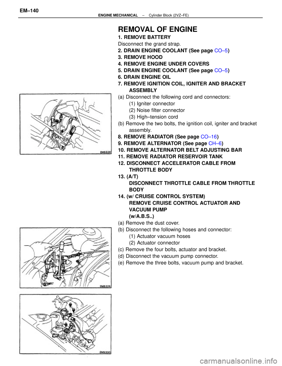
7. REMOVE IGNITION COIL, IGNITER AND BRACKET
ASSEMBLY
(a) Disconnect the following cord and connectors:
(1) Igniter connector
(2) Noise filter connector
(3) High±tension cord
(b) Remove the two bolts, the ignition coil, igniter and bracket
assembly.
8. REMOVE RADIATOR (See page CO±16)
9. REMOVE ALTERNATOR (See page CH±6)
10. REMOVE ALTERNATOR BELT ADJUSTING BAR
11. REMOVE RADIATOR RESERVOIR TANK
12. DISCONNECT ACCELERATOR CABLE FROM
THROTTLE BODY
13. (A/T)
DISCONNECT THROTTLE CABLE FROM THROTTLE
BODY
14. (w/ CRUISE CONTROL SYSTEM)
REMOVE CRUISE CONTROL ACTUATOR AND
VACUUM PUMP
(w/A.B.S..)
(a) Remove the dust cover.
(b) Disconnect the following hoses and connector:
(1) Actuator vacuum hoses
(2) Actuator connector
(c) Remove the four bolts, actuator and bracket.
(d) Disconnect the vacuum pump connector.
(e) Remove the three bolts, vacuum pump and bracket.
± ENGINE MECHANICALCylinder Block (2VZ±FE)EM±140
Page 1323 of 2389
PREPARATION FOR DISASSEMBLY
1. (M/T)
REMOVE CLUTCH COVER AND DISC
2. (M/T)
REMOVE FLYWHEEL
3. (A/T)
REMOVE DRIVE PLATE
4 REMOVE REAR END PLATE
Remove the bolt and end plate.
5. INSTALL ENGINE TO ENGINE STAND FOR
DISASSEMBLY
6. REMOVE DISTRIBUTOR (See page IG±18)
7. REMOVE TIMING BELT AND PULLEYS
(See page EM±34)
8. REMOVE CYLINDER HEADS (See page EM±76)
9. REMOVE WATER PUMP (See page CO±9)
10. REMOVE OIL PAN AND OIL PUMP
(See page LU±17)
11. REMOVE OIL FILTER (See page LU±7)
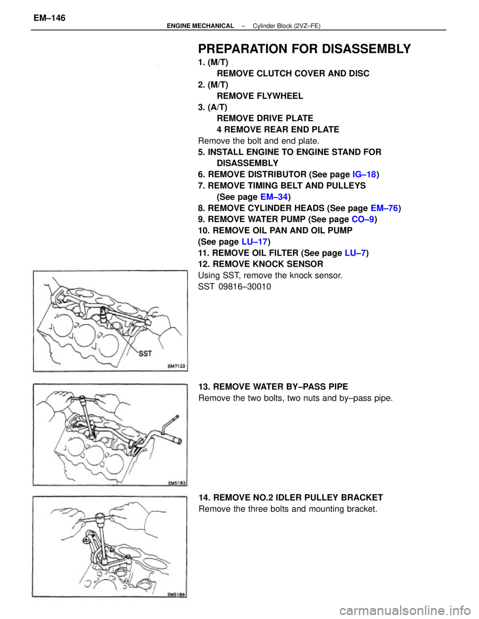
12. REMOVE KNOCK SENSOR
Using SST, remove the knock sensor.
SST 09816±30010
13. REMOVE WATER BY±PASS PIPE
Remove the two bolts, two nuts and by±pass pipe.
14. REMOVE NO.2 IDLER PULLEY BRACKET
Remove the three bolts and mounting bracket.
± ENGINE MECHANICALCylinder Block (2VZ±FE)EM±146
Page 1345 of 2389
4. INSTALL OIL FILTER (See page LU±7)
5. INSTALL OIL PUMP AND OIL PAN
(See page LU±14)
6. INSTALL WATER PUMP (See page CO±6)
7. INSTALL CYLINDER HEADS
(See pages EM±96 to 106)
8. INSTALL PULLEYS AND TIMING BELT
(See pages EM±42 to 47)
9. INSTALL DISTRIBUTOR (See page IG±19)
10. REMOVE ENGINE STAND
11. INSTALL REAR END PLATE
Install the end plate with the bolt.
Torque: 75 kg±cm (65 in.±Ib, 7.4 N±m)
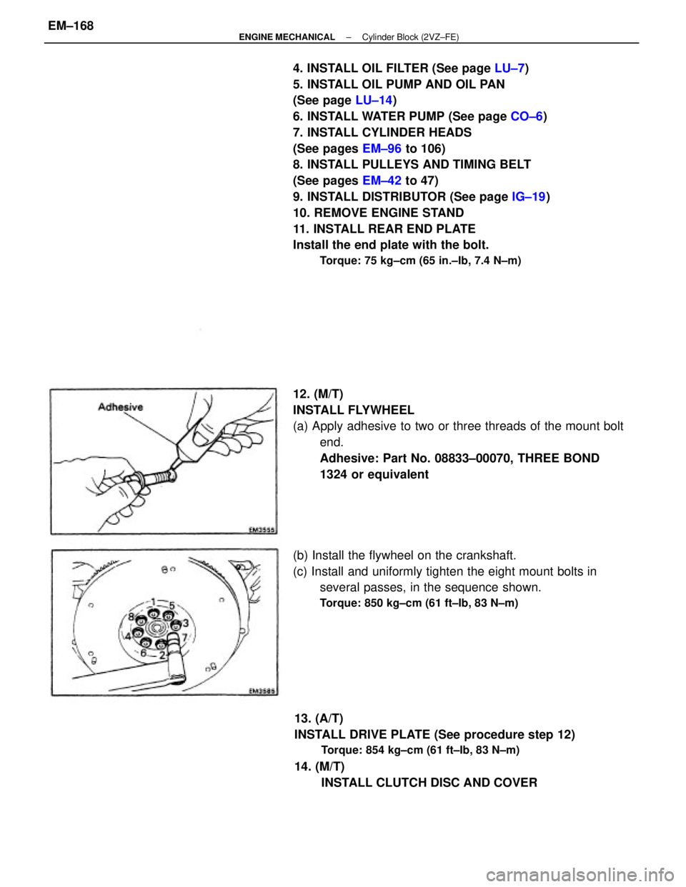
12. (M/T)
INSTALL FLYWHEEL
(a) Apply adhesive to two or three threads of the mount bolt
end.
Adhesive: Part No. 08833±00070, THREE BOND
1324 or equivalent
13. (A/T)
INSTALL DRIVE PLATE (See procedure step 12)
Torque: 854 kg±cm (61 ft±Ib, 83 N±m)
14. (M/T)
INSTALL CLUTCH DISC AND COVER (b) Install the flywheel on the crankshaft.
(c) Install and uniformly tighten the eight mount bolts in
several passes, in the sequence shown.
Torque: 850 kg±cm (61 ft±Ib, 83 N±m)
± ENGINE MECHANICALCylinder Block (2VZ±FE)EM±168
Page 1351 of 2389
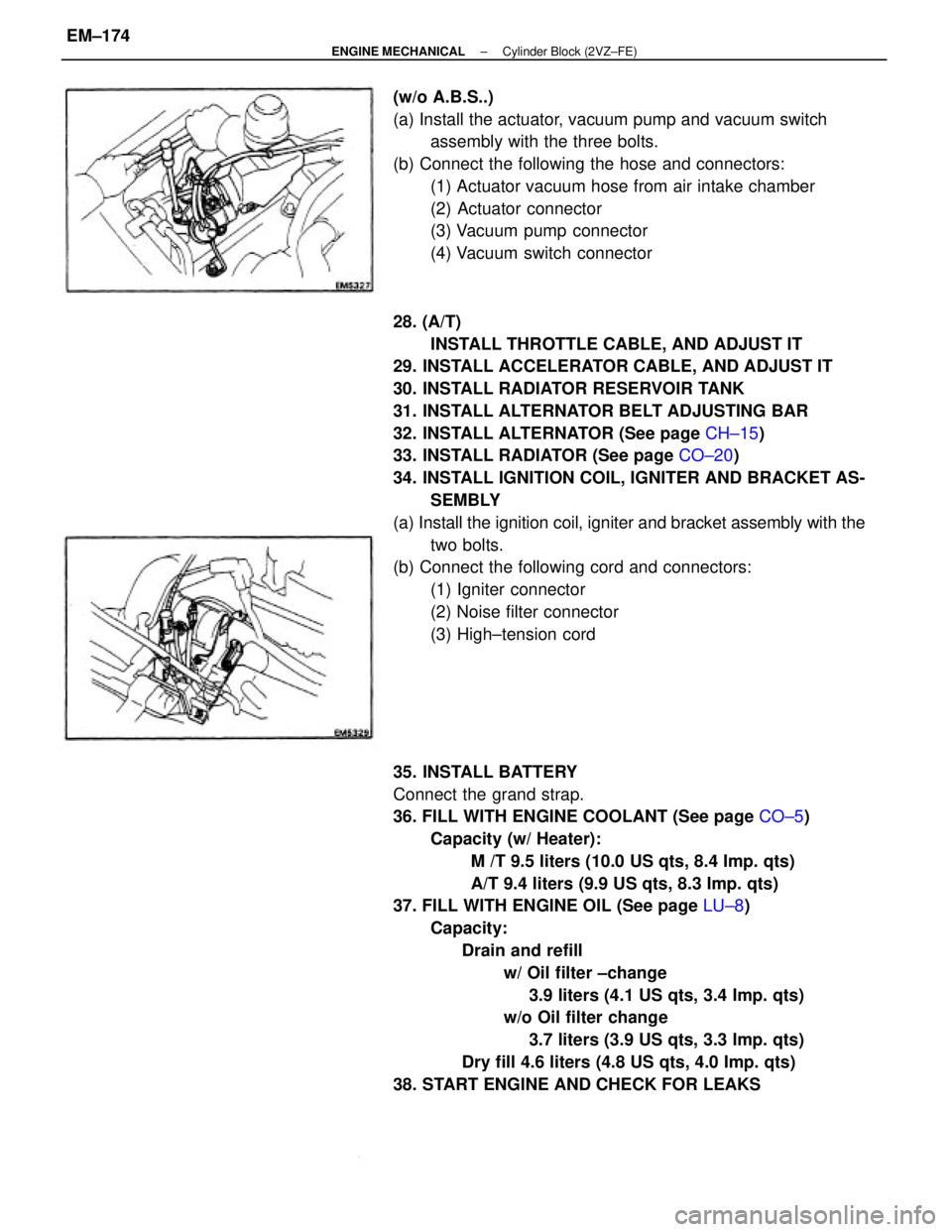
28. (A/T)
INSTALL THROTTLE CABLE, AND ADJUST IT
29. INSTALL ACCELERATOR CABLE, AND ADJUST IT
30. INSTALL RADIATOR RESERVOIR TANK
31. INSTALL ALTERNATOR BELT ADJUSTING BAR
32. INSTALL ALTERNATOR (See page CH±15)
33. INSTALL RADIATOR (See page CO±20)
34. INSTALL IGNITION COIL, IGNITER AND BRACKET AS-
SEMBLY
(a) Install the ignition coil, igniter and bracket assembly with the
two bolts.
(b) Connect the following cord and connectors:
(1) Igniter connector
(2) Noise filter connector
(3) High±tension cord
35. INSTALL BATTERY
Connect the grand strap.
36. FILL WITH ENGINE COOLANT (See page CO±5)
Capacity (w/ Heater):
M /T 9.5 liters (10.0 US qts, 8.4 Imp. qts)
A/T 9.4 liters (9.9 US qts, 8.3 Imp. qts)
37. FILL WITH ENGINE OIL (See page LU±8)
Capacity:
Drain and refill
w/ Oil filter ±change
3.9 liters (4.1 US qts, 3.4 Imp. qts)
w/o Oil filter change
3.7 liters (3.9 US qts, 3.3 Imp. qts)
Dry fill 4.6 liters (4.8 US qts, 4.0 Imp. qts)
38. START ENGINE AND CHECK FOR LEAKS (w/o A.B.S..)
(a) Install the actuator, vacuum pump and vacuum switch
assembly with the three bolts.
(b) Connect the following the hose and connectors:
(1) Actuator vacuum hose from air intake chamber
(2) Actuator connector
(3) Vacuum pump connector
(4) Vacuum switch connector
± ENGINE MECHANICALCylinder Block (2VZ±FE)EM±174
Page 1861 of 2389
PRECAUTIONS FOR VEHICLES EQUIPPED WITH A
CATALYTIC CONVERTER
CAUTION: If large amounts of unburned gasoline flow into the converter, it may overheat
and create a fire hazard. To prevent this, observe the following precautions and
explain them to your customer.
1. Use only unleaded gasoline.
2. Avoid prolonged idling.
Avoid running the engine at idle speed for more than 20
minutes.
3. Avoid spark jump test.
(a) Spark jump test only when absolutely necessary. Perform this test as rapidly as pos-
sible.
(b) While testing, never race the engine.
4. Avoid prolonged engine compression measurement.
Engine compression tests must be made as rapidly as possible.
5. Do not run engine when fuel tank is nearly empty.
This may cause the engine to misfire and create an extra
load on the converter.
6. Avoid coasting with ignition turned off and prolonged braking.
7. Do not dispose of used catalyst along with parts contaminated with gasoline or oil.(f) When steam cleaning an engine, protect the distribu-
tor, air filter and VCV from water.
(g) Never use an impact wrench to remove or install tem-
perature switches or temperature sensors.
(h) When checking continuity at the wire connector, insert
the tester probe carefully to prevent terminals from
bending.
(i) When using a vacuum gauge, never force the hose
onto a connector that is too large. Use a step±down
adapter instead. Once the hose has been stretched,
it may leak.
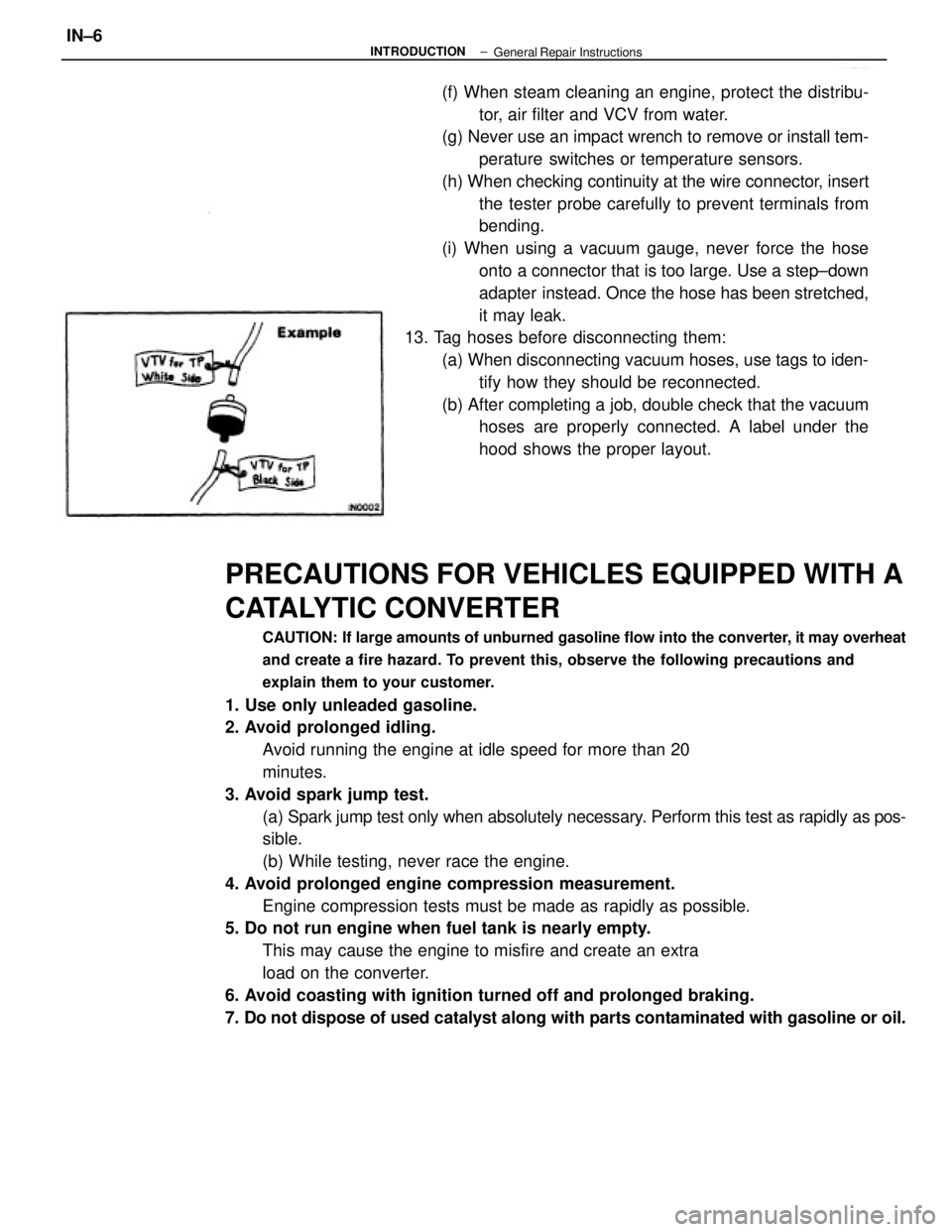
13. Tag hoses before disconnecting them:
(a) When disconnecting vacuum hoses, use tags to iden-
tify how they should be reconnected.
(b) After completing a job, double check that the vacuum
hoses are properly connected. A label under the
hood shows the proper layout.
± INTRODUCTIONIN±6General Repair Instructions
Page 1862 of 2389
PRECAUTIONS FOR VEHICLES EQUIPPED WITH A
CATALYTIC CONVERTER
CAUTION: If large amounts of unburned gasoline flow into the converter, it may overheat
and create a fire hazard. To prevent this, observe the following precautions and
explain them to your customer.
1. Use only unleaded gasoline.
2. Avoid prolonged idling.
Avoid running the engine at idle speed for more than 20
minutes.
3. Avoid spark jump test.
(a) Spark jump test only when absolutely necessary. Perform this test as rapidly as pos-
sible.
(b) While testing, never race the engine.
4. Avoid prolonged engine compression measurement.
Engine compression tests must be made as rapidly as possible.
5. Do not run engine when fuel tank is nearly empty.
This may cause the engine to misfire and create an extra
load on the converter.
6. Avoid coasting with ignition turned off and prolonged braking.
7. Do not dispose of used catalyst along with parts contaminated with gasoline or oil.(f) When steam cleaning an engine, protect the distribu-
tor, air filter and VCV from water.
(g) Never use an impact wrench to remove or install tem-
perature switches or temperature sensors.
(h) When checking continuity at the wire connector, insert
the tester probe carefully to prevent terminals from
bending.
(i) When using a vacuum gauge, never force the hose
onto a connector that is too large. Use a step±down
adapter instead. Once the hose has been stretched,
it may leak.
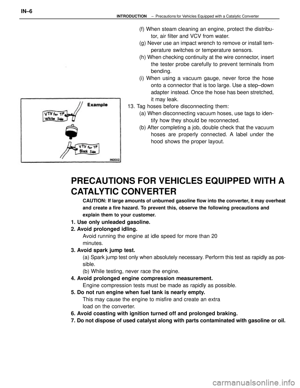
13. Tag hoses before disconnecting them:
(a) When disconnecting vacuum hoses, use tags to iden-
tify how they should be reconnected.
(b) After completing a job, double check that the vacuum
hoses are properly connected. A label under the
hood shows the proper layout.
± INTRODUCTIONPrecautions for Vehicles Equipped with a Catalytic ConverterIN±6
Page 1889 of 2389
A pressure feeding lubrication system has been adopted to supply oil to the moving parts of this engine.
The lubrication system consists of an oil pan, oil pump, oil filter and other external parts which supply oil
to the moving parts in the engine block The oil circuit is shown in the illustration at the top of the pre-
vious page. Oil from the oil pan is pumped up by the oil pump. After it passes through the oil filter, it is
fed through the various oil holes in the crankshaft and cylinder block. After passing through the cylinder
block and performing its lubricating function, the oil is returned by gravity to the oil pan. A dipstick on the
center left side of the cylinder block is provided to check the oil level.
OIL PUMP
The oil pump pumps up oil from the oil pan and sends it under pressure to the various parts of the en-
gine.
An oil strainer is mounted in front of the inlet to the oil pump. The oil pump itself is a trochoid±type
pump, inside of which is a drive rotor and a driven rotor. 'When the drive rotor rotates, the driven rotor
rotates in the same direction, and since the axis of the driven rotor shaft is different from the center of
the driven rotor, the space between the two rotors is changed as they rotate. Oil is drawn in when the
space is wide and is discharged when the space in narrow.
OIL PRESSURE REGULATOR (RELIEF VALVE)
At high engine speeds, the engine oil supplied by the oil pump exceeds the capacity of the engine to
utilize it.
For that reason, the oil pressure regulator works to prevent an oversupply of oil. During normal oil sup-
ply, a coil spring and valve keep the by±pass closed, but when too much oil is being fed, the pressure
become extremely high, overpowering the force of the spring and opening the valves. This allows the
excess oil to flow through the valve and return to the oil pan.
OIL FILTER
The oil filter is a full flow type filter with a built±in paper filter element, Particles of metal from wear, air-
born dirt, carbon and other impurities can get in the oil during use and could cause accelerated wear or
seizing if allowed to circulate through the engine. The oil filter, integrated into the oil line, removes these
impurities as the oil passes through it. The filter is mounted outside the engine to simplify replacement of
the filter element.
A relief valve is also included ahead of the filter element to relieve the high oil pressure in case the filter
element becomes clogged with impurities. The relief valve opens when the oil pressure overpowers the
force of the spring. Oil passing through the relief valve by±passes the oil filter and flows directly into the
main oil hole in the engine.
± LUBRICATION SYSTEMDescriptionLU±4