Page 217 of 2389

Discharging of Refrigeration System
Evacuating and Charging of
Refrigeration System
(See Air Conditioning Fundamentals and Repairs Pub. No.
36950E)
Condenser clogged
Drive belt slipping
Magnetic clutch faulty
Compressor faulty
Expansion valve faulty
Thermistor faulty
A/C amplifier faulty
Insufficient or too much refrigerant
Air or excessive compressor oil in
system
Receiver clogged
Water valve cable set faultyCheck condenser .
Check or replace drive belt
Check magnetic clutch
Check compressor
Check expansion valve
Check thermistor
Check amplifier
Check refrigerant volume
Evacuate and charge system
Evaporator clogged or frosted
Air leakage from cooling unit or air duct
Air inlet blocked
Blower motor faulty
A/C amplifier faulty
Drive belt slipping
Revolution detecting sensor faulty
(w/Power steering)
A/C amplifier faultyAC±33
AC±21
AC±23
AC±23
AC±39
AC±43
AC±45 to 47
AC±22
Repair as necessary
Replace blower motor
Check amplifierClean evaporator fins or filters
Repair as necessary
Check or replace drive belt
Check sensor
Check receiver
Reset water valve cable
A/C switch
indicator
flashingInsufficient
velocity of cool
airAC±41
AC±39 to 42 Insufficient
cooling
Check amplifier Possible cause
AC±21
AC±24AC±32
BE±79
AC±39 to 42
AC±45 to 47
AC±45 to 47 Remedy ProblemPage
± AIR CONDITIONING SYSTEMTroubleshooting Refrigeration SystemAC±17
Page 1024 of 2389
TROUBLESHOOTING
TROUBLESHOOTING HINTS
1. Engine troubles is usually not caused by the EFI system.
When troubleshooting, always first check the condition of
the other systems.
(a) Electronic source
wBattery
wFusible links
wFuses
(b) Body ground
(e) Fuel supply
wFuel leakage
wFuel filter
wFuel pump
(d) Ignition system
wSpark plugs
wHigh±tension cords
wDistributor
wIgnition coil
wIgniter
(e) Air induction system
wVacuum leaks
(f) Emission control system
wPCV system
wEGR system
(g) Others
wIgnition timing (ESA system)
wdle speed (ISC system)
wetc.
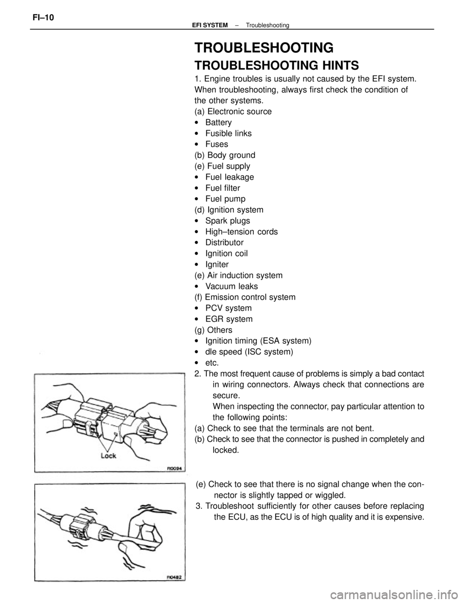
2. The most frequent cause of problems is simply a bad contact
in wiring connectors. Always check that connections are
secure.
When inspecting the connector, pay particular attention to
the following points:
(a) Check to see that the terminals are not bent.
(b) Check to see that the connector is pushed in completely and
locked.
(e) Check to see that there is no signal change when the con-
nector is slightly tapped or wiggled.
3. Troubleshoot sufficiently for other causes before replacing
the ECU, as the ECU is of high quality and it is expensive.
± EFI SYSTEMTroubleshootingFI±10
Page 1027 of 2389
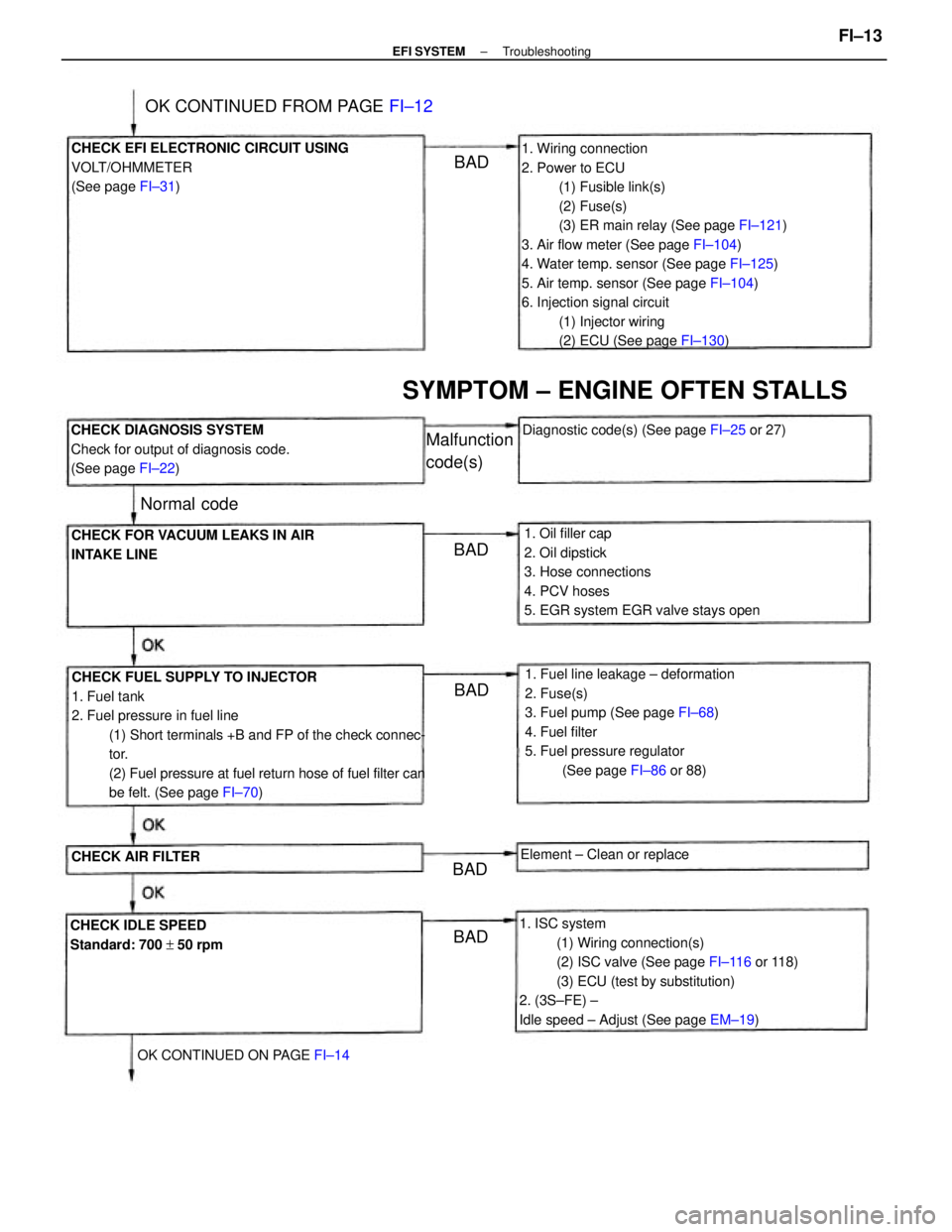
1. Wiring connection
2. Power to ECU
(1) Fusible link(s)
(2) Fuse(s)
(3) ER main relay (See page FI±121)
3. Air flow meter (See page FI±104)
4. Water temp. sensor (See page FI±125)
5. Air temp. sensor (See page FI±104)
6. Injection signal circuit
(1) Injector wiring
(2) ECU (See page FI±130)
CHECK FUEL SUPPLY TO INJECTOR
1. Fuel tank
2. Fuel pressure in fuel line
(1) Short terminals +B and FP of the check connec-
tor.
(2) Fuel pressure at fuel return hose of fuel filter can
be felt. (See page FI±70)
1. ISC system
(1) Wiring connection(s)
(2) ISC valve (See page FI±116 or 118)
(3) ECU (test by substitution)
2. (3S±FE) ±
Idle speed ± Adjust (See page EM±19) 1. Fuel line leakage ± deformation
2. Fuse(s)
3. Fuel pump (See page FI±68)
4. Fuel filter
5. Fuel pressure regulator
(See page FI±86 or 88) 1. Oil filler cap
2. Oil dipstick
3. Hose connections
4. PCV hoses
5. EGR system EGR valve stays open CHECK EFI ELECTRONIC CIRCUIT USING
VOLT/OHMMETER
(See page FI±31)
CHECK DIAGNOSIS SYSTEM
Check for output of diagnosis code.
(See page FI±22)
CHECK FOR VACUUM LEAKS IN AIR
INTAKE LINE
SYMPTOM ± ENGINE OFTEN STALLS
CHECK IDLE SPEED
Standard: 700 + 50 rpmDiagnostic code(s) (See page FI±25 or 27)
OK CONTINUED FROM PAGE FI±12
OK CONTINUED ON PAGE FI±14Element ± Clean or replace
CHECK AIR FILTER
Malfunction
code(s)
Normal code
BADBAD
BAD
BADBAD
± EFI SYSTEMTroubleshootingFI±13
Page 1029 of 2389
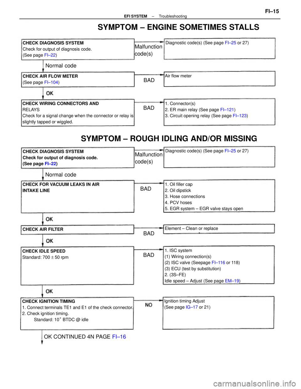
1. ISC system
(1) Wiring connection(s)
(2) ISC valve (Seepage FI±116 or 118)
(3) ECU (test by substitution)
2. (3S±FE)
Idle speed ± Adjust (See page EM±19)
CHECK IGNITION TIMING
1. Connect terminals TE1 and E1 of the check connector.
2. Check ignition timing.
Standard: 10° BTDC @ idle CHECK WIRING CONNECTORS AND
RELAYS
Check for a signal change when the connector or relay is
slightly tapped or wiggled.
1. Oil filler cap
2. Oil dipstick
3. Hose connections
4. PCV hoses
5. EGR system ± EGR valve stays open1. Connector(s)
2. ER main relay (See page FI±121)
3. Circuit opening relay (See page FI±123) CHECK DIAGNOSIS SYSTEM
Check for output of diagnosis code.
(See page FI±22)
CHECK DIAGNOSIS SYSTEM
Check for output of diagnosis code.
(See page FI±22)
SYMPTOM ± ENGINE SOMETIMES STALLS
SYMPTOM ± ROUGH IDLING AND/OR MISSING
CHECK FOR VACUUM LEAKS IN AIR
INTAKE LINE
Ignition timing Adjust
(See page IG±17 or 21) CHECK AIR FLOW METER
(See page FI±104)
CHECK IDLE SPEED
Standard: 700 + 50 rpmDiagnostic code(s) (See page FI±25 or 27)
Diagnostic code(s) (See page FI±25 or 27)
OK CONTINUED 4N PAGE FI±16
Element ± Clean or replace
CHECK AIR FILTER
Malfunction
code(s)
Malfunction
code(s)
Air flow meter
Normal code
Normal code
BAD
BADBAD
BAD BAD
± EFI SYSTEMTroubleshootingFI±15
Page 1032 of 2389
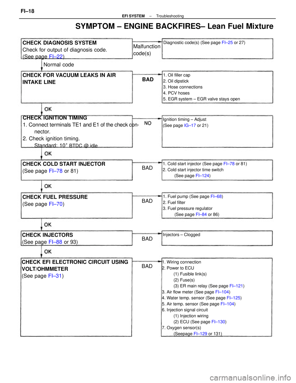
1. Wiring connection
2. Power to ECU
(1) Fusible link(s)
(2) Fuse(s)
(3) ER main relay (See page FI±121)
3. Air flow meter (See page FI±104)
4. Water temp. sensor (See page FI±125)
5. Air temp. sensor (See page FI±104)
6. Injection signal circuit
(1) Injection wiring
(2) ECU (See page FI±130)
7. Oxygen sensor(s)
(Seepage FI±129 or 131)
CHECK IGNITION TIMING
1. Connect terminals TE1 and E1 of the check con-
nector.
2. Check ignition timing.
Standard: 10
° BTDC @ idle
1. Oil filler cap
2. Oil dipstick
3. Hose connections
4. PCV hoses
5. EGR system ± EGR valve stays open
CHECK EFI ELECTRONIC CIRCUIT USING
VOLT/OHMMETER
(See page FI±31)
1. Cold start injector (See page FI±78 or 81)
2. Cold start injector time switch
(See page FI±124)
1. Fuel pump (See page FI±68)
2. Fuel filter
3. Fuel pressure regulator
(See page FI±84 or 86)
CHECK DIAGNOSIS SYSTEM
Check for output of diagnosis code.
(See page FI±22)
SYMPTOM ± ENGINE BACKFIRES± Lean Fuel Mixture
CHECK FOR VACUUM LEAKS IN AIR
INTAKE LINE
CHECK COLD START INJECTOR
(See page FI±78 or 81)
CHECK FUEL PRESSURE
(See page FI±70)
Diagnostic code(s) (See page FI±25 or 27)
Ignition timing ± Adjust
(See page IG±17 or 21)
CHECK INJECTORS
(See page FI±88 or 93)Injectors ± Clogged
Malfunction
code(s)
Normal code
BAD
BAD
BAD BAD
BAD
± EFI SYSTEMTroubleshootingFI±18
Page 1034 of 2389
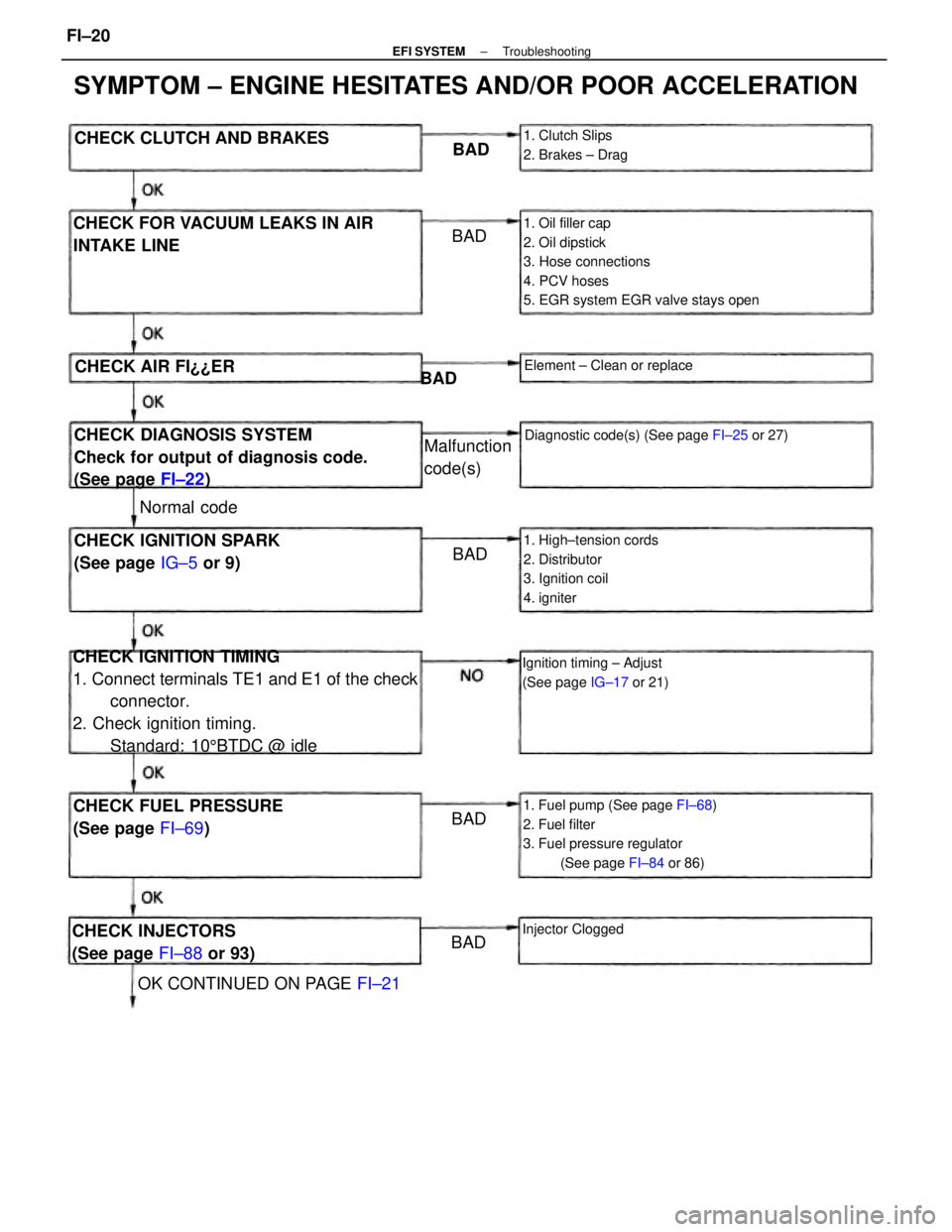
CHECK IGNITION TIMING
1. Connect terminals TE1 and E1 of the check
connector.
2. Check ignition timing.
Standard: 105BTDC @ idle
1. Oil filler cap
2. Oil dipstick
3. Hose connections
4. PCV hoses
5. EGR system EGR valve stays open
SYMPTOM ± ENGINE HESITATES AND/OR POOR ACCELERATION
1. Fuel pump (See page FI±68)
2. Fuel filter
3. Fuel pressure regulator
(See page FI±84 or 86)
CHECK DIAGNOSIS SYSTEM
Check for output of diagnosis code.
(See page FI±22) CHECK FOR VACUUM LEAKS IN AIR
INTAKE LINE
1. High±tension cords
2. Distributor
3. Ignition coil
4. igniterCHECK IGNITION SPARK
(See page IG±5 or 9)
CHECK FUEL PRESSURE
(See page FI±69)
Diagnostic code(s) (See page FI±25 or 27)
Ignition timing ± Adjust
(See page IG±17 or 21)
CHECK INJECTORS
(See page FI±88 or 93)
OK CONTINUED ON PAGE FI±21 CHECK CLUTCH AND BRAKES
1. Clutch Slips
2. Brakes ± Drag
Element ± Clean or replace
Malfunction
code(s)
Injector Clogged
CHECK AIR FI¿¿ER
Normal codeBAD
BADBAD
BADBAD BAD
± EFI SYSTEMTroubleshootingFI±20
Page 1183 of 2389
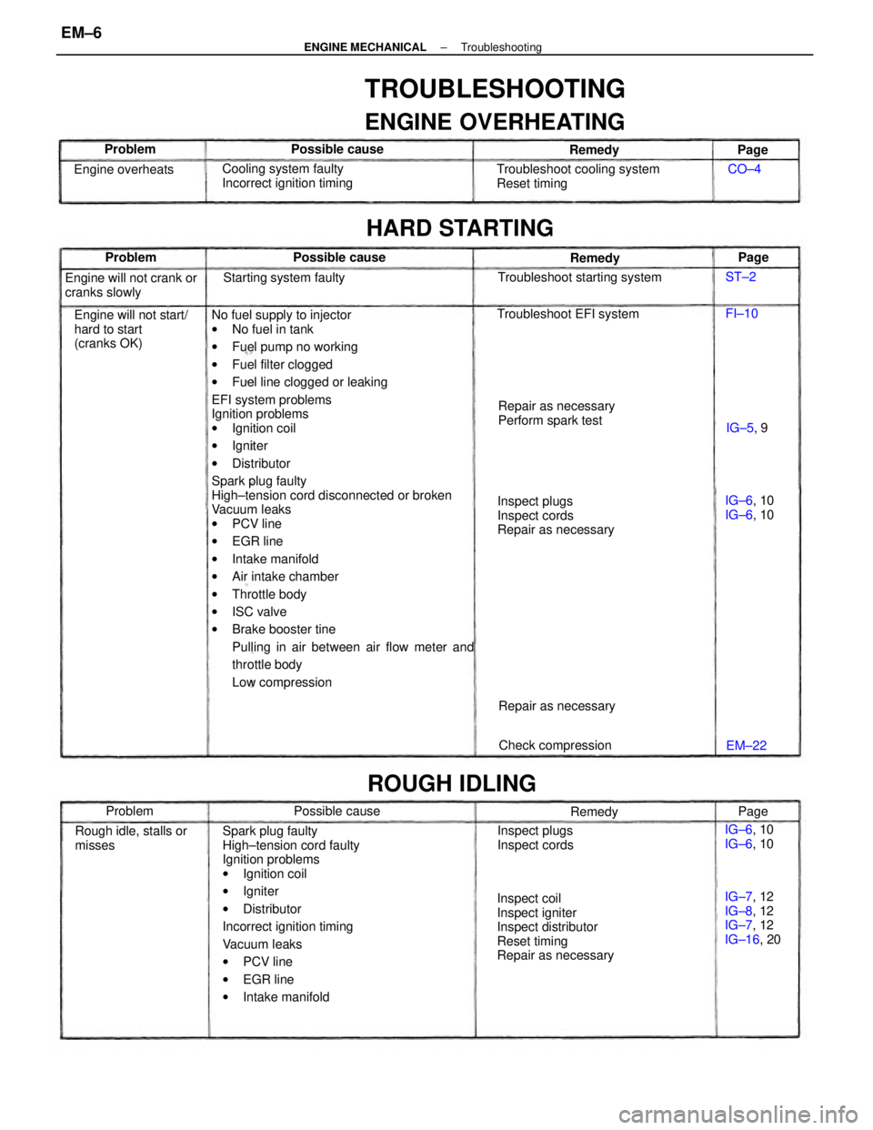
No fuel supply to injector
wNo fuel in tank
wFuel pump no working
wFuel filter clogged
wFuel line clogged or leaking
EFI system problems
Ignition problems
wIgnition coil
wIgniter
wDistributor
Spark plug faulty
High±tension cord disconnected or broken
Vacuum leaks
wPCV line
wEGR line
wIntake manifold
wAir intake chamber
wThrottle body
wISC valve
wBrake booster tine
Pulling in air between air flow meter and
throttle body
Low compression
Spark plug faulty
High±tension cord faulty
Ignition problems
wIgnition coil
wIgniter
wDistributor
Incorrect ignition timing
Vacuum leaks
wPCV line
wEGR line
wIntake manifold
TROUBLESHOOTING
ENGINE OVERHEATING
Inspect coil
Inspect igniter
Inspect distributor
Reset timing
Repair as necessaryInspect plugs
Inspect cords
Repair as necessary Troubleshoot cooling system
Reset timing
Engine will not start/
hard to start
(cranks OK)Cooling system faulty
Incorrect ignition timing
Repair as necessary
Perform spark test Engine will not crank or
cranks slowly
IG±7, 12
IG±8, 12
IG±7, 12
IG±16, 20 Rough idle, stalls or
misses
HARD STARTING
Troubleshoot starting system
Inspect plugs
Inspect cords Troubleshoot EFI system
ROUGH IDLING
Starting system faulty
Check compression Repair as necessary Engine overheats
IG±6, 10
IG±6, 10 IG±6, 10
IG±6, 10 Possible cause
Possible cause Possible cause
Remedy Remedy
Problem
Remedy Problem Problem
IG±5, 9
EM±22Page
Page
Page CO±4
FI±10 ST±2
± ENGINE MECHANICALTroubleshootingEM±6
Page 1187 of 2389
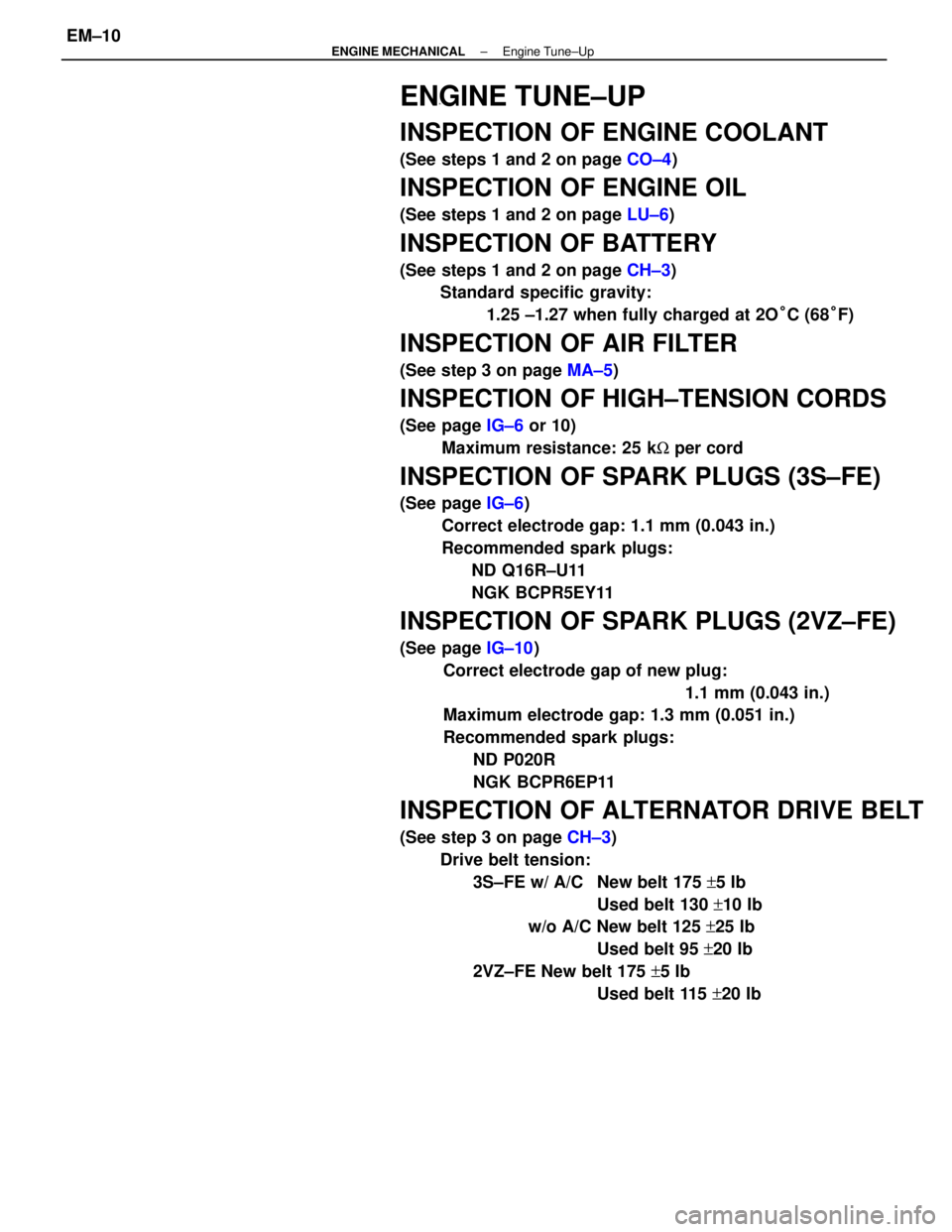
ENGINE TUNE±UP
INSPECTION OF ENGINE COOLANT
(See steps 1 and 2 on page CO±4)
INSPECTION OF ENGINE OIL
(See steps 1 and 2 on page LU±6)
INSPECTION OF BATTERY
(See steps 1 and 2 on page CH±3)
Standard specific gravity:
1.25 ±1.27 when fully charged at 2O°C (68°F)
INSPECTION OF AIR FILTER
(See step 3 on page MA±5)
INSPECTION OF HIGH±TENSION CORDS
(See page IG±6 or 10)
Maximum resistance: 25 kW per cord
INSPECTION OF SPARK PLUGS (3S±FE)
(See page IG±6)
Correct electrode gap: 1.1 mm (0.043 in.)
Recommended spark plugs:
ND Q16R±U11
NGK BCPR5EY11
INSPECTION OF SPARK PLUGS (2VZ±FE)
(See page IG±10)
Correct electrode gap of new plug:
1.1 mm (0.043 in.)
Maximum electrode gap: 1.3 mm (0.051 in.)
Recommended spark plugs:
ND P020R
NGK BCPR6EP11
INSPECTION OF ALTERNATOR DRIVE BELT
(See step 3 on page CH±3)
Drive belt tension:
3S±FE w/ A/C New belt 175 +5 Ib
Used belt 130 +10 Ib
w/o A/C New belt 125 +25 Ib
Used belt 95 +20 Ib
2VZ±FE New belt 175 +5 Ib
Used belt 115 +20 Ib
± ENGINE MECHANICALEngine Tune±UpEM±10