1986 CHEVROLET CORVAIR warning
[x] Cancel search: warningPage 5 of 56
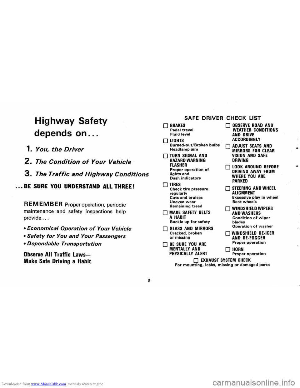
Downloaded from www.Manualslib.com manuals search engine Highway Safety
depends on ...
1. You, the Driver
2. The Condition of Your Vehicle
3. The Traffic and Highway Conditions
••• BE SURE YOU UNDERSTAND ALL THREE!
REMEMBER Proper operation, periodic
maintenance and safety inspections help
provide
...
• Economical Operation of Your Vehicle
• Safety for You and Your Passengers
• Dependable Transportation
Observe All Traffic Laws
Make Safe Driving a Habit
2
SAFE DRIVER CHECK LIST
o BRAKES Pedal travel Fluid level
o LIGHTS Burned-out/Broken bulbs Headlamp aim
o TURN SIGNAL AND HAZARD WARNING FLASHER Proper operation of lights and Dash indicators
o TIRES Check tire pressure regularly Cuts and bruises Uneven wear Remaining tread
o MAKE SAFETY BELTS A HABIT Buckle up for safety
o GLASS AND MIRRORS Cracked, broken or missing
o BE SURE YOU ARE
o OBSERVE ROAD AND WEATHER CONDITIONS AND DRIVE ACCORDINGLY
o ADJUST SEATS AND MIRRORS FOR CLEAR VISION AND SAFE DRIVING
o LOOK AROUND BEFORE DRIVING AWAY FROM WHERE YOU ARE PARKED
o STEERING AND WHEEL ALIGNMENT Excessive play in wheel Bent wheels
o WINDSHIELD WIPERS AND WASHERS Condition of wiper blades Operation of washer
o WINDSHIELD DE-ICER AND DE-FOGGER Proper operation
MENTALLY AND 0 HORN PHYSICALLY ALERT Proper operation
o EXHAUST SYSTEM CHECK For mounting, leaks, missing or damaged parts
Page 6 of 56
Downloaded from www.Manualslib.com manuals search engine ..
Don't invite car theft! An unlocked car with the
key still in the ignition offers both opportunity and temptation.
Remember always to lock ignition,
lock all doors ... TAKE THE KEY!
NOTE: Your 1968 Chevrolet features as standard equipment a buzzer device which
will activate when the driver's door is opened and the key left in the switch. Heed
its
warning-let it also serve to remind you to lock all doors.
The identification number
of your vehicle is located on the instrument panel and is
visible from the outside. It is also stamped prominently on the engine and transmission.
These precautions have been taken
for your protection to aid the apprehension of thieves
and the recovery
of stolen vehicles, engines and transmissions and to serve as a deterrent
to
theft itself.
3
Page 11 of 56
Downloaded from www.Manualslib.com manuals search engine STARTING THE ENGINE
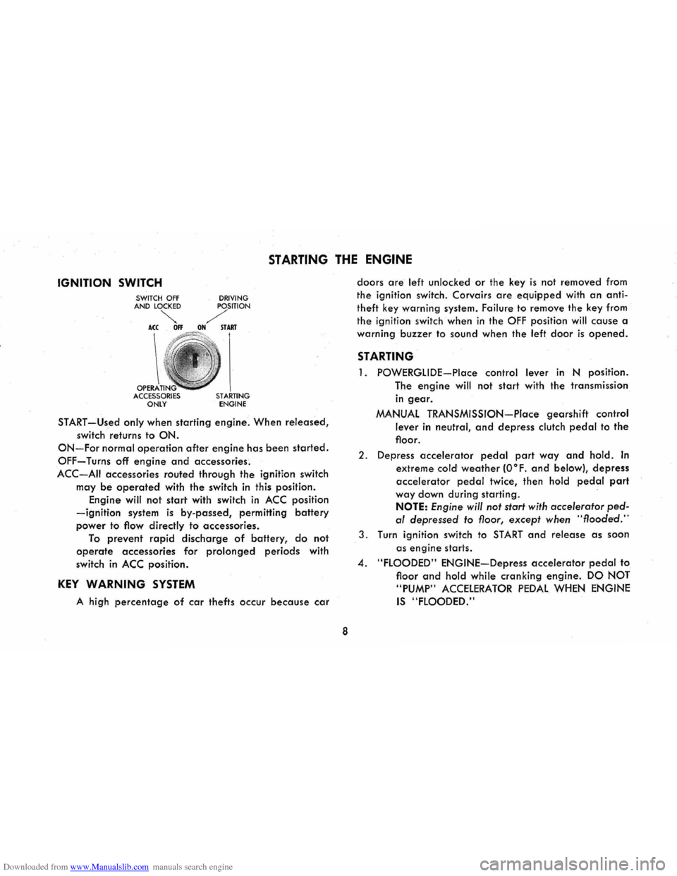
IGNITION SWITCH
OPERA ACCESSORIES ONLY DRIVING STARTING ENGINE
START-Used only when
starting engine. When released,
switch returns to ON.
ON-For normal operation after engine has been started.
OFF-Turns off engine and accessories.
ACC-AII accessories routed through the ignition switch
may
be operated with the switch in this position.
Engine will not
start with switch in ACC position
-ignition system is by-passed, permitting battery
power to flow directly to accessories.
To prevent rapid discharge of battery, do not
operate accessories for prolonged periods with
switch
in ACC position.
KEY WARNING SYSTEM
A high percentage of car thefts occur because car
8
doors are left unlocked or the key is not removed from
the ignition switch. Corvairs
are equipped with an anti
theft key warning system. Failure
to remove the key from
the ignition switch when
in the OFF position will cause a
warning
buzzer to sound when the left door is opened.
STARTING
1. POWERGLIDE-Place control lever in N position.
The
engine will not start with the transmission
in gear.
MANUAL TRANSMISSION-Place gearshift control
lever in neutral, and depress clutch pedal to the
floor.
2. Depress accelerator pedal part way and hold. In
extreme cold weather (O°F. and below), depress
accelerator pedal twice, then hold pedal part
way down during starting .
NOTE: Engine will not start with accelerator ped
al depressed to floor, except when "flooded."
3. Turn ignition switch to START and release as soon
as
engine starts .
4. "FLOODED" ENGINE-Depress accelerator pedal to
floor
and hold while cranking engine. DO NOT
"PUMP"
ACCELERATOR PEDAL WHEN ENGINE
IS "FLOODED."
Page 17 of 56
Downloaded from www.Manualslib.com manuals search engine operating, except the GEN-FAN indicator rna)' flicker
when
engine is idling.
CAUTION: If either of these indicators light
while .
car is being. -driYen, immediately follow the
procedure outlined .vnder "EMERGENCY OPER
ATING INSTRUCTIONS," so car may be driyen
to the nearest service facility.
BRAKE SYSTEM WARNING LIGHT
This dual purpose indicator light operates as
follows:
With parking brake applied the red light will light
when
the ignition switch is turned on.
As a dual service brake system warning, the red
light will come on when the brake pedal is depressed
if low pressure has developed in either the front or
rear brake system. Have your authorized Chevrolet
dealer locate and correct the trouble immediately.
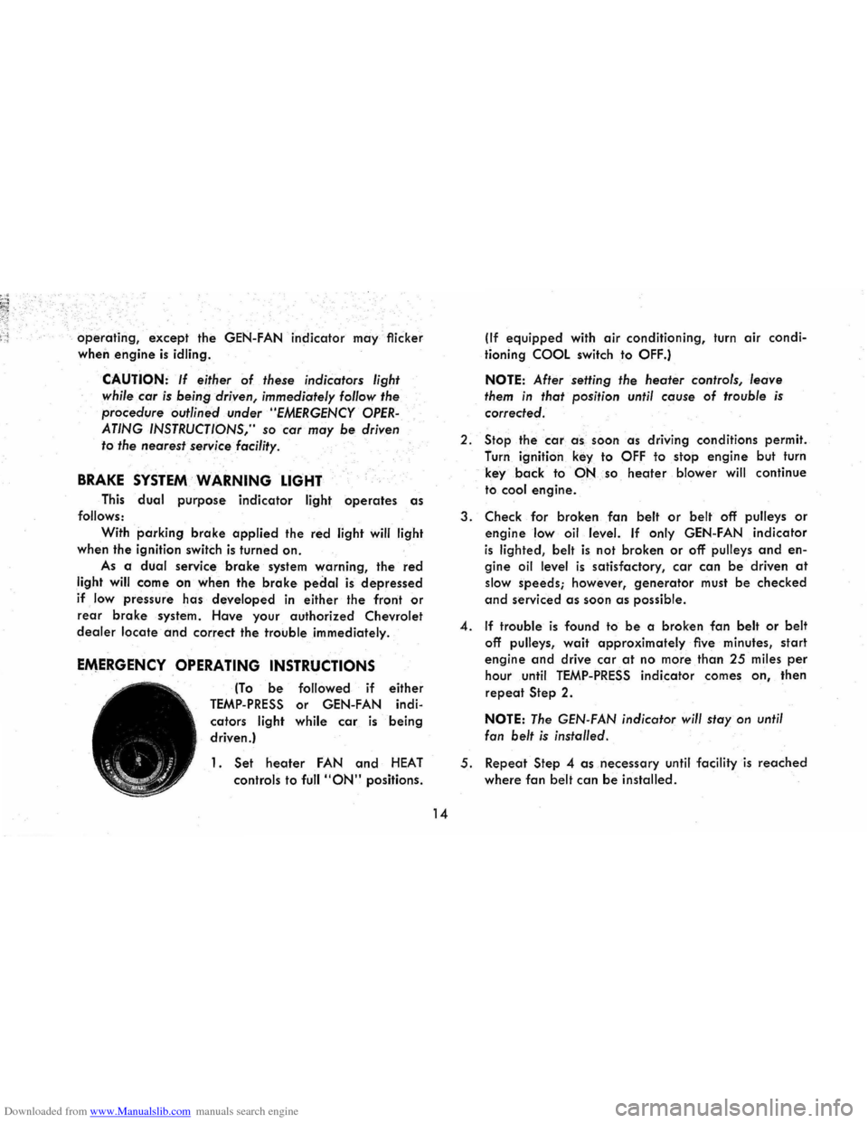
EMERGENCY OPERATING INSTRUCTIONS
(To be followed if either
TEMP-PRESS or GEN-FAN indi
cators
light while car is being
driven.)
1. Set heoter FAN and HEAT
controls to full "ON" positions.
14
(If equipped with air conditioning, turn air condi
tioning
COOL switch to OFF.)
NOTE: After setting the heater controls, leave
them in that position until cause of trouble is
corrected.
2.
Stop the car a -s , soon as driving conditions permit.
furn ignition
key to OFF to stop engine but turn
key
back to·-PNso heoter blower will continue
to
cool engine.
3. Check for broken fan belt or belt off pulleys or
engine low oil level. If only GEN-FAN indicator
is lighted, belt is not broken or off pulleys and en
gine oil level is satisfactory, car can be driven at
slow speeds; however, generator must be checked
and serviced as soon as possible.
4. If trouble is found to be a broken fan belt or belt
off pulleys, wait approximately five minutes, start
engine and drive car at no more than 25 miles per
hour until TEMP-PRESS indicator comes on, then
repeat Step 2.
NOTE: The GEN-FAN indicator will stay on until
fan
belt is installed.
5. Repeat Step 4 as necessary until facility is reached
where fan belt can be installed.
Page 18 of 56
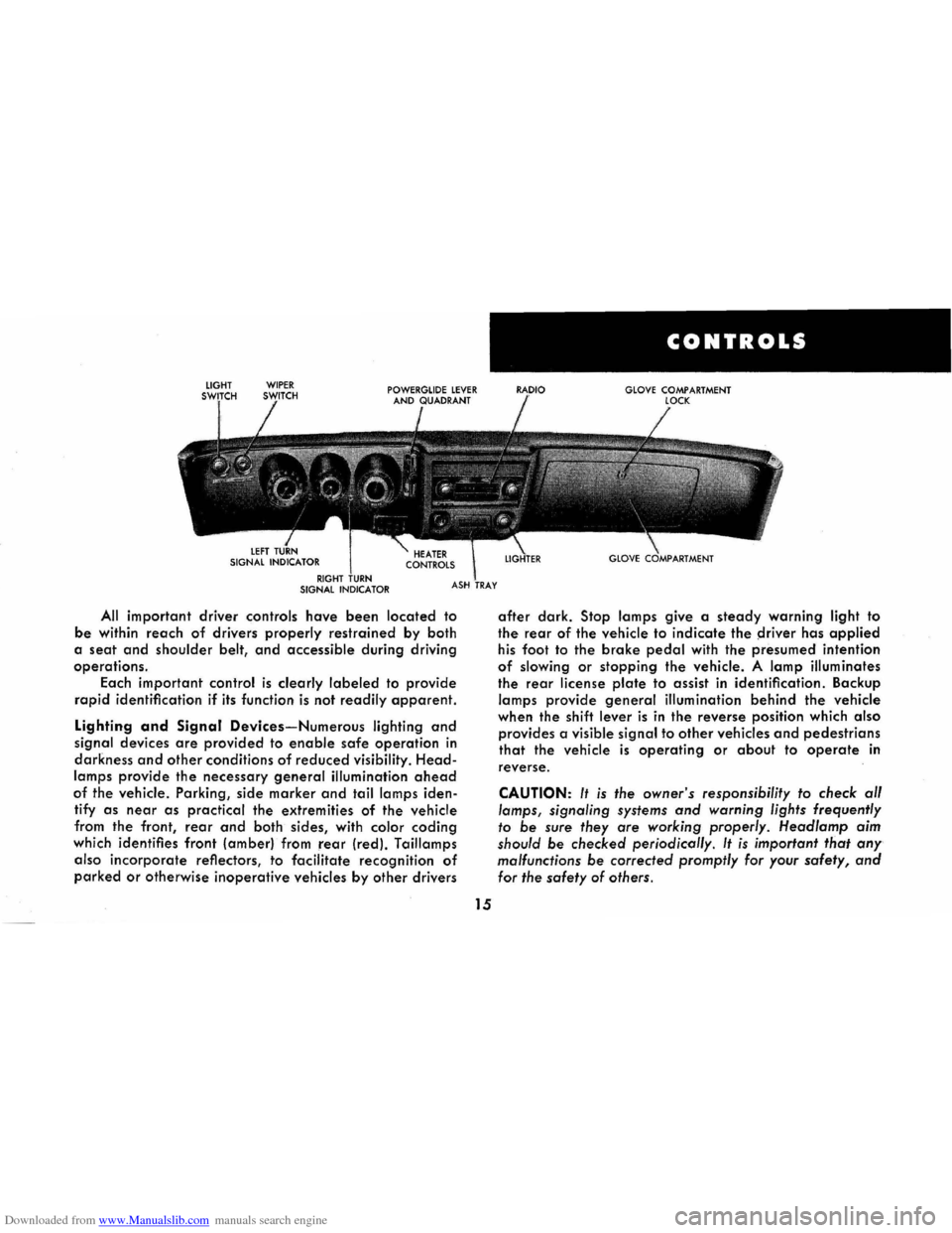
Downloaded from www.Manualslib.com manuals search engine All important driver controls have been located to
be within reach of drivers properly restrained by both
a
seat and shoulder belt, and accessible during driving
operations.
Each important
control is clearly labeled to provide
rapid identification if its function is not readily apparent.
Lighting and Signal Devices-Numerous lighting and
signal devices are provided to enable safe operation in
darkness and other conditions of reduced visibility. Head
lamps provide the necessary general illumination ahead
of the vehicle. Parking, side marker and tail lamps iden
tify
as near as practical the extremities of the vehicle
from the front,
rear and both sides, with color coding
which identifies front (amber) from rear (red). Taillamps
also
incorporate reflectors, to facilitate recognition of
parked or otherwise inoperative vehicles by other drivers
15
CONTROLS
GLOVE COMPARTMENT
after dark. Stop lamps give a steady warning light to
the rear of the vehicle to indicate the ~river has applied
his foot to the brake pedal with the presumed intention
of slowing or stopping the vehicle. A lamp illuminates
the rear license plate to assist in identification. Backup
lamps provide general illumination behind the vehicle
when the shift
lever is in the reverse position which also
provides a visible signal to other vehicles and pedestrians
that the vehicle is operating or about to operate in
reverse.
CAUTION: It is the owner's responsibility to check al/
lamps, signaling systems and warning lights frequently
to be sure they are working properly. Head/amp aim
should
be checked periodicol/y. It is important that any
malfunctions be corrected promptly for your safety, and
for the safety of others.
Page 20 of 56
Downloaded from www.Manualslib.com manuals search engine If the system is not functioning properly, a legal hand
signal should be given, since failure to indicate a turn
is considered a moving traffic violation in many states.
Always signal for a turn
at a reasonable distance before actu 'ally making it.
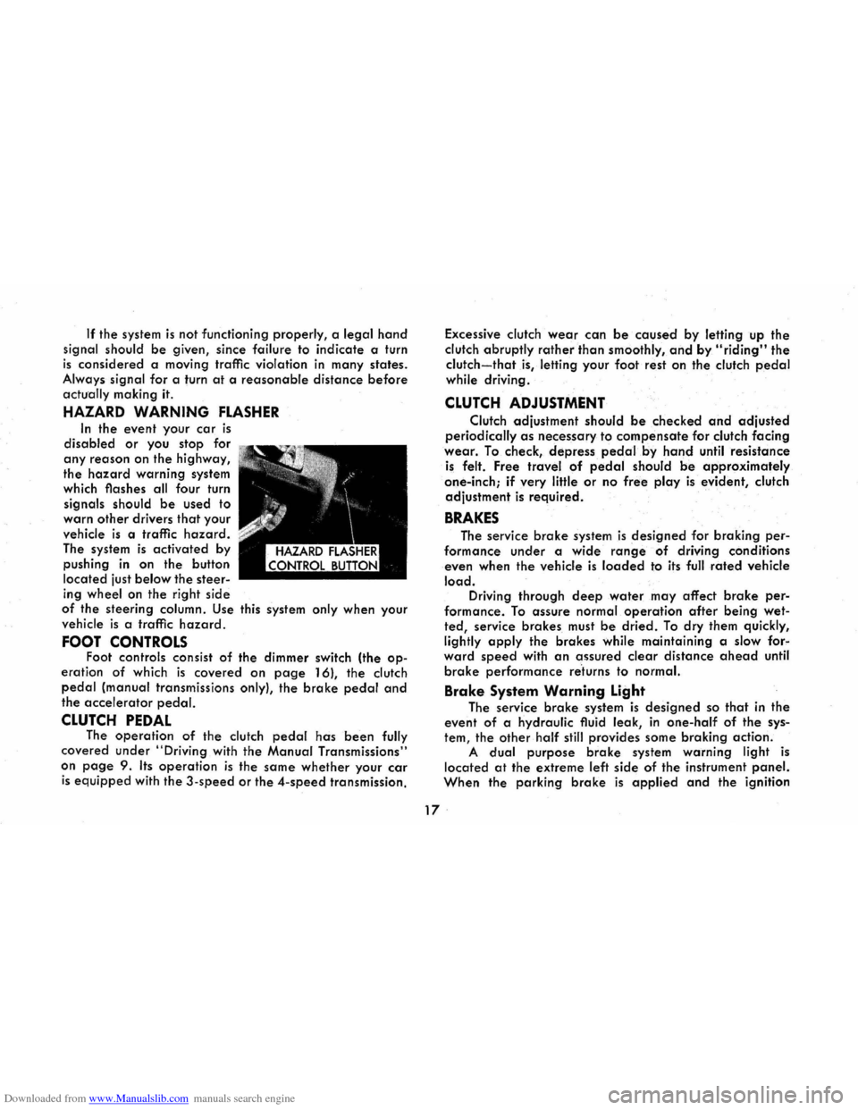
HAZARD WARNING FLASHER
In the event your car is
disabled or you stop for
any reason on the highway,
the
hazard warning system
which flashes all four turn
signals should
be used to
warn
other drivers that your
vehicle
is a traffic hazard.
The system is activated by
pushing
in on the button
located just
below the steer
ing wheel on the right side
of the steering column. Use this system only when your
vehicle
is a traffic hazard.
FOOT CONTROLS Foot controls consist of the dimmer switch (the op
eration of which is covered on page 16), the clutch
pedal (manual transmissions only), the brake pedal and
the accelerator pedal.
CLUTCH PEDAL The operation of the clutch pedal has been fully
covered under
"Driving with the Manual Transmissions"
on
page 9. Its operation is the same whether your car
is equipped with the 3-speed or the 4-speed transmission. Excessive
clutch
wear can be caused by letting up the
clutch abruptly
rather than smoothly, and by "riding" the
clutch-that is, letting your foot rest on the clutch pedal
while driving .
CLUTCH ADJUSTMENT
Clutch adjustment should be checked and adjusted
periodically as necessary to compensate for clutch facing
wear. To check, depress pedal.by hand until resistance
is felt. Free travel of pedal should be approximately
one-inch;
if very little or no free play is evident, clutch
adjustment
is required.
BRAKES
The service brake system is designed for braking per
formance under a wide range of driving conditions
even when the vehicle
is loaded to its full rated vehicle
load. Driving through deep water may affect brake per
formance. To assure normal operation after being wet
ted, service brakes must be dried. To dry them quickly,
lightly
apply the brakes while maintaining a slow for"
ward speed with an assured clear distance ahead until
brake performance re'turns to normal.
Brake System Warning Light
The service brake system is designed so that in the
event of a hydraulic fluid leak,
in one-half of the sys
tem, the other half still provides some braking action.
A dual purpose brake system warning light is
located at the extreme left side of the instrument panel.
When the parking brake is applied and the ignition
17 .
Page 21 of 56
Downloaded from www.Manualslib.com manuals search engine switch is turned to the "ON" position, the warning light
glows red to indicate to the operator that the parking
brake has not been fully released. This also indicates
that the brake warning light is operational. If the light does not come on, have your Corvair Dealer correct
the trouble as soon as possible. The other function of
this light is to indicate a malfunction in the regular braking system. In the event of broken brake lines,
major brake fluid loss, air in the brake lines or a pres
sure deviation between the front · and the rear wheel
brake lines, the light will come on and stay on while
braking .
In this event, the vehicle should not be driven
until
the cause has been determined and, if necessary,
corrected.
Automatic Brake Adjusters
All Corvair models are equipped with self-adjusting
brakes which eliminates periodic brake adjustments. The
self-adjusting mechanism
is actuated, as needed, when
ever the car is moved in reverse and the brakes applied.
It is possible, however, for excessive brake pedal travel
to
develop if the required reverse movement with a
brake application does not take place during a pro
longed
period of stop and go forward driving. Should
this occur,
the car should be driven backward and for
ward with the brakes applied at the end of each direc
tional movement, until the brake pedal travel is back to
normal. If this procedure fails to restore normal pedal
travel, or if any abnormally rapid increase in pedal
travel is experienced, immediate inspection should be
made by your Authorized Chevrolet Dealer. Care should
18
be exercised to assure that full brake pedal travel can
not be obstructed by improper floor mats or other inter
fering material under the pedal.
PARKING BRAKE
The parking brake operates by cables on the rear
wheel brakes independent of the regular foot brake hydraulic system. The brake system warning light will
be "ON" whenever the parking brake is not fully re
leased and the ignition switch is "ON". Never drive the car with the parking brake engaged. .
Pull the parking brake lever as far as possible to
engage the brake. The lever will remain in the applied
position until released. To release, pull the handle to
ward the steering wheel, depress the "trigger" and
allow the handle to return to the released position. CAUTION: When leaving the car unattended, always
fully apply the parking brake.
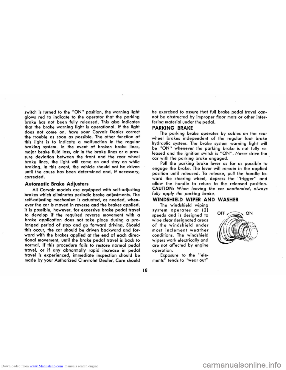
WINDSHIELD WIPER AND WASHER
The windshield wiping
system operates at (2)
speeds and is designed to
wipe clear
designated areas
of the windshield under
most inclement weather
conditions. The windshield
wipers work
electrically and
are not affected by engine
operation.
Exposure to the "ele
ments" tends to "wear out"
OFF~ON
Page 41 of 56
Downloaded from www.Manualslib.com manuals search engine Also, all hoses, fittings and the inlet air filter should be
inspected, cleaned and replciced if necessary.
NOTE: If the positive crankcase ventilator valve should
become
dogged, the engine idle will be adversely
affect~d. Therefore, if the engine idle becomes too slow
or rough, the ventilator valve should be checked before
any carburetor ad;ustments are made to compensate for
the trouble.
AIR INJECTION REACTOR (A.I.R.l
The Air
Injection Reactor system is designed to re
duce .air pollution caused by exhaust emissions. It is entirely separate from the Positive Crankcase Ventilating
system. The Air
Injection Reactor system operates by
oxidizing (or burning) the
hydrocarbons and carbon
monoxide as they are expelled from the combustion
chamber into the exhaust. A positive displacement air
pump, driven by the engine, compresses clean frltered
air, which
is distributed and injected at the exhaust part
of each cylinder. This fresh air mixes with the hot exhaust
gases and promotes further oxidation (or burning) of
both hydrocarbons and carbon monoxide by converting
some
of them to carbon dioxide and water. This does not
reduce the danger of inhaling carbon monoxide in con
frned areas. See page 7 for carbon monoxide warning.
Supplementing
the air pump a special carburetor and
distributor plus related components are required.
The Air
Injection Reactor system should have the A.I.R. pump filter serviced and the drive belt inspected
for
wear and tension every 12 months or 12,000 miles,
38
whichever occurs frrst. In addition, complete effectiveness
of the system, as well as full power and performance,
depends upon idle speed, ignition timing, and idle fuel
mixture being
set according to specifrcation. A quality
tune-up which includes
these adjustments should be per
formed periodically to assure normal engine efficiency,
operation and performance.
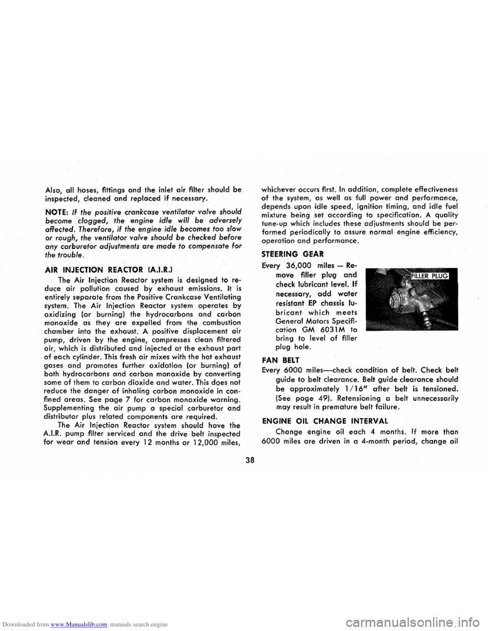
STEERING GEAR
Every 36,000 miles -Re
move frller plug and
check lubricant level. If
necessary, add water
resistant EP chassis lu
bricant which meets
General Motors Specifr
cation GM 6031 M to
bring to level
of frller
plug hole.
FAN BELT
Every 6000 miles-check condition of belt. Check belt
guide to belt clearance. Belt guide ciearance should
be approximately 1/16" after belt is tensioned.
(See page 49). Retensioning a belt unnecessarily
may result
in premature belt fciilure.
ENGINE OIL CHANGE INTERVAL
Change engine oil each 4 months. If more than
6000 miles are driven in a 4-month period, change oil