1986 CHEVROLET CORVAIR clock
[x] Cancel search: clockPage 19 of 56

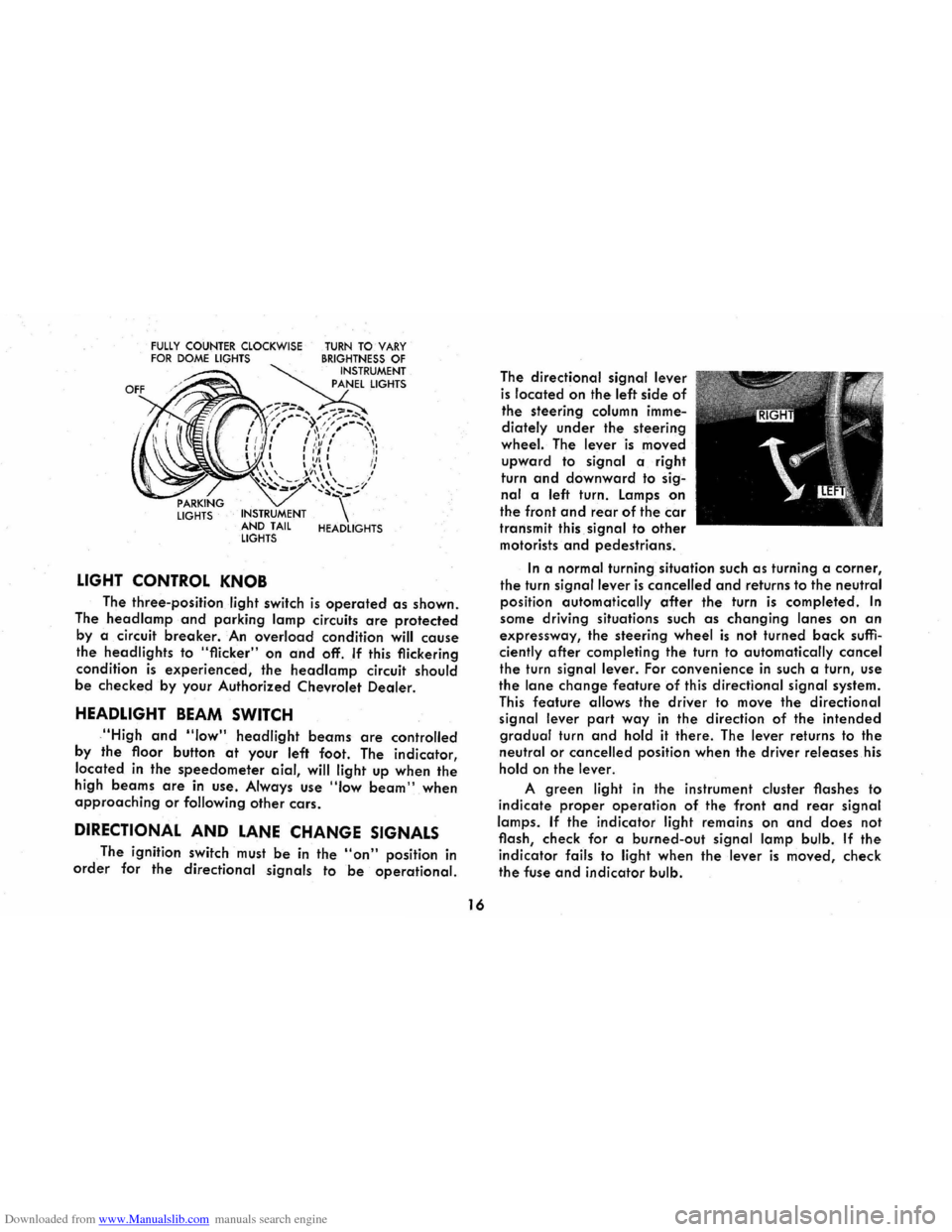
Downloaded from www.Manualslib.com manuals search engine FULLY COUNTER CLOCKWISE FOR DOME LIGHTS
LIGHTS INSTRUMENT
AND TAIL
LIGHTS
LIGHT CONTROL KNOB
TURN TO VARY BRIGHTNESS OF INSTRUMENT
PANEL LIGHTS
HEADLIGHTS
The three-position light switch is operated as shown.
The
head lamp and parking lamp circuits are protected
by a circuit breaker. An overload condition will cause
the headlights to "flicker" on and off. If this flickering
condition
is experienced, the headlamp circuit should
be checked by your Authorized Chevrolet Dealer.
HEADLIGHT BEAM SWITCH
,"High and "low" headlight beams are controlled
by
the floor button at your left foot. The indicator,
located
in the speedometer aial, will light up when the
high beams are in use . Always use "Iow beam" when approaching or following other cars.
DIRECTIONAL AND LANE CHANGE SIGNALS
The ignition switch must be in the "on" position in
order for the directional signals to be operational.
16
The directional signal lever
is located on the left side of
the steering column imme
diately
under the steering
wheel. The lever is moved
upward to signal a right
turn
and downward to sig
nal a left turn. Lamps on
the front and rear of the car
transmit this signal to other
motorists and pedestrians.
In a normal turning situation such as turning a corner,
the turn signal lever is cancelled and returns to the neutral
position automatically
after the turn is completed. In
some driving situations such as changing lanes on an
expressway, the steering wheel is not turned back suffi
ciently after completing the turn to automatically cancel
the turn signal lever. For convenience in such a turn, use
the lane change feature of this directional signal system.
This feature allows the driver to move the directional
signal lever
part way in the direction of the intended
gradual turn and hold it there. The lever returns to the
neutral or cancelled position when the driver releases his
hold on the lever.
A green light in the instrument cluster flashes to
indicate
proper operation of the front and rear signal
lamps.
If the indicator light remains on and does not
flash, check for a burned-out
signal lamp bulb. If the
indicator fails to light when the lever is moved, check
the fuse and indicator bulb.
Page 25 of 56

Downloaded from www.Manualslib.com manuals search engine AIR VENTS
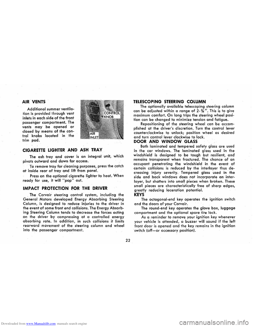
Additional summer ventila
tion is provided through vent
inlets in each side of the front
passenger compartment. The
vents
may be opened or
closed by means of the con
trol knobs located in the
trim pad.
CIGARETTE LIGHTER AND ASH TRAY
The ash tray and cover is an integral unit, which
pivots
outward and down for access.
To
remove tray for cleaning purposes, press the catch
at inside rear of tray and lift from panel.
Press on the optional cigarette lighter to heat. When
ready for use, it will "pop" out. '
IMPACT PROTECTION FOR THE DRIVER
. The Corvair steering control system, includil)g the
General Motors developed Energy Absorbing Steering
Column,
is designed to reduce injuries to the driver in
the event
of some front end collisions. The Energy Absorb
ing Steering Column tends to decrease the forces acting
on the driver by compressing at a controlled energy
absorbing rate. In addition, in such collisions it limits
rearward movement of the steering column and wheel
into the passenger compartment.
22
TELESCOPING STEERING COLUMN
The optionally available telescoping steering column
can be adjusted
within a range of 2-%". This is to give maximum comfort. On long trips the steering wheel posi
tion can
be changed to minimize tension and fatigue. Repositioning of the steering wheel can be accom
plished
at the driver's discretion. Turn the control lever
counterclockwise to unlock; position wheel as desired
and turn control lever clockwise to lock.
DOOR AND WINDOW GLASS
Both laminated and tempered safety glass are used
in the
car windows. The laminated glass used in the windshield is designed to be tough but resilient, and
remains transparent when fractured. The chance of an
occupant penetrating the windshield in the event of
certain collisions is reduced by the interlayer thus de
creasing injury severity. Tempered glass used in the
side
and back windows does not incorporate an inter
layer, but shatters into small pieces when broken. These
small pieces
are characteristically free of sharp edges,
greatly reducing laceration potential.
KEYS
The octagonal-end key operates the ignition switch
and the doors of your Corvair.
The round-end key operates the glove box, luggage
compartment and the optional spare tire lock.
As a
reminder to remove your ignition key whenever
your vehicle is attended, a buzzer will sound if the left
front door is opened and the key remains in the ignition
switch (off-or accessory position).
Page 32 of 56

Downloaded from www.Manualslib.com manuals search engine inches to assure that the lid lock mechanism is en
gaged.
For proper engine cooling keep the vents located
below the
rear window free of ice, snow and leaves.
LUGGAGE COMPARTMENT
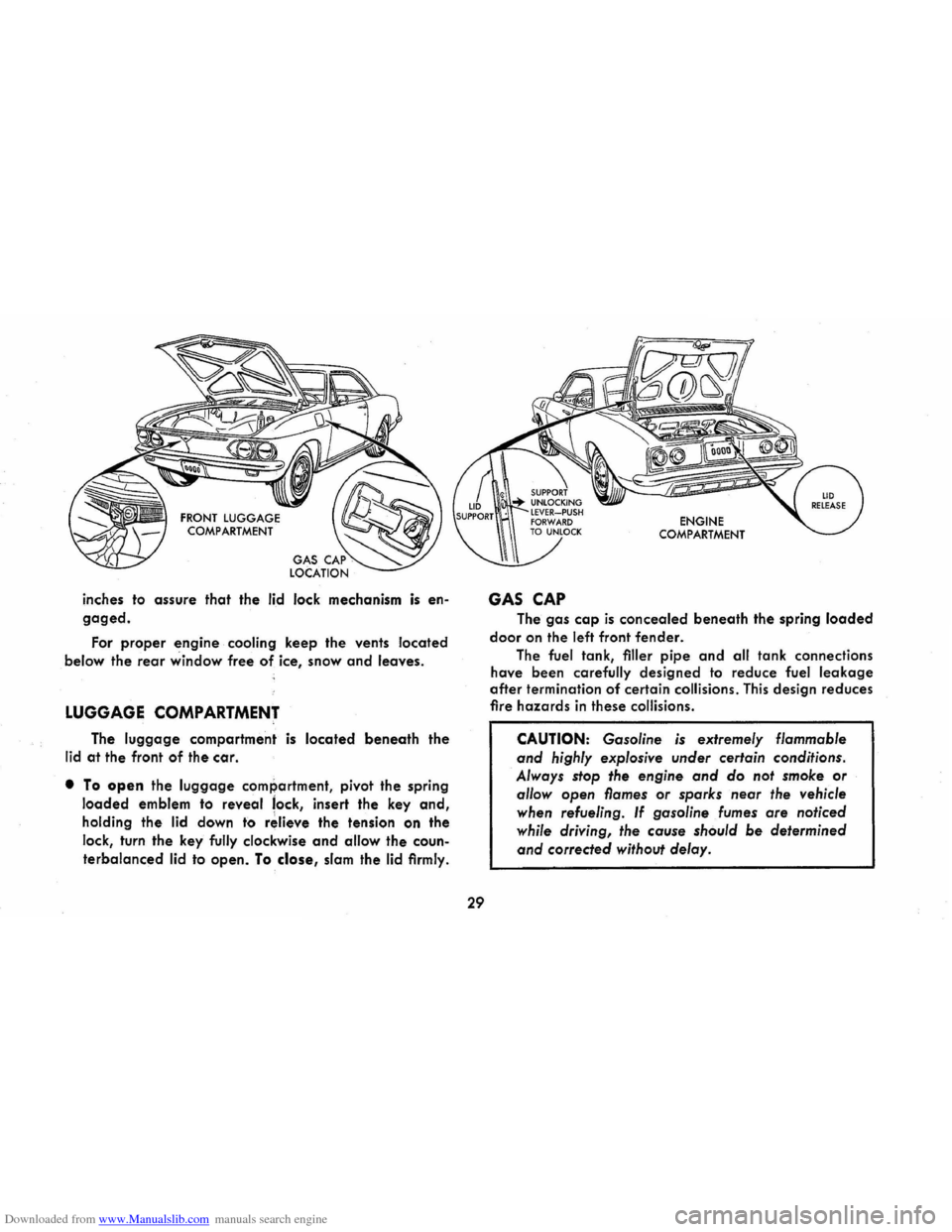
The luggage compartment is located beneath the
lid at the front of the car.
• To open the luggage compartment, pivot the spring
loaded emblem to reveal lock, insert the key and,
holding the lid down to r~lieve the tension on the
lock, turn the key fully clockwise
and allow the coun
terbalanced lid to open. To close, slam the lid firmly.
29
GAS CAP
ENGINE COMPARTMENT
The gas cap is concealed beneath the spring loaded
door on the left front fender.
The fuel tank, filler pipe and all tank connections
have been carefully designed to reduce fuel
leakage
after termination of certain collisions. This design reduces
fire hazards in these collisions.
CAUTION: Gasoline is extremely flammable
and highly explosive under certain conditions.
Always stop the engine
and do not smoke or
allow open flames or sparks near the vehicle
when refueling.
If gasoline fumes are noticed
while driving,
the cause should be determined
and corrected without delay.
Page 48 of 56

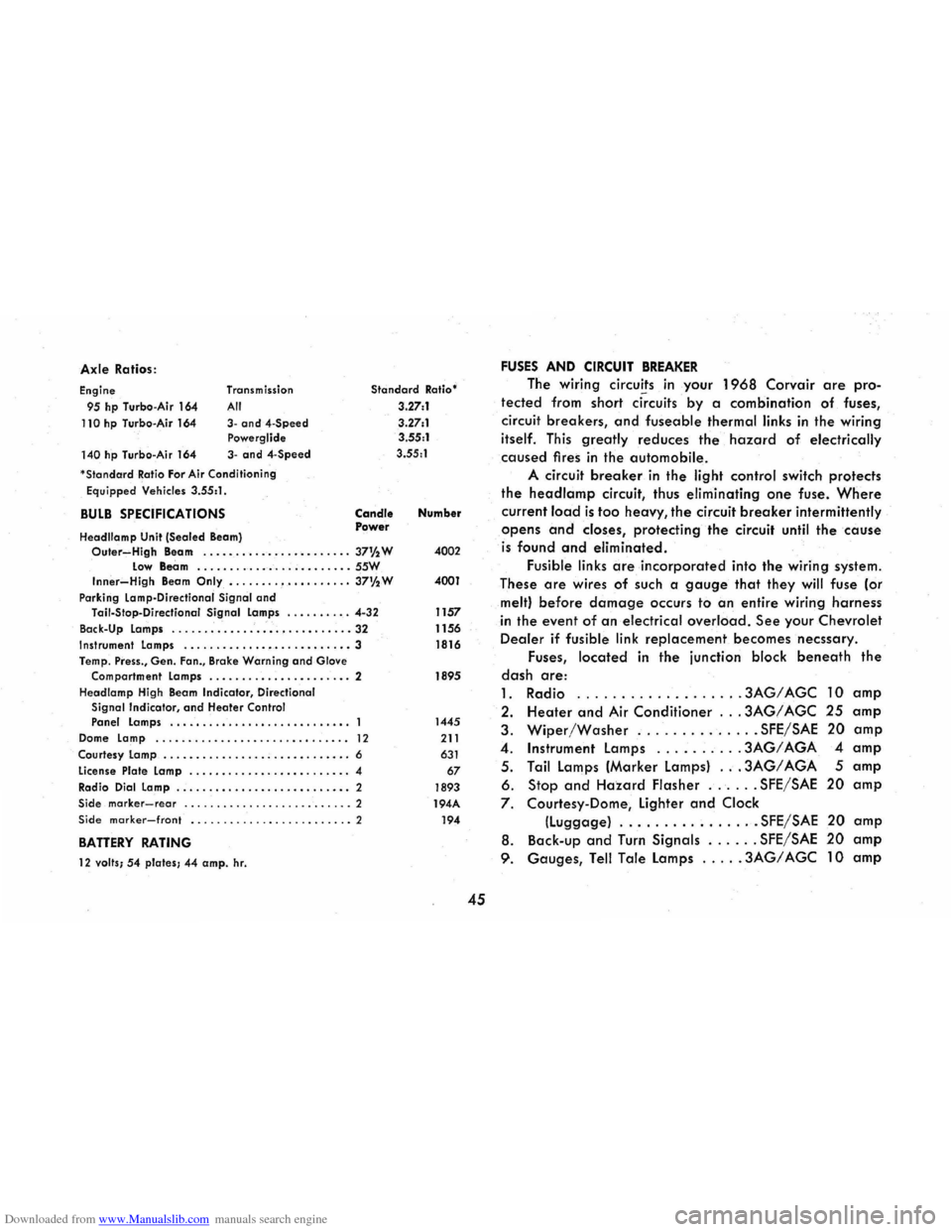
Downloaded from www.Manualslib.com manuals search engine Axle Ratios :
Engine
95 hp Turbo -Air 164
110 hp Turbo-Air 164
140 hp Turbo -Air 164 Transm
ission
All
3-and4-Speed Powerglide
3-and 4-Speed
'
StandardRatio For Air Cond itioning
Equipped Vehicles 3.55:1 .
BULB SPECIFICATIONS
Headllamp Unit (Sealed Beam)
Standard Ratio'
3.27:1
3 .27:1
3.55:1
3.55 :1
Candle Power Number
Outer~High Beam . .....•...•...•........ 37% W 4002 Low Beam .......... _ ....... _ .. _ .. SSW Inner-High Beam Only •....... , •.•. •.•... 37%W 4001
Park ing Lamp-Directional Signal and Tail-Stop -Directianal Signal Lamps ........ . . 4-32 1157
Back-Up Lamps
............................ 32 1156 Instrument Lamps ........ _ ...•••.....•....• 3 1816
Temp . Press., Gen. Fan., Brake Warning and Glove
Compartment Lamps ...........•... ..•..• . 2 1895
Headlamp High Beam
Indicator , Directional Signal Indicator, and Heater Control Panel Lamps ................•......•.•.. 1445
Dome Lamp ........................... ..• 12 211
Courtesy Lamp ............... . ; ....•..••... 6 631
License Plate Lamp ..............• •......... 4 67
Radio Dial Lamp .....................•..• " 2 1893 Side marker-rear .......................... 2 194A Side marker-front ......................... 2 194
BATTERY RATING
12 valls; 54 plates; 44 amp. hr.
45
FUSES AND CIRCUIT BREAKER
The wiring circuits in your 1968 Corvair are pro
tected from short ci~cuits by a combination of fuses,
circuit
breakers, and fuseable thermal links in the wiring
itself. This greatly reduces the hazard of electrically
caused fires in the automobile.
A circuit breaker in the light control switch protects
the headlamp circuit, thus eliminating one fuse. Where
current lo.ad is too heavy, the circuit breaker intermittently
opens and closes, protecting the circuit until the cause
is found and eliminated.
Fusible links are incorporated into the wiring system.
These
are wires of such a gauge that they will fuse (or
melt) before damage occurs to an entire wiring harness
in the event of an electrical overload. See your Chevrolet
Dealer if fusible link replacement becomes necssary.
Fuses,
located in the junction block beneath the
dash are:
1. Radio .
........ ...... .. , .3AG/AGC 10 amp
2. Heater and Air Conditioner ... 3AG/ AGC 25 amp
3. Wiper/Washer .............. SFE/SAE 20 amp
4 . Instrument lamps ......... . 3AG/ AGA 4 amp
5 . Tail lamps (Marker lamps) ... 3AG/ AGA 5 amp
6. Stop and Hazard Flasher ...... SFE/SAE 20 amp
7. Courtesy-Dome, lighter and Clock
(luggage) ................ SFE/SAE 20 amp
8. Back -up and Turn Signals ...... SFE/SAE 20 amp
9. Gauges, Tell Tale lamps ..... 3AG/ AGC 10 amp