Page 563 of 885

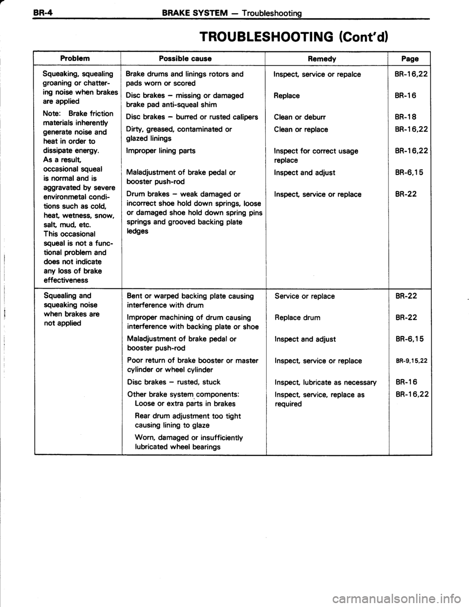
BR-4 BRAKE SYSTEM - Troubleshooting
TROU BLESHOOTI NG (Cont'd)
ProblemPossible causeRemedyPage
Squeaking, squealing
groaning or chatter-
ing noise when brakes
are applied
Note: Brake friction
materials inherently
generate noise and
heat in order to
dissipate energy.
As a result
occasional squeal
is normaland is
aggravated by severe
environmetal condi-
tions such as cold,
heat, wetness, snow,
salt mud, etc.
This occasional
squeal is not a func-
tional problem and
does not indicate
any loss of brake
effectiveness
Brake drums and linings rotors and
pads worn or scored
Disc brakes - missing or damaged
brake pad anti-squeal shim
Disc brakes - burred or rusted calipers
Dirty, greased, contaminated or
glazed linings
lmproper lining parts
Maladjustment of brake pedal or
booster push-rod
Drum brakes - weak damaged or
incorrect shoe hold down springs, loose
or damaged shoe hold down spring pins
springs and grooved backing plate
ledges
Inspect, service or repalce
Replace
Clean or deburr
Clean or replace
Inspect for conect usage
replace
lnspect and adjust
Inspect service or replace
BR-16,22
BR.l 6
BR-1 8
BR-16,22
BR-'�t6,22
BR-6,15
8R.22
Squealing and
squeaking noise
when brakes are
not applied
Bent or warped backing plate causing
interference with drum
lmproper machining of drum causing
interference with backing plate or shoe
Maladjustment of brake pedal or
booster push-rod
Poor return of brake booster or master
cylinder or wheel cylinder
Disc brakes - rusted, stuck
Other brake system, components:
Loose or extra parts in brakes
Rear drum adjustment too tight
causing lining to glaze
Worn, damaged or insufficiently
lubricated wheel bearings
Service or replace
Replace drum
Inspect and adjust
Inspect, service or replace
Inspect lubricate as necessary
Inspect, service, replace as
required
BR-22
8R.22
BR-6,15
BR-g,15,22
BR.1 6
BR-16,22
Page 564 of 885

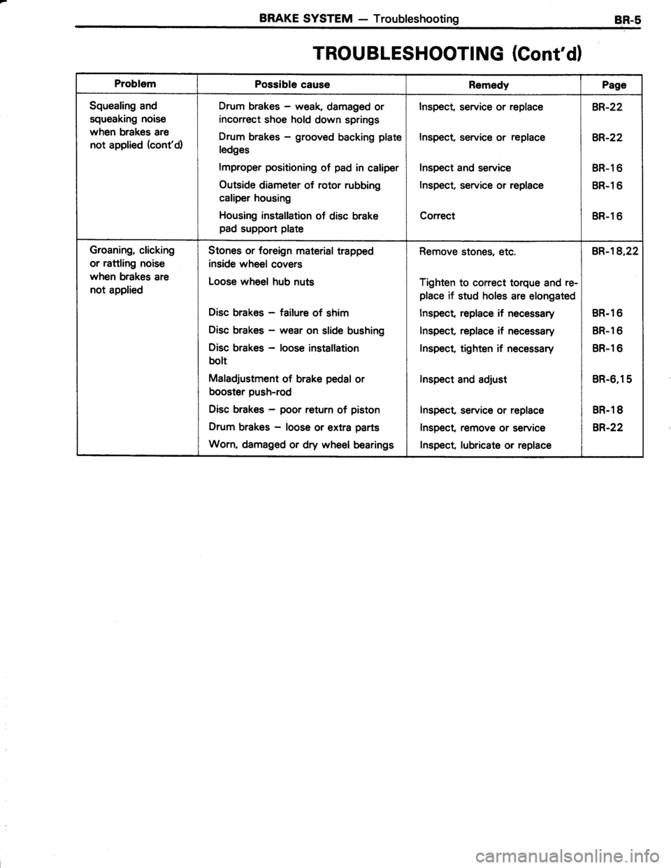
BRAKE SYSTEM - TroubleshootingBR-5
TROUBLESHOOTING (Cont'dl
ProblemPossible causeRemedyPage
Squealing and
squeaking noise
when brakes are
not applied (cont'd)
Drum brakes - weak, damaged or
incorrect shoe hold down springs
Drum brakes - grooved backing plate
ledges
lmproper positioning of pad in caliper
Outside diameter of rotor rubbing
caliper housing
Housing installation of disc brake
pad support plate
Inspect, service or replace
Inspect, service or replace
Inspect and service
Inspect, service or replace
Correct
BR-22
BR-22
BR-l 6
BR-l 6
BR-1 6
Groaning, clicking
or rattling noise
when brakes are
not applied
Stones or foreign material trapped
inside wheel covers
Loose wheel hub nuts
Disc brakes - failure of shim
Disc brakes - wear on slide bushing
Disc brakes - loose installation
bolt
Maladjustment of brake pedal or
booster push-rod
Disc brakes - poor return of piston
Drum brakes - loose or extra parts
Worn, damaged or dry wheel bearings
Remove stones, etc.
Tighten to correct torque and re-
place if stud holes are elongated
lnspect, replace if necessary
Inspect, replace if necessary
Inspect, tighten if necessary
lnspect and adjust
Inspect, service or replace
Inspect remove or service
lnspect lubricate or replace
BR-18,22
BR.1 6
BR.1 6
BR-1 6
BR-6,15
BR.1 8
B,R.22
Page 566 of 885

BRAKE SYSTEM - Checks and AdjustmentsBR-7
@@
VV
1 st 2nd
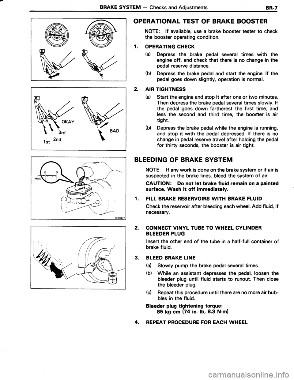
OPERATIONAL TEST OF BRAKE BOOSTER
NOTE: lf available, use a brake booster tester to check
the booster operating condition.
1. OPERATING CHECK
(a) Depress the brake pedal several times with the
engine off, and check that there is no change in the
pedal reserve distance.
(b) Depress the brake pedal and start the engine. lf the
pedal goes down slightly, operation is normal.
2. AIR TIGHTNESS
(d Start the engine and stop it after one or two minutes.
Then depress the brake pedal several times slowly. lf
the pedal goes down fartherest the first time, and
less the second and third time, the boo$ter is air
tight.
(b) Depress the brake pedal while the engine is running,
and stop it with the pedal depressed. lf there is no
change in pedal reserve travel after holding the pedal
for thirty seconds, the booster is air tight.
BLEEDING OF BRAKE SYSTEM
NOTE: lf any work is done on the brake system or if air is
suspected in the brake lines, bleed the system of air.
CAUTION: Do not let brake fluid remain on a painted
surface. Wash it off immediataly.
1. FILL BRAKE RESERVOIRS WITH BRAKE FLUID
Check the reservoir after bleeding each wheel. Add fluid, if
necessary.
2, CONNECT VINYL TUBE TO WHEEL CYLINDER
BLEEDER PLUG
lnsert the other end of the tube in a half-full container of
brake fluid.
3. BLEED BRAKE LINE
(a) Slowly pump the brake pedal several times.
(b) While an assistant depresses the pedal, loosen the
bleeder plug until fluid starts to runout. Then close
the bleeder plug.
(c) Repeat this procedure until there are no more air bub-
bles in the fluid.
Bleeder plug tightening torque:
85 kg-cm (74 in.-lb,8.3 N.m)
4. REPEAT PROCEDURE FOR EACH WHEEL
Page 573 of 885
8R.14BRAKE SYSTEM - Brake Booster
REMOVAL OF BRAKE BOOSTER
levis
II
dCI
130 (9, 131f=s(lr=' I
5
llJ
3-Way Unionl
(ft-lb, N.m):Tightening torque
0 : Non-reusable part
Brake Fluid Level Warning
Switch Connector
Brake Booster
BRAKE BOOSTER
1. REMOVE MASTER CYLINDER (See page Bn-gl
2. DISCONNECT VACUUM HOSE FROM BRAKE
BOOSTER
3. REMOVE DISTRIBUTOR CAP
4. REPEAT PROCEDURE FOR EACH WHEEL
5. REMOVE HEATER AIR DUCT
6. DISCONNECT PEDAL RETURN SPRING FROM
BRAKE PEDAL
7. DISCONNECT PUSH ROD CLEVIS FROM BRAKE
PEDAL
Remove the clip and clevis pin.
8. REMOVE BRAKE BOOSTER
Remove the four nuts, and pull out the brake booster.
Page 575 of 885
BR-l6BRAKE SYSTEM - Front Brake
FRONT BRAKE
COMPONENTS
I
IREPLACEMENT OF BRAKE PADS
. lf a squeaking noise occurs while braking, inspect the
. brake pads. Brake squeak will occur when the gap be-
tween the pad wear indicator plate and rotor disc reaches
about 2.5 mm (0.098 in.).
1. REMOVE FRONT WHEET
Rqmove the wheel and temporarily fasten the rotdfu discwith the wheel nuts. ;:E "'
2. INSPECT PAD LINING THICKNESS
Check the pad thickness through the cylinder inspection' hole and replace pads if not within specification.
Standard
Minimum
1O.0 mm (0.394-in.l
1.0 mm (0.039 in.)
\_ [-5s ntzst IFlexible Hose--\\>.;lco
Ja-- |I 'r fa-l
235 117,231
900 165,88)j Torque Plate
Leh
A\H)
Rotor Disc
Anti-squeal shim __Anti-squeal
I Spring
-cm (ft-lb, N.m)
8ao?36
Page 577 of 885

BR-l8BRAKE SYSTEM - Front Brake
'- t.t
d[
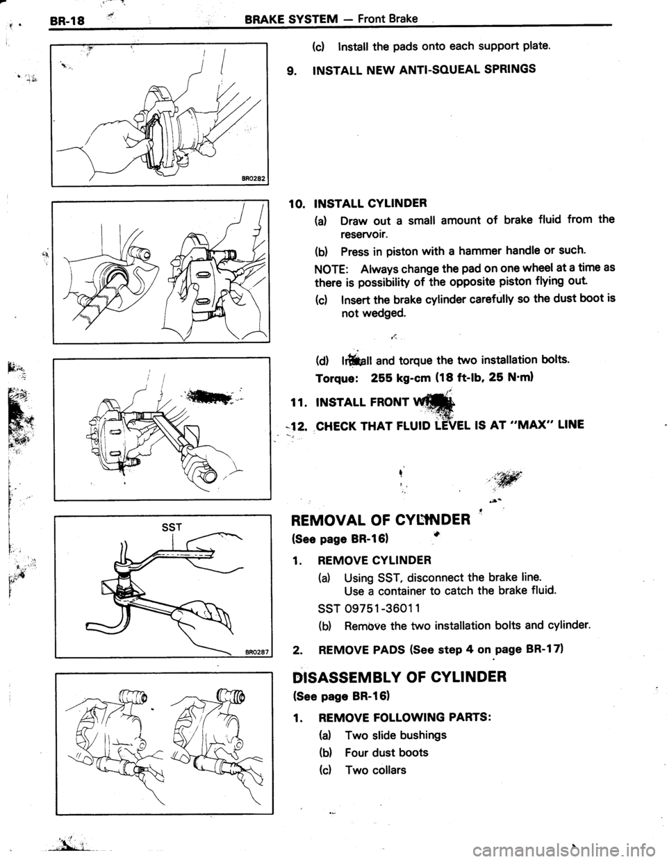
(c! Install the pads onto each support plate'
9. INSTALL NEW ANTI-SOUEAL SPRINGS
10. INSTALL CYLINDER
(d Draw out a small amount of brake fluid from the
reservoir.
(b) Press in piston with a hammer handle or such.
NOTE: Always change the pad on one wheel at a time as
there is possibility of the opposite piston flying out
(c) Insert the brake cylinder carefully so the dust boot is
not wedged.
t1.,
(d) lrfiiprr and torque the two instatlation bolts.
Torque: 255 kg-cm (18 ft-lb, 25 N'ml
t t. tNsrArL FRoNr Itr#
*12. CHECK THAT FLUID TEVEL IS AT "MAX" LINE
I,iw,i
REMOVAL OF CYUTNDER '
(See page BR-l61
1. REMOVE CYLINDER
(a) Using SST, disconnect the brake line.
Use a container to catch the brake fluid.
ssT 09751 -3601 1
(b) Rembve the two installation bolts and cylinder.
2. REMOVE PADS (See step 4 on.page BR-l71
DISASSEMBLY OF CYLINDER
(See page BR-l61
1. REMOVE FOLLOWING PARTS:
(a) Two slide bushings
(b) Four dust boots
(d Two collars
I'idr
SST
"'L i-
Page 579 of 885
BR-2OBRAKE SYSTEM - Front Brake
3. INSPECT ROTOR DISC RUNOUT
Measure the rotor disc runout at 1O mm (0.39 in.) from the
outer edge of the rotor disc.
Maximum disc runout: 0.15 mm (0.0059 in.l
lf the runout is greater than maximum, replace the disc.
NorE: Before measuring the runout check that the front
bearing play is within specification.
4. IF NECESSARY, REPLACE ROTOR DISC
(d Remove the torque plate from the knuckle.
(b) Remove the wheel nuts of the temporarily installed
disc and pull off the rotor disc from the axle hub.
(c) Temporarily install a new rotor disc with the wheel
nuts.
(d) Install the torque plate onto the knuckle.
Torque: 900 kg-cm (65 ft-lb, 88 N'm)
ASSEMBLY OF CYLINDER
(See page BR-161
1. APPLY LITHUM SOAP BASE GLYCOL GREASE
TO PARTS INDICATED BY ARROWS
2. INSTALL PISTON SEAL AND PISTON IN CYLINDER
INSTALL CYLINDER BOOT AND SET RING IN
CYLINDER
\
ti
3.
Q++, i,
Page 581 of 885
BR-22BRAKE SYSTEM - Rear Brake (Sedan)
REAR BRAKE
Sedan
COMPONENTS
Backing Plate
Shoe
Adjusting Shim
O C-Washer
Adjusting Lever
Spring
Return Spring
ob@
lGc.l?t-lb' Nrdl : Tishtenins
O: Non-reusable part
REMOVAL OF REAR BRAKE
1. INSPECT SHOE LINING THICKNESS
Remove the inspection hole plug, and check the shoe lin-
ing thickness through the hole.
lf less than minimum, replace the shoes.
Standard thickness: 4.0 mm (0.157 in.l
Minimum thickness: 1.0 mm (O.039 in.l
2. REMOVE REAR WHEEL
3. REMOVE BRAKE DRUM
(See step 2 on page RA-51
lf the brake drum cannot be easily removed, do the follow-
ing procedure:
(d Insert a screwdriver through the hole in the backing
plate, and hold the automatic adjusting lever away
from the adjusting bolt
(b) Using another screwdriver, reduce the brake shoe
adjustment by turning the adiusting bolt.