1985 FORD GRANADA ECO mode
[x] Cancel search: ECO modePage 111 of 255
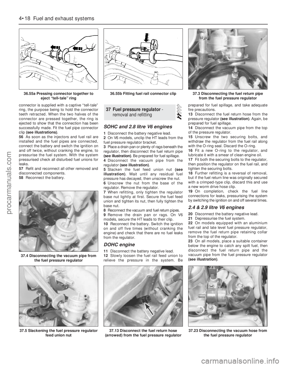
connector is supplied with a captive “tell-tale”
ring, the purpose being to hold the connector
teeth retracted. When the two halves of the
connector are pressed together, the ring is
ejected to show that the connection has been
successfully made. Fit the fuel pipe connector
clip (see illustrations).
56As soon as the injectors and fuel rail are
installed and the fuel pipes are connected,
connect the battery and switch the ignition on
and off twice, without cranking the engine, to
pressurise the fuel system. With the system
pressurised check all disturbed fuel unions for
leaks.
57Refit and reconnect all other removed and
disconnected components.
58Reconnect the battery.
SOHC and 2.8 litre V6 engines
1Disconnect the battery negative lead.
2On V6 models, unclip the HT leads from the
fuel pressure regulator bracket.
3Place a drain pan or plenty of rags beneath the
regulator, then disconnect the fuel return pipe
(see illustration). Be prepared for fuel spillage.
4Disconnect the vacuum pipe from the
regulator (see illustration).
5Slacken the fuel feed union nut (see
illustration). Wait until any residual fuel
pressure has decayed, then unscrew the nut.
6Unscrew the nut from the base of the
regulator. Remove the regulator.
7When refitting, only tighten the regulator
base nut lightly at first. Secure the fuel feed
union and tighten its nut, then fully tighten the
base nut.
8Reconnect the vacuum and fuel return pipes.
9Remove the drain pan or rags. On V6
models, secure the HT leads to their clip.
10Reconnect the battery. Switch the ignition
on and off five times (without cranking the
engine) and check that there are no fuel leaks
from the regulator.
DOHC engine
11Disconnect the battery negative lead.
12Slowly loosen the fuel rail feed union to
relieve the pressure in the system. Beprepared for fuel spillage, and take adequate
fire precautions.
13Disconnect the fuel return hose from the
pressure regulator (see illustration). Again, be
prepared for fuel spillage.
14Disconnect the vacuum pipe from the top
of the pressure regulator.
15Unscrew the two securing bolts, and
withdraw the regulator from the fuel rail along
with the O-ring seal. Discard the O-ring.
16Fit a new O-ring to the regulator, and
lubricate it with a smear of clean engine oil.
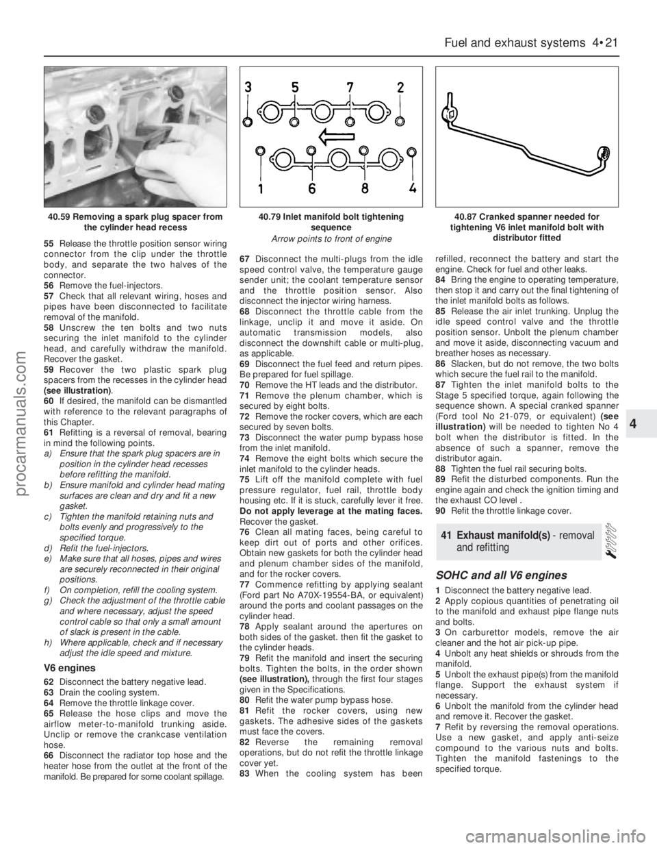
17Fit both the securing bolts to the regulator,
then position the regulator on the fuel rail, and
tighten the securing bolts.
18Further refitting is a reversal of removal,
but if the fuel return line was originally secured
with a crimped-type clip, discard this and use
a new worm drive hose clip.
19On completion, check the fuel line
connections for leaks, pressurising the system
by switching the ignition on and off several times.
2.4 & 2.9 litre V6 engines
20Disconnect the battery negative lead.
21Depressurise the fuel system.
22On models equipped with an aluminium
fuel rail and late level fuel pressure regulator,
remove the fuel return pipe retaining collar
from the top of the regulator.
23On all models, place a suitable container
below the engine to catch any spilt fuel, then
disconnect the fuel return pipe and the
vacuum pipe from the fuel pressure regulator
(see illustration).
37Fuel pressure regulator -
removal and refitting
4•18Fuel and exhaust systems
36.55a Pressing connector together to
eject “tell-tale” ring
37.4 Disconnecting the vacuum pipe from
the fuel pressure regulator
37.5 Slackening the fuel pressure regulator
feed union nut37.13 Disconnect the fuel return hose
(arrowed) from the fuel pressure regulator37.23 Disconnecting the vacuum hose from
the fuel pressure regulator
36.55b Fitting fuel rail connector clip37.3 Disconnecting the fuel return pipe
from the fuel pressure regulator
procarmanuals.com
Page 112 of 255
24Unbolt and remove the regulator from the
fuel rail. Remove the sealing O-ring and
discard it; a new one must be used on
refitting.
25Refitting is a reverse of the removal
procedure applying a smear of clean engine oil
to the new regulator O-ring. On models
equipped with a late level regulator, ensure
that the return pipe is securely held in position
by the retaining collar.
26On completion, switch the ignition on and
off five times without cranking the engine to
pressurise the fuel system.
27With the system pressurised check all
disturbed fuel unions for signs of leakage.
1The potentiometer is located on the right-
hand side of the engine compartment, behind
the MAP sensor.
2Disconnect the battery negative lead.
3Remove the securing screw, then withdraw
the potentiometer and disconnect the wiring
plug.
4Refitting is a reversal of removal. On
completion adjust the idle mixture.1On 2.4 & 2.9 litre V6 engines, disconnect the
battery.
2Disconnect the switch wiring connector.
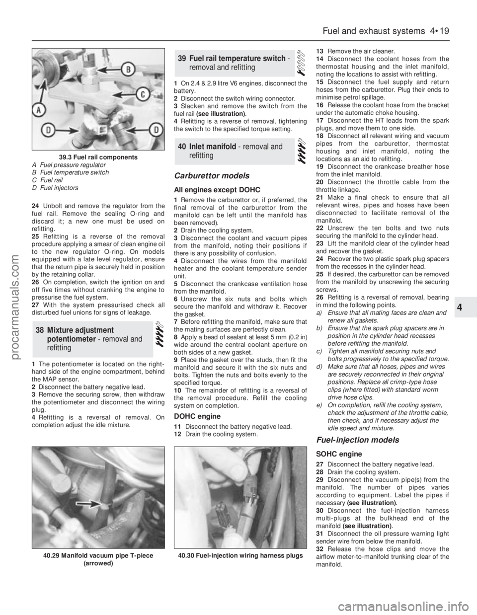
3Slacken and remove the switch from the
fuel rail (see illustration).
4Refitting is a reverse of removal, tightening
the switch to the specified torque setting.
Carburettor models
All engines except DOHC
1Remove the carburettor or, if preferred, the
final removal of the carburettor from the
manifold can be left until the manifold has
been removed).
2Drain the cooling system.
3Disconnect the coolant and vacuum pipes
from the manifold, noting their positions if
there is any possibility of confusion.
4Disconnect the wires from the manifold
heater and the coolant temperature sender
unit.
5Disconnect the crankcase ventilation hose
from the manifold.
6Unscrew the six nuts and bolts which
secure the manifold and withdraw it. Recover
the gasket.
7Before refitting the manifold, make sure that
the mating surfaces are perfectly clean.
8Apply a bead of sealant at least 5 mm (0.2 in)
wide around the central coolant aperture on
both sides of a new gasket.
9Place the gasket over the studs, then fit the
manifold and secure it with the six nuts and
bolts. Tighten the nuts and bolts evenly to the
specified torque.
10The remainder of refitting is a reversal of
the removal procedure. Refill the cooling
system on completion.
DOHC engine
11Disconnect the battery negative lead.
12Drain the cooling system.13Remove the air cleaner.
14Disconnect the coolant hoses from the
thermostat housing and the inlet manifold,
noting the locations to assist with refitting.
15Disconnect the fuel supply and return
hoses from the carburettor. Plug their ends to
minimise petrol spillage.
16Release the coolant hose from the bracket
under the automatic choke housing.
17Disconnect the HT leads from the spark
plugs, and move them to one side.
18Disconnect all relevant wiring and vacuum
pipes from the carburettor, thermostat
housing and inlet manifold, noting the
locations as an aid to refitting.
19Disconnect the crankcase breather hose
from the inlet manifold.
20Disconnect the throttle cable from the
throttle linkage.
21Make a final check to ensure that all
relevant wires, pipes and hoses have been
disconnected to facilitate removal of the
manifold.
22Unscrew the ten bolts and two nuts
securing the manifold to the cylinder head.
23Lift the manifold clear of the cylinder head
and recover the gasket.
24Recover the two plastic spark plug spacers
from the recesses in the cylinder head.
25If desired, the carburettor can be removed
from the manifold by unscrewing the securing
screws.
26Refitting is a reversal of removal, bearing
in mind the following points.
a)Ensure that all mating faces are clean and
renew all gaskets.
b)Ensure that the spark plug spacers are in
position in the cylinder head recesses
before refitting the manifold.
c)Tighten all manifold securing nuts and
bolts progressively to the specified torque.
d)Make sure that all hoses, pipes and wires
are securely reconnected in their original
positions. Replace all crimp-type hose
clips (where fitted) with standard worm
drive hose clips.
e)On completion, refill the cooling system,
check the adjustment of the throttle cable,
then check, and if necessary adjust the
idle speed and mixture.
Fuel-injection models
SOHC engine
27Disconnect the battery negative lead.
28Drain the cooling system.
29Disconnect the vacuum pipe(s) from the
manifold. The number of pipes varies
according to equipment. Label the pipes if
necessary (see illustration).
30Disconnect the fuel-injection harness
multi-plugs at the bulkhead end of the
manifold (see illustration).
31Disconnect the oil pressure warning light
sender wire from below the manifold.
32Release the hose clips and move the
airflow meter-to-manifold trunking clear of the
manifold.
40Inlet manifold - removal and
refitting
39Fuel rail temperature switch -
removal and refitting
38Mixture adjustment
potentiometer - removal and
refitting
Fuel and exhaust systems 4•19
4
39.3 Fuel rail components
A Fuel pressure regulator
B Fuel temperature switch
C Fuel rail
D Fuel injectors
40.29 Manifold vacuum pipe T-piece
(arrowed)40.30 Fuel-injection wiring harness plugs
procarmanuals.com
Page 114 of 255
55Release the throttle position sensor wiring
connector from the clip under the throttle
body, and separate the two halves of the
connector.
56Remove the fuel-injectors.
57Check that all relevant wiring, hoses and
pipes have been disconnected to facilitate
removal of the manifold.
58Unscrew the ten bolts and two nuts
securing the inlet manifold to the cylinder
head, and carefully withdraw the manifold.
Recover the gasket.
59Recover the two plastic spark plug
spacers from the recesses in the cylinder head
(see illustration).
60If desired, the manifold can be dismantled
with reference to the relevant paragraphs of
this Chapter.
61Refitting is a reversal of removal, bearing
in mind the following points.
a)Ensure that the spark plug spacers are in
position in the cylinder head recesses
before refitting the manifold.
b)Ensure manifold and cylinder head mating
surfaces are clean and dry and fit a new
gasket.
c)Tighten the manifold retaining nuts and
bolts evenly and progressively to the
specified torque.
d)Refit the fuel-injectors.
e)Make sure that all hoses, pipes and wires
are securely reconnected in their original
positions.
f)On completion, refill the cooling system.
g)Check the adjustment of the throttle cable
and where necessary, adjust the speed
control cable so that only a small amount
of slack is present in the cable.
h)Where applicable, check and if necessary
adjust the idle speed and mixture.
V6 engines
62Disconnect the battery negative lead.
63Drain the cooling system.
64Remove the throttle linkage cover.
65Release the hose clips and move the
airflow meter-to-manifold trunking aside.
Unclip or remove the crankcase ventilation
hose.
66Disconnect the radiator top hose and the
heater hose from the outlet at the front of the
manifold. Be prepared for some coolant spillage.67Disconnect the multi-plugs from the idle
speed control valve, the temperature gauge
sender unit; the coolant temperature sensor
and the throttle position sensor. Also
disconnect the injector wiring harness.
68Disconnect the throttle cable from the
linkage, unclip it and move it aside. On
automatic transmission models, also
disconnect the downshift cable or multi-plug,
as applicable.
69Disconnect the fuel feed and return pipes.
Be prepared for fuel spillage.
70Remove the HT leads and the distributor.
71Remove the plenum chamber, which is
secured by eight bolts.
72Remove the rocker covers, which are each
secured by seven bolts.
73Disconnect the water pump bypass hose
from the inlet manifold.
74Remove the eight bolts which secure the
inlet manifold to the cylinder heads.
75Lift off the manifold complete with fuel
pressure regulator, fuel rail, throttle body
housing etc. If it is stuck, carefully lever it free.
Do not apply leverage at the mating faces.
Recover the gasket.
76Clean all mating faces, being careful to
keep dirt out of ports and other orifices.
Obtain new gaskets for both the cylinder head
and plenum chamber sides of the manifold,
and for the rocker covers.
77Commence refitting by applying sealant
(Ford part No A70X-19554-BA, or equivalent)
around the ports and coolant passages on the
cylinder head.
78Apply sealant around the apertures on
both sides of the gasket. then fit the gasket to
the cylinder heads.
79Refit the manifold and insert the securing
bolts. Tighten the bolts, in the order shown
(see illustration),through the first four stages
given in the Specifications.
80Refit the water pump bypass hose.
81Refit the rocker covers, using new
gaskets. The adhesive sides of the gaskets
must face the covers.
82Reverse the remaining removal
operations, but do not refit the throttle linkage
cover yet.
83When the cooling system has beenrefilled, reconnect the battery and start the
engine. Check for fuel and other leaks.
84Bring the engine to operating temperature,
then stop it and carry out the final tightening of
the inlet manifold bolts as follows.
85Release the air inlet trunking. Unplug the
idle speed control valve and the throttle
position sensor. Unbolt the plenum chamber
and move it aside, disconnecting vacuum and
breather hoses as necessary.
86Slacken, but do not remove, the two bolts
which secure the fuel rail to the manifold.
87Tighten the inlet manifold bolts to the
Stage 5 specified torque, again following the
sequence shown. A special cranked spanner
(Ford tool No 21-079, or equivalent)(see
illustration)will be needed to tighten No 4
bolt when the distributor is fitted. In the
absence of such a spanner, remove the
distributor again.
88Tighten the fuel rail securing bolts.
89Refit the disturbed components. Run the
engine again and check the ignition timing and
the exhaust CO level .
90Refit the throttle linkage cover.
SOHC and all V6 engines
1Disconnect the battery negative lead.
2Apply copious quantities of penetrating oil
to the manifold and exhaust pipe flange nuts
and bolts.
3On carburettor models, remove the air
cleaner and the hot air pick-up pipe.
4Unbolt any heat shields or shrouds from the
manifold.
5Unbolt the exhaust pipe(s) from the manifold
flange. Support the exhaust system if
necessary.
6Unbolt the manifold from the cylinder head
and remove it. Recover the gasket.
7Refit by reversing the removal operations.
Use a new gasket, and apply anti-seize
compound to the various nuts and bolts.
Tighten the manifold fastenings to the
specified torque.
41Exhaust manifold(s) - removal
and refitting
Fuel and exhaust systems 4•21
4
40.59 Removing a spark plug spacer from
the cylinder head recess40.79 Inlet manifold bolt tightening
sequence
Arrow points to front of engine40.87 Cranked spanner needed for
tightening V6 inlet manifold bolt with
distributor fitted
procarmanuals.com
Page 115 of 255
DOHC carburettor engine
8This procedure is essentially as described
above, noting the following points:
a)Note the plastic bush which is fitted to the
rear manifold stud. This must be removed
before the gasket can be withdrawn.
b)On refitting ensure that the mating
surfaces are clean and dry and fit new
gaskets.
c)Apply a thin coat of anti-seize compound
to the manifold studs to aid future
removal.
d)Tighten the manifold nuts to the specified
torque settings.
DOHC fuel-injection engine
9Disconnect the battery negative lead.
10Disconnect the wiring plug from the idle
speed control valve at the front of the plenum
chamber.
11Loosen the clamp, and detach the air inlet
hose from the air inlet tubing.
12Unscrew the securing nut, and release the
air inlet tube from the bracket on the engine
compartment front panel.
13Release the air cleaner lid securing clips,
then lift away the air inlet tube, plenum
chamber and air cleaner lid as an assembly,
disconnecting the breather hose from the air
inlet tube.
14On models fitted with a catalytic
converter, disconnect the exhaust gas oxygen
sensor wiring plug.
15Unscrew the securing nuts and disconnect
the exhaust downpipe from the manifold.
Recover the gasket. Support the exhaust
downpipe from underneath the vehicle (eg
with an axle stand) to avoid placing
unnecessary strain on the exhaust system.
16Unscrew the six securing nuts, and lift the
manifold from the cylinder head. Recover the
gasket.
17Refitting is a reversal of removal, bearing
in mind the following points.
a)Ensure that all mating faces are clean, and
use a new gasket.
b)Tighten the manifold securing nuts and
the downpipe securing nuts progressively
to the specified torque (where given).
SOHC and 2.8 litre V6 engines
1Periodically inspect the exhaust system for
freedom from corrosion and security of
mountings. Large holes will be obvious; small
holes may be found more easily by letting the
engine idle and partly obstructing the tailpipe
with a wad of cloth.
2Check the condition of the rubber
mountings by applying downward pressure on
the exhaust system and observing the
mountings for splits or cracks. Renew
deteriorated mountings.
3The exhaust systems fitted in production
have fewer sections than those available for
repair. Repair sections may be fitted to
production systems by cutting at the
appropriate point.
4The production exhaust systems are made
of aluminised and stainless steel. Repair
systems are available to the same standard, or
in standard quality (SQ) painted mild steel.
5It is recommended that the whole exhaust
system be removed even if only part requires
renewal, since separation of old joints, cutting
pipes etc is much easier away from the
vehicle. Proceed as follows.
6Disconnect the battery negative lead. Raise
and support the vehicle.
7Unbolt the manifold-to-downpipe flanged
joint(s).
8On V6 models, unbolt the left-hand front
silencer mounting.
9Release any earth straps.
10With the help of an assistant, unhook the
system from its mountings and remove it.
11Renew sections as necessary. Apply
exhaust jointing compound to sliding and
flanged joints, but do not tighten their clamps
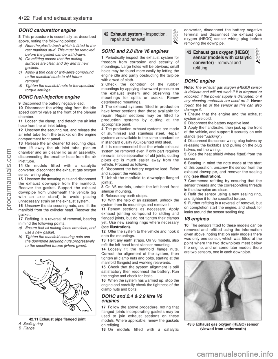
yet. Use new sealing rings where necessary
(see illustration).
12Offer the system to the vehicle and hook it
onto the mountings.
13Refit any earth straps. On V6 models, also
refit the left-hand front silencer mounting.
14Loosely fit the manifold flange nuts.
Correct the alignment of the system, then
tighten all clamp nuts and bolts, starting at the
manifold flange(s) and working rearwards.
15Check that the system alignment is still
satisfactory then reconnect the battery. Run
the engine and check for leaks.
16When the system has warmed up, stop the
engine and carefully check the tightness of the
clamp nuts and bolts.
DOHC and 2.4 & 2.9 litre V6
engines
17Follow the above procedure, noting that
flanged joints incorporating gaskets may be
used to join exhaust sections on these
models. Where applicable, renew the gaskets
on refitting.
18On models fitted with a catalyticconverter, disconnect the battery negative
terminal and disconnect the exhaust gas
oxygen (HEGO) sensor wiring plug before
removing the downpipe.
DOHC engine
Note: The exhaust gas oxygen (HEGO) sensor
is delicate and will not work if it is dropped or
knocked, if the power supply is disrupted, or if
any cleaning materials are used on it. Never
touch the tip of the sensor as this can also
damage it.
1Ensure that the engine and the exhaust
system are cold.
2Disconnect the battery negative lead.
3Apply the handbrake, then jack up the front
of the vehicle, and support it securely on axle
stands (see “Jacking”).
4Disconnect the sensor wiring plug halves by
releasing the locktabs and pulling on the plug
halves, not the wiring.
5Slide the heat shield (where fitted) from the
sensor.
6Bearing in mind the note made at the start
of this operation, unscrew the sensor from the
exhaust downpipe, and recover the sealing
ring (see illustration).
7Commence refitting by ensuring that the
sensor threads and the corresponding threads
in the downpipe are clean.
8Refit the sensor using a new sealing ring,
and tighten it to the specified torque.
9Further refitting is a reversal of removal, but
on completion start the engine, and check for
leaks around the sensor sealing ring.
V6 engines
10The sensors fitted to these models can be
removed and refitted using the information
given above, noting that on early models there
was only one sensor, which was fitted at the
point where the two downpipes meet below
the engine, and on some later models there
are two sensors, one in each downpipe.
43Exhaust gas oxygen (HEGO)
sensor (models with catalytic
converter) - removal and
refitting
42Exhaust system - inspection,
repair and renewal
4•22Fuel and exhaust systems
43.6 Exhaust gas oxygen (HEGO) sensor
(viewed from underneath)
42.11 Exhaust pipe flanged joint
A Sealing ring
B Flange
procarmanuals.com
Page 116 of 255
Models up to July 1990
1The carbon canister is situated in the engine
compartment where it is mounted onto the
right-hand valance next to the suspension
strut mounting.
2To remove the canister first disconnect the
battery negative terminal. If necessary, undo
the two coolant expansion tank retaining
screws and position the tank clear of the
canister to improve access.
3Disconnect the vacuum hose from the top
of the canister.
4Slacken and remove the mounting bolt and
withdraw the canister from the engine
compartment.
5Refitting is a reverse of the removal
procedure.
Models from July 1990
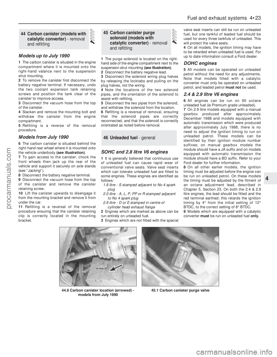
6The carbon canister is situated behind the
right-hand rear wheel where it is mounted onto
the vehicle underbody (see illustration).
7To gain access to the canister, chock the
front wheels then jack up the rear of the
vehicle and support it securely on axle stands
(see “Jacking”).
8Disconnect the battery negative terminal.
9Disconnect the vacuum hose from the top
of the canister and remove the canister
retaining screw.
10Lift the canister upwards to disengage it
from the mounting bracket and remove it from
under the car.
11Refitting is a reversal of the removal
procedure ensuring that the canister retaining
clip is correctly located in the mounting
bracket.1The purge solenoid is located on the right-
hand side of the engine compartment next to the
suspension strut mounting (see illustration).
2Disconnect the battery negative lead.
3Disconnect the solenoid wiring plug halves
by releasing the locktabs and pulling on the
plug halves, not the wiring.
4Note the locations of the two solenoid
pipes, and the orientation of the solenoid to
assist with refitting.
5Disconnect the two pipes from the solenoid,
and withdraw the solenoid from the location.
6Refitting is a reversal of removal, ensuring
that the solenoid pipes are correctly
reconnected, and that the solenoid is correctly
orientated as noted before removal.
SOHC and 2.8 litre V6 engines
1It is generally believed that continuous use
of unleaded fuel can cause rapid wear of
conventional valve seats. Valve seat inserts
which can tolerate unleaded fuel are fitted to
some engines. These engines are identified as
follows:
1.8 litre - S stamped adjacent to No 4 spark
plug
2.0 litre - A, L, P, PP or R stamped adjacent
to No 4 spark plug
2.8 litre - D or E stamped in centre of
cylinder head exhaust flange
2Engines which are marked as above can be
run entirely on unleaded fuel.
3Engines which are not fitted with the specialvalve seat inserts can still be run on unleaded
fuel, but one tankful of leaded fuel should be
used for every three tankfuls of unleaded. This
will protect the valve seats.
4On all models, the ignition timing may have
to be retarded when unleaded fuel is used. For
up to date information consult a Ford dealer.
DOHC engines
5All models can be operated on unleaded
petrol without the need for any adjustments.
Note that models fitted with a catalytic
converter must only be operated on unleaded
petrol, and leaded petrol must notbe used.
2.4 & 2.9 litre V6 engines
6All engines can be run on 95 octane
unleaded fuel (ie Premium grade unleaded).
7On 2.9 litre models equipped with a manual
gearbox produced after approximately
December 1988 and models equipped with
automatic transmission which were produced
after approximately July 1988, there is no
need to adjust the ignition timing to run on
unleaded petrol. These models can be
identified by their ignition module number
suffixes; on manual gearbox models the
module should have a JA suffix and on models
equipped with automatic transmission the
module should have a BD suffix. Refer to your
Ford dealer for further information.
8On all other earlier models, the ignition
timing must be adjusted before the engine can
be run on unleaded petrol. On these models
the timing must be adjusted by the fitment of
an octane adjustment lead, described in
Chapter 5, Section 23. On both the 2.4 & 2.9
litre engines, the lead should be fitted and the
red terminal earthed; this retards the ignition
timing by 4°from the initial setting of 12°
BTDC, to the correct setting of 8°BTDC.
9Models which are equipped with a catalytic
converter must be run on unleaded fuel only.
46Unleaded fuel - general
45Carbon canister purge
solenoid (models with
catalytic converter) - removal
and refitting44Carbon canister (models with
catalytic converter) - removal
and refitting
Fuel and exhaust systems 4•23
4
44.6 Carbon canister location (arrowed) -
models from July 199045.1 Carbon canister purge valve
procarmanuals.com
Page 119 of 255
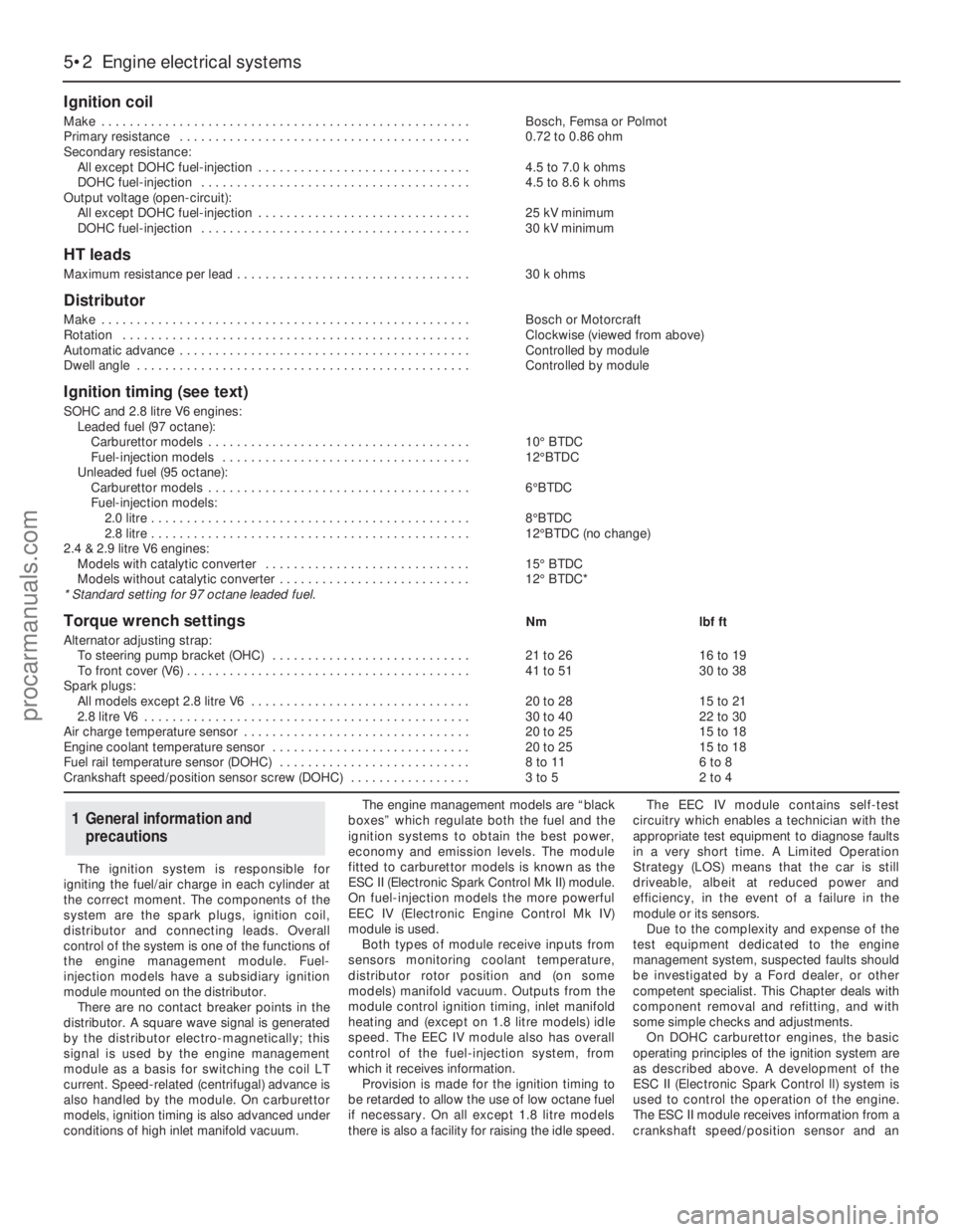
The ignition system is responsible for
igniting the fuel/air charge in each cylinder at
the correct moment. The components of the
system are the spark plugs, ignition coil,
distributor and connecting leads. Overall
control of the system is one of the functions of
the engine management module. Fuel-
injection models have a subsidiary ignition
module mounted on the distributor.
There are no contact breaker points in the
distributor. A square wave signal is generated
by the distributor electro-magnetically; this
signal is used by the engine management
module as a basis for switching the coil LT
current. Speed-related (centrifugal) advance is
also handled by the module. On carburettor
models, ignition timing is also advanced under
conditions of high inlet manifold vacuum.The engine management models are “black
boxes” which regulate both the fuel and the
ignition systems to obtain the best power,
economy and emission levels. The module
fitted to carburettor models is known as the
ESC II (Electronic Spark Control Mk II) module.
On fuel-injection models the more powerful
EEC IV (Electronic Engine Control Mk IV)
module is used.
Both types of module receive inputs from
sensors monitoring coolant temperature,
distributor rotor position and (on some
models) manifold vacuum. Outputs from the
module control ignition timing, inlet manifold
heating and (except on 1.8 litre models) idle
speed. The EEC IV module also has overall
control of the fuel-injection system, from
which it receives information.
Provision is made for the ignition timing to
be retarded to allow the use of low octane fuel
if necessary. On all except 1.8 litre models
there is also a facility for raising the idle speed.The EEC IV module contains self-test
circuitry which enables a technician with the
appropriate test equipment to diagnose faults
in a very short time. A Limited Operation
Strategy (LOS) means that the car is still
driveable, albeit at reduced power and
efficiency, in the event of a failure in the
module or its sensors.
Due to the complexity and expense of the
test equipment dedicated to the engine
management system, suspected faults should
be investigated by a Ford dealer, or other
competent specialist. This Chapter deals with
component removal and refitting, and with
some simple checks and adjustments.
On DOHC carburettor engines, the basic
operating principles of the ignition system are
as described above. A development of the
ESC II (Electronic Spark Control ll) system is
used to control the operation of the engine.
The ESC II module receives information from a
crankshaft speed/position sensor and an
1General information and
precautions
5•2Engine electrical systems
Ignition coil
Make . . . . . . . . . . . . . . . . . . . . . . . . . . . . . . . . . . . . . . . . . . . . . . . . . . . .Bosch, Femsa or Polmot
Primary resistance . . . . . . . . . . . . . . . . . . . . . . . . . . . . . . . . . . . . . . . . .0.72 to 0.86 ohm
Secondary resistance:
All except DOHC fuel-injection . . . . . . . . . . . . . . . . . . . . . . . . . . . . . .4.5 to 7.0 k ohms
DOHC fuel-injection . . . . . . . . . . . . . . . . . . . . . . . . . . . . . . . . . . . . . .4.5 to 8.6 k ohms
Output voltage (open-circuit):
All except DOHC fuel-injection . . . . . . . . . . . . . . . . . . . . . . . . . . . . . .25 kV minimum
DOHC fuel-injection . . . . . . . . . . . . . . . . . . . . . . . . . . . . . . . . . . . . . .30 kV minimum
HT leads
Maximum resistance per lead . . . . . . . . . . . . . . . . . . . . . . . . . . . . . . . . .30 k ohms
Distributor
Make . . . . . . . . . . . . . . . . . . . . . . . . . . . . . . . . . . . . . . . . . . . . . . . . . . . .Bosch or Motorcraft
Rotation . . . . . . . . . . . . . . . . . . . . . . . . . . . . . . . . . . . . . . . . . . . . . . . . .Clockwise (viewed from above)
Automatic advance . . . . . . . . . . . . . . . . . . . . . . . . . . . . . . . . . . . . . . . . .Controlled by module
Dwell angle . . . . . . . . . . . . . . . . . . . . . . . . . . . . . . . . . . . . . . . . . . . . . . .Controlled by module
Ignition timing (see text)
SOHC and 2.8 litre V6 engines:
Leaded fuel (97 octane):
Carburettor models . . . . . . . . . . . . . . . . . . . . . . . . . . . . . . . . . . . . .10°BTDC
Fuel-injection models . . . . . . . . . . . . . . . . . . . . . . . . . . . . . . . . . . .12°BTDC
Unleaded fuel (95 octane):
Carburettor models . . . . . . . . . . . . . . . . . . . . . . . . . . . . . . . . . . . . .6°BTDC
Fuel-injection models:
2.0 litre . . . . . . . . . . . . . . . . . . . . . . . . . . . . . . . . . . . . . . . . . . . . .8°BTDC
2.8 litre . . . . . . . . . . . . . . . . . . . . . . . . . . . . . . . . . . . . . . . . . . . . .12°BTDC (no change)
2.4 & 2.9 litre V6 engines:
Models with catalytic converter . . . . . . . . . . . . . . . . . . . . . . . . . . . . .15°BTDC
Models without catalytic converter . . . . . . . . . . . . . . . . . . . . . . . . . . .12°BTDC*
* Standard setting for 97 octane leaded fuel.
Torque wrench settingsNmlbf ft
Alternator adjusting strap:
To steering pump bracket (OHC) . . . . . . . . . . . . . . . . . . . . . . . . . . . .21 to 2616 to 19
To front cover (V6) . . . . . . . . . . . . . . . . . . . . . . . . . . . . . . . . . . . . . . . .41 to 5130 to 38
Spark plugs:
All models except 2.8 litre V6 . . . . . . . . . . . . . . . . . . . . . . . . . . . . . . .20 to 2815 to 21
2.8 litre V6 . . . . . . . . . . . . . . . . . . . . . . . . . . . . . . . . . . . . . . . . . . . . . .30 to 4022 to 30
Air charge temperature sensor . . . . . . . . . . . . . . . . . . . . . . . . . . . . . . . .20 to 2515 to 18
Engine coolant temperature sensor . . . . . . . . . . . . . . . . . . . . . . . . . . . .20 to 2515 to 18
Fuel rail temperature sensor (DOHC) . . . . . . . . . . . . . . . . . . . . . . . . . . .8 to 116 to 8
Crankshaft speed/position sensor screw (DOHC) . . . . . . . . . . . . . . . . .3 to 52 to 4
procarmanuals.com
Page 120 of 255

engine coolant temperature sensor. The
crankshaft speed/position sensor is activated
by a toothed disc on the rear of the crankshaft,
inside the cylinder block. The disc has 35
equally spaced teeth (one every 10°), with a
gap in the 36th position. The gap is used by
the sensor to determine the crankshaft
position relative to Top Dead Centre (TDC) of
No 1 piston.
The ignition advance is a function of the
ESC II module, and is controlled by vacuum.
The module is connected to the carburettor by
a vacuum pipe, and a transducer in the
module translates the vacuum signal into an
electrical voltage. From the vacuum signal, the
module determines engine load; engine speed
and temperature are determined from the
crankshaft speed/position sensor and the
engine coolant temperature sensor. The
module has a range of spark advance settings
stored in the memory, and a suitable setting is
selected for the relevant engine speed, load
and temperature. The degree of advance can
thus be constantly varied to suit the prevailing
engine speed and load conditions.
On DOHC fuel-injected engines, a
development of the EEC IV (Electronic Engine
Control IV) engine management system is
used to control both the ignition and fuel-
injection systems. The EEC IV module receives
information from a crankshaft speed/position
sensor (the same as that fitted to the
carburettor models), a throttle position sensor,
an engine coolant temperature sensor, a fuel
temperature sensor, an air charge temperature
sensor, a Manifold Absolute Pressure (MAP)
sensor, and a vehicle speed sensor (mounted
on the gearbox). Additionally, on models with
a catalytic converter, an additional input is
supplied to the EEC IV module from an
exhaust gas oxygen (HEGO) sensor. On
models with automatic transmission,
additional sensors are fitted to the
transmission to inform the EEC IV module
when the transmission is in neutral, and when
the downshift is being operated.
The module provides outputs to control the
fuel pump, fuel-injectors, idle speed, ignition
system and automatic transmission .
Additionally, on models with air conditioning,
the EEC IV module disengages the air
conditioning compressor clutch when starting
the engine or when the engine is suddenly
accelerated. On models fitted with a catalytic
converter, the EEC IV module also controls the
carbon canister purge solenoid valve.
Using the inputs from the various sensors,
the EEC IV module computes the optimum
ignition advance, and fuel-injector pulse
duration to suit the prevailing engine
conditions.
On 2.4 & 2.9 litre V6 engines, the system
operates in much the same way as that fitted
to the DOHC fuel-injected engine, noting the
following points.
a)There is no crankshaft speed/position
sensor.
b)The vehicle speed sensor is only fitted to
models equipped with a catalytic
converter.Precautions
ESC II module
Although it will tolerate all normal under-
bonnet conditions, the ESC II module may be
adversely affected by water entry during
steam cleaning or pressure washing of the
engine bay.
If cleaning the engine bay, therefore, take
care not to direct jets of water or steam at the
ESC II module. If this cannot be avoided,
remove the module completely, and protect its
multi-plug with a plastic bag.
Ignition system HT voltage
Take care to avoid receiving electric shocks
from the HT side of the ignition system. Do not
handle HT leads, or touch the distributor or
coil, when the engine is running. When tracing
faults in the HT system, use well insulated
tools to manipulate live leads. Electronic
ignition HT voltage could prove fatal.
Electronic ignition systems
General
Further details of the various systems are
given in the relevant Sections of this Chapter.
While some repair procedures are given, the
usual course of action is to renew the
component concerned. The owner whose
interest extends beyond mere component
renewal should obtain a copy of the
Automobile Electrical & Electronic Systems
Manual, available from the publishers of this
manual.
It is necessary to take extra care when
working on the electrical system, to avoid
damage to semi-conductor devices (diodes
and transistors), and to avoid the risk of
personal injury. In addition to the precautions
given in Safety first!at the beginning of this
manual, observe the following when working
on the system:
Always remove rings, watches, etc before
working on the electrical system.Even with the
battery disconnected, capacitive discharge
could occur if a component’s live terminal is
earthed through a metal object. This could
cause a shock or nasty burn.
Do not reverse the battery connections.
Components such as the alternator, electronic
control units, or any other components having
semi-conductor circuitry, could be irreparably
damaged.
If the engine is being started using jump
leads and a slave battery, connect thebatteries positive-to-positiveand negative-to-
negative(see “Jump starting”). This also
applies when connecting a battery charger.
Never disconnect the battery terminals, the
alternator, any electrical wiring, or any test
instruments, when the engine is running.
Do not allow the engine to turn the alternator
when the alternator is not connected.
Never test for alternator output by “flashing”
the output lead to earth.
Never use an ohmmeter of the type
incorporating a hand-cranked generator for
circuit or continuity testing.
Always ensure that the battery negative lead
is disconnected when working on the
electrical system.
Before using electric-arc welding equipment
on the car, disconnect the battery, alternator,
and components such as the fuel-
injection/ignition electronic control unit, to
protect them from the risk of damage.
Refer to Chapter 13
1In normal use the battery should not require
charging from an external source, unless the
vehicle is laid up for long periods, when it
should be recharged every six weeks or so. If
vehicle use consists entirely of short runs in
darkness it is also possible for the battery to
become discharged. Otherwise, a regular
need for recharging points to a fault in the
battery or elsewhere in the charging system.
2There is no need to disconnect the battery
from the vehicle wiring when using a battery
charger, but switch off the ignition and leave
the bonnet open.
3Domestic battery chargers (up to about 6
amps output) may safely be used overnight
without special precautions. Make sure that
the charger is set to deliver 12 volts before
connecting it. Connect the leads (red or
positive to the positive terminal, black or
negative to the negative terminal) before
switching the charger on at the mains.
4When charging is complete, switch off at
the mains beforedisconnecting the charger
from the battery. Remember that the battery
will be giving off hydrogen gas, which is
potentially explosive.
5Charging at a higher rate should only be
carried out under carefully controlled
conditions. Very rapid or “boost” charging
should be avoided if possible, as it is liable to
cause permanent damage to the battery
through overheating.
6During any sort of charging, battery
electrolyte temperature should never exceed
38°C (100°F). If the battery becomes hot, or
the electrolyte is effervescing vigorously,
charging should be stopped.
3Battery - charging
2Electrical fault-finding - general
information
Engine electrical systems 5•3
5
Warning. The voltages produced
by the electronic ignition system
are considerably higher than those
produced by conventional
systems. Extreme care must be taken when
working on the system with the ignition
switched on. Persons with surgically-
implanted cardiac pacemaker devices
should keep well clear of the ignition
circuits, components and test equipment.
procarmanuals.com
Page 121 of 255
1Disconnect the battery negative (earth) lead.
2Disconnect the battery positive leads. These
may be protected by a plastic cover. Do not
allow the spanner to bridge the positive and
negative terminals.
3Release the battery hold-down clamp. Lift
out the battery. Keep it upright and be careful
not to drop it - it is heavy.
4Commence by placing the battery in its tray,
making sure it is the right way round. Secure it
with the hold-down clamp.
5Clean the battery terminals if necessary
then reconnect them. Connect the positive
lead first, then the negative lead.
1Should it appear that the alternator is not
charging the battery, check first that the
drivebelt is intact and in good condition and
that its tension is correct. Also check the
condition and security of the alternator
electrical connections and the battery leads.
2Accurate assessment of alternator output
requires special equipment and a degree of
skill. A rough idea of whether output is
adequate can be gained by using a voltmeter
(range 0 to 15 or 0 to 20 volts) as follows.
3Connect the voltmeter across the battery
terminals. Switch on the headlights and note
the voltage reading: it should be between 12
and 13 volts.
4Start the engine and run it at a fast idle
(approx 1500 rpm). Read the voltmeter: it
should indicate 13 to 14 volts.
5With the engine still running at a fast idle,
switch on as many electrical consumers as
possible (heated rear window, heater blower
etc). The voltage at the battery should be
maintained at 13 to 14 volts. Increase the
engine speed slightly if necessary to keep the
voltage up.
6If alternator output is low or zero, check the
brushes. If the brushes are OK, seek expert
advice.7Occasionally the condition may arise where
the alternator output is excessive. Clues to this
condition are constantly blowing bulbs;
brightness of lights vary considerably with
engine speed; overheating of alternator and
battery, possible with steam or fumes coming
from the battery. This condition is almost
certainly due to a defective voltage regulator,
but expert advice should be sought.
8Note that the alternator voltage regulator
can be renewed without removing the
alternator from the vehicle. The procedure is
part of brush renewal.
1Disconnect the battery negative lead.
2Disconnect the multi-plug from the rear of
the alternator. It may be secured by a wire clip.
3Slacken the alternator adjusting and pivot
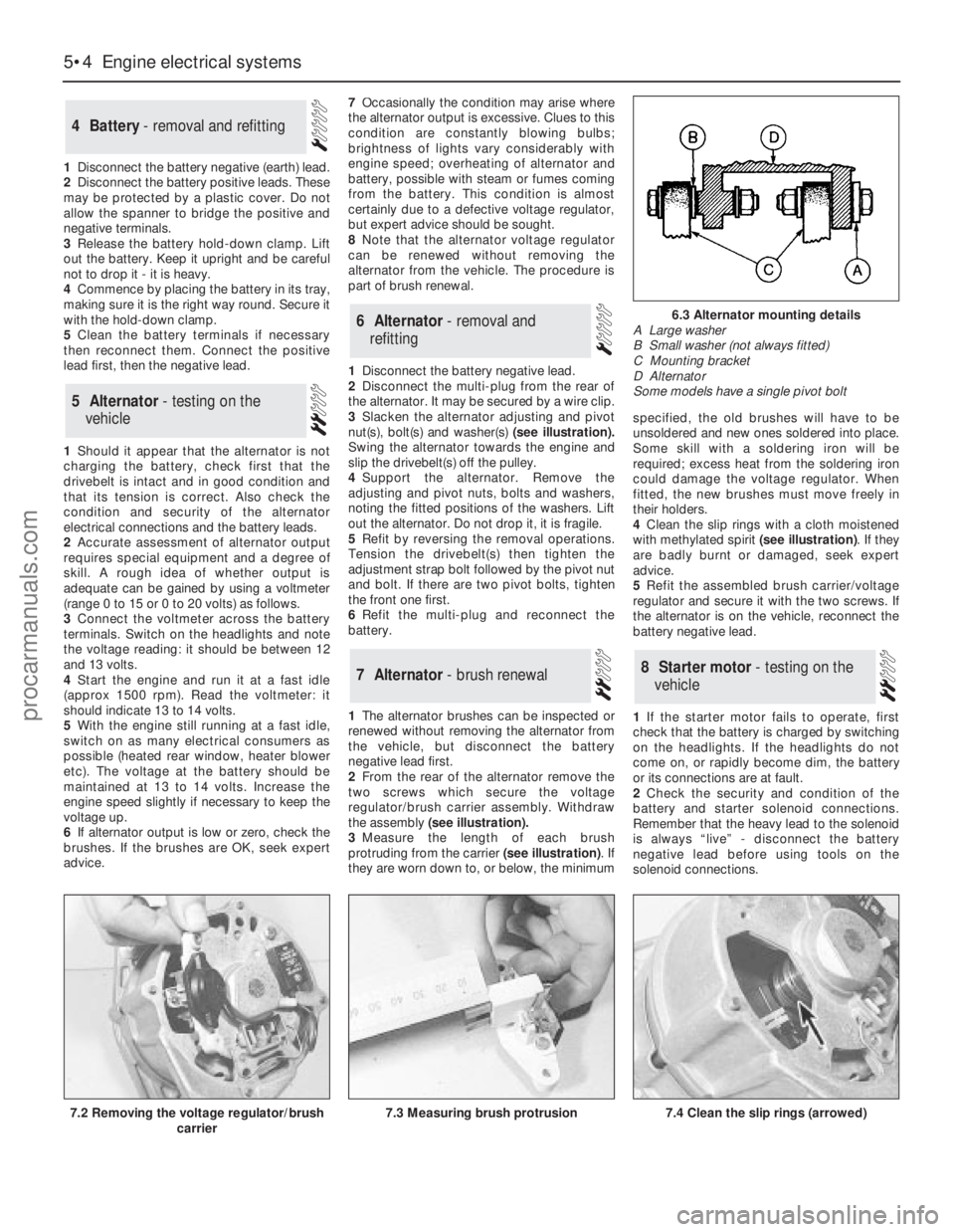
nut(s), bolt(s)and washer(s)(see illustration).
Swing the alternator towards the engine and
slip the drivebelt(s) off the pulley.
4Support the alternator. Remove the
adjusting and pivot nuts, bolts and washers,
noting the fitted positions of the washers. Lift
out the alternator. Do not drop it, it is fragile.
5Refit by reversing the removal operations.
Tension the drivebelt(s) then tighten the
adjustment strap bolt followed by the pivot nut
and bolt. If there are two pivot bolts, tighten
the front one first.
6Refit the multi-plug and reconnect the
battery.
1The alternator brushes can be inspected or
renewed without removing the alternator from
the vehicle, but disconnect the battery
negative lead first.
2From the rear of the alternator remove the
two screws which secure the voltage
regulator/brush carrier assembly. Withdraw
the assembly (see illustration).
3Measure the length of each brush
protruding from the carrier (see illustration). If
they are worn down to, or below, the minimumspecified, the old brushes will have to be
unsoldered and new ones soldered into place.
Some skill with a soldering iron will be
required; excess heat from the soldering iron
could damage the voltage regulator. When
fitted, the new brushes must move freely in
their holders.
4Clean the slip rings with a cloth moistened
with methylated spirit (see illustration). If they
are badly burnt or damaged, seek expert
advice.
5Refit the assembled brush carrier/voltage
regulator and secure it with the two screws. If
the alternator is on the vehicle, reconnect the
battery negative lead.
1If the starter motor fails to operate, first
check that the battery is charged by switching
on the headlights. If the headlights do not
come on, or rapidly become dim, the battery
or its connections are at fault.
2Check the security and condition of the
battery and starter solenoid connections.
Remember that the heavy lead to the solenoid
is always “live” - disconnect the battery
negative lead before using tools on the
solenoid connections.
8Starter motor - testing on the
vehicle7Alternator - brush renewal
6Alternator - removal and
refitting
5Alternator - testing on the
vehicle
4Battery - removal and refitting
5•4Engine electrical systems
7.3 Measuring brush protrusion7.4 Clean the slip rings (arrowed)
6.3 Alternator mounting details
A Large washer
B Small washer (not always fitted)
C Mounting bracket
D Alternator
Some models have a single pivot bolt
7.2 Removing the voltage regulator/brush
carrier
procarmanuals.com