1985 FORD GRANADA ECO mode
[x] Cancel search: ECO modePage 188 of 255
1Disconnect the battery negative lead.
2Remove the steering column upper and
lower shrouds.
3Remove the switch by depressing its two
retaining tabs. Unplug the wiring connector
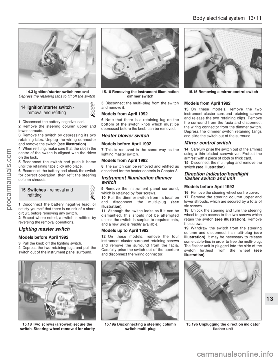
and remove the switch (see illustration).
4When refitting, make sure that the slot in the
centre of the switch is aligned with the driver
on the lock.
5Reconnect the switch and push it home
until the retaining tabs click into place.
6Reconnect the battery and check the switch
for correct operation, then refit the steering
column shrouds.
1Disconnect the battery negative lead, or
satisfy yourself that there is no risk of a short-
circuit, before removing any switch.
2Except where noted, a switch is refitted by
reversing the removal operations.
Lighting master switch
Models before April 1992
3Pull the knob off the lighting switch.
4Depress the two retaining lugs and pull the
switch out of the instrument panel surround. 5Disconnect the multi-plug from the switch
and remove it.
Models from April 1992
6Note that there is a retaining lug on the
bottom of the switch knob which must be
depressed before the knob can be removed.
Heater blower switch
Models before April 1992
7This is removed in the same way as the
lighting master switch.
Models from April 1992
8The switch can be removed and refitted as
described for the heater controls in Chapter 3.
Instrument illumination dimmer
switch
9Remove the instrument panel surround,
which is retained by four screws.
10Pull the dimmer switch from its location
and disconnect the multi-plug (see
illustration).
11Although the switch looks as if it can be
dismantled, this should not be attempted
unless the switch is surplus to requirements,
and a new unit is readily available.
Models up to April 1992
12On these models, remove the four
instrument cluster surround retaining screws
and remove the surround from the facia.
Carefully prise the switch out of the aperture
and disconnect the wiring connector.
Models from April 1992
13On these models, remove the two
instrument cluster surround retaining screws
and release the two retaining clips. Remove
the surround from the facia and disconnect
the wiring connector from the dimmer switch.
Depress the dimmer switch retaining tangs
and slide the switch out of the surround.
Mirror control switch
14Carefully prise the switch out of the armrest
using a thin-bladed screwdriver. Protect the
armrest with a piece of cloth or thick card.
15Disconnect the multi-plug and remove the
switch (see illustration).
Direction indicator/headlight
flasher switch and unit
Models before April 1992
16Remove the steering wheel centre cover.
17Remove the steering column upper and
lower shrouds, which are secured by a total of
six screws.
18Unlock the steering and turn the steering
wheel to gain access to the two screws which
retain the switch (see illustration). Remove
the screws.
19Withdraw the switch from the steering
column and disconnect its multi-plug (see
illustration). It may be necessary to release
some cable-ties in order to free the multi-plug.
The flasher unit is plugged into the side of the
switch furthest from the wheel (see
illustration).15Switches - removal and
refitting
14Ignition/starter switch -
removal and refitting
Body electrical system 13•11
13
14.3 Ignition/starter switch removal
Depress the retaining tabs to lift off the switch15.10 Removing the instrument illumination
dimmer switch15.15 Removing a mirror control switch
15.18 Two screws (arrowed) secure the
switch. Steering wheel removed for clarity15.19a Disconnecting a steering column
switch multi-plug15.19b Unplugging the direction indicator
flasher unit
procarmanuals.com
Page 190 of 255
Heated rear window switch
Models before April 1992
50Remove the instrument panel surround,
which is secured by four screws.
51Carefully prise the switch from its location,
disconnect the multi-plug and remove it.
Models from April 1992
52Using a small flat-bladed screwdriver,
carefully prise the switch out of the centre
facia vent panel and disconnect the wiring
connector.
53On refitting, reconnect the wiring
connector and push the switch in until it clicks
into position.
Foglight switch(es)
54These are removed in the same way as the
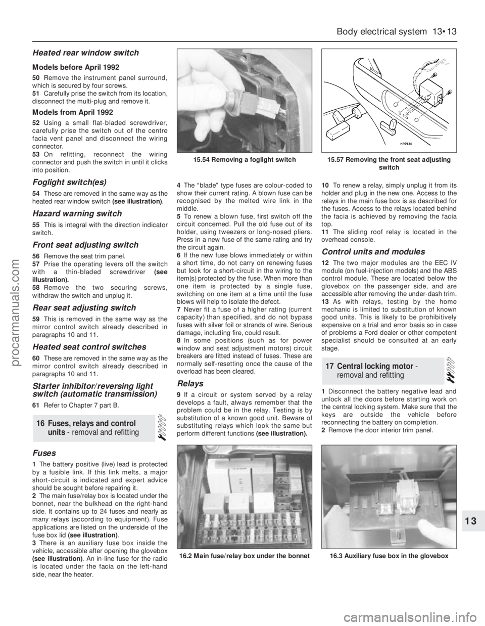
heated rear window switch (see illustration).
Hazard warning switch
55This is integral with the direction indicator
switch.
Front seat adjusting switch
56Remove the seat trim panel.
57Prise the operating levers off the switch
with a thin-bladed screwdriver (see
illustration).
58Remove the two securing screws,
withdraw the switch and unplug it.
Rear seat adjusting switch
59This is removed in the same way as the
mirror control switch already described in
paragraphs 10 and 11.
Heated seat control switches
60These are removed in the same way as the
mirror control switch already described in
paragraphs 10 and 11.
Starter inhibitor/reversing light
switch (automatic transmission)
61Refer to Chapter 7 part B.
Fuses
1The battery positive (live) lead is protected
by a fusible link. If this link melts, a major
short-circuit is indicated and expert advice
should be sought before repairing it.
2The main fuse/relay box is located under the
bonnet, near the bulkhead on the right-hand
side. It contains up to 24 fuses and nearly as
many relays (according to equipment). Fuse
applications are listed on the underside of the
fuse box lid (see illustration).
3There is an auxiliary fuse box inside the
vehicle, accessible after opening the glovebox
(see illustration). An in-line fuse for the radio
is located under the facia on the left-hand
side, near the heater.4The“blade” type fuses are colour-coded to
show their current rating. A blown fuse can be
recognised by the melted wire link in the
middle.
5To renew a blown fuse, first switch off the
circuit concerned. Pull the old fuse out of its
holder, using tweezers or long-nosed pliers.
Press in a new fuse of the same rating and try
the circuit again.
6If the new fuse blows immediately or within
a short time, do not carry on renewing fuses
but look for a short-circuit in the wiring to the
item(s) protected by the fuse. When more than
one item is protected by a single fuse,
switching on one item at a time until the fuse
blows will help to isolate the defect.
7Never fit a fuse of a higher rating (current
capacity) than specified, and do not bypass
fuses with silver foil or strands of wire. Serious
damage, including fire, could result.
8In some positions (such as for power
window and seat adjustment motors) circuit
breakers are fitted instead of fuses. These are
normally self-resetting once the cause of the
overload has been cleared.
Relays
9If a circuit or system served by a relay
develops a fault, always remember that the
problem could be in the relay. Testing is by
substitution of a known good unit. Beware of
substituting relays which look the same but
perform different functions(see illustration).10To renew a relay, simply unplug it from its
holder and plug in the new one. Access to the
relays in the main fuse box is as described for
the fuses. Access to the relays located behind
the facia is achieved by removing the facia
top.
11The sliding roof relay is located in the
overhead console.
Control units and modules
12The two major modules are the EEC IV
module (on fuel-injection models) and the ABS
control module. These are located below the
glovebox on the passenger side, and are
accessible after removing the under-dash trim.
13As with relays, testing by the home
mechanic is limited to substitution of known
good units. This is likely to be prohibitively
expensive on a trial and error basis so in case
of problems a Ford dealer or other competent
specialist should be consulted at an early
stage.
1Disconnect the battery negative lead and
unlock all the doors before starting work on
the central locking system. Make sure that the
keys are outside the vehicle before
reconnecting the battery on completion.
2Remove the door interior trim panel.
17Central locking motor -
removal and refitting
16Fuses, relays and control
units - removal and refitting
Body electrical system 13•13
13
15.54 Removing a foglight switch15.57 Removing the front seat adjusting
switch
16.2 Main fuse/relay box under the bonnet16.3 Auxiliary fuse box in the glovebox
procarmanuals.com
Page 193 of 255
1Remove the overhead console.
2Remove the three bolts which secure the
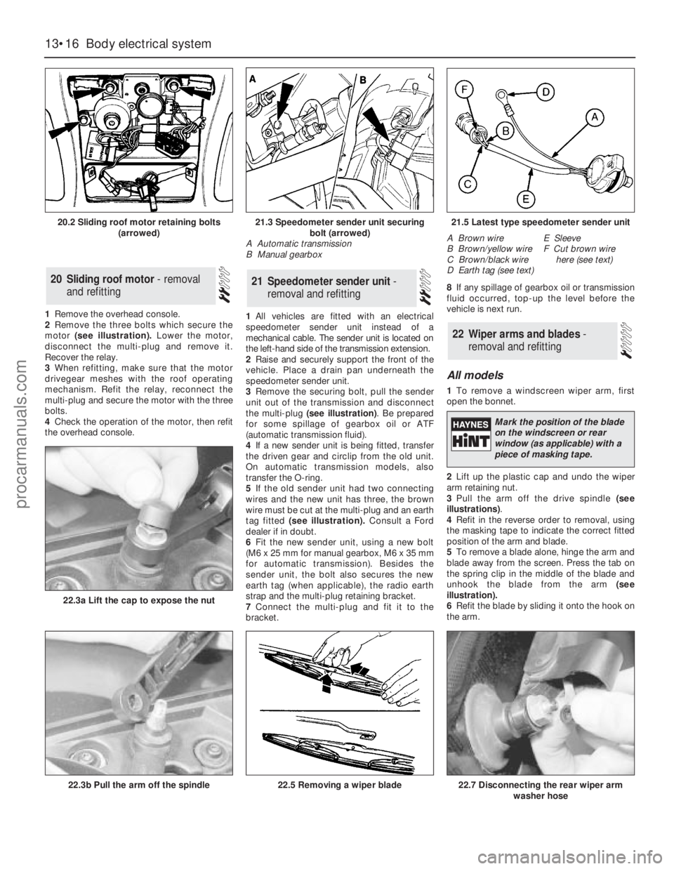
motor (see illustration).Lower the motor,
disconnect the multi-plug and remove it.
Recover the relay.
3When refitting, make sure that the motor
drivegear meshes with the roof operating
mechanism. Refit the relay, reconnect the
multi-plug and secure the motor with the three
bolts.
4Check the operation of the motor, then refit
the overhead console.1All vehicles are fitted with an electrical
speedometer sender unit instead of a
mechanical cable. The sender unit is located on
the left-hand side of the transmission extension.
2Raise and securely support the front of the
vehicle. Place a drain pan underneath the
speedometer sender unit.
3Remove the securing bolt, pull the sender
unit out of the transmission and disconnect
the multi-plug (see illustration). Be prepared
for some spillage of gearbox oil or ATF
(automatic transmission fluid).
4If a new sender unit is being fitted, transfer
the driven gear and circlip from the old unit.
On automatic transmission models, also
transfer the O-ring.
5If the old sender unit had two connecting
wires and the new unit has three, the brown
wire must be cut at the multi-plug and an earth
tag fitted (see illustration).Consult a Ford
dealer if in doubt.
6Fit the new sender unit, using a new bolt
(M6 x 25 mm for manual gearbox, M6 x 35 mm
for automatic transmission). Besides the
sender unit, the bolt also secures the new
earth tag (when applicable), the radio earth
strap and the multi-plug retaining bracket.
7Connect the multi-plug and fit it to the
bracket.8If any spillage of gearbox oil or transmission
fluid occurred, top-up the level before the
vehicle is next run.
All models
1To remove a windscreen wiper arm, first
open the bonnet.
2Lift up the plastic cap and undo the wiper
arm retaining nut.
3Pull the arm off the drive spindle (see
illustrations).
4Refit in the reverse order to removal, using
the masking tape to indicate the correct fitted
position of the arm and blade.
5To remove a blade alone, hinge the arm and
blade away from the screen. Press the tab on
the spring clip in the middle of the blade and
unhook the blade from the arm (see
illustration).
6Refit the blade by sliding it onto the hook on
the arm.
22Wiper arms and blades -
removal and refitting
21Speedometer sender unit -
removal and refitting20Sliding roof motor - removal
and refitting
13•16Body electrical system
20.2 Sliding roof motor retaining bolts
(arrowed)
22.3b Pull the arm off the spindle
22.3a Lift the cap to expose the nut
22.5 Removing a wiper blade22.7 Disconnecting the rear wiper arm
washer hose
21.3 Speedometer sender unit securing
bolt (arrowed)
A Automatic transmission
B Manual gearbox21.5 Latest type speedometer sender unit
A Brown wire
B Brown/yellow wire
C Brown/black wire
D Earth tag (see text)E Sleeve
F Cut brown wire
here (see text)
Mark the position of the blade
on the windscreen or rear
window (as applicable) with a
piece of masking tape.
procarmanuals.com
Page 195 of 255
Computer module and bulb
Models before April 1992
2Remove the instrument panel surround,
which is secured by four screws.
3Carefully pull the module from its location.
Release the multi-plug by pressing
downwards and disconnect it.
4The module illumination bulbholder may
now be extracted by gripping it with pliers and
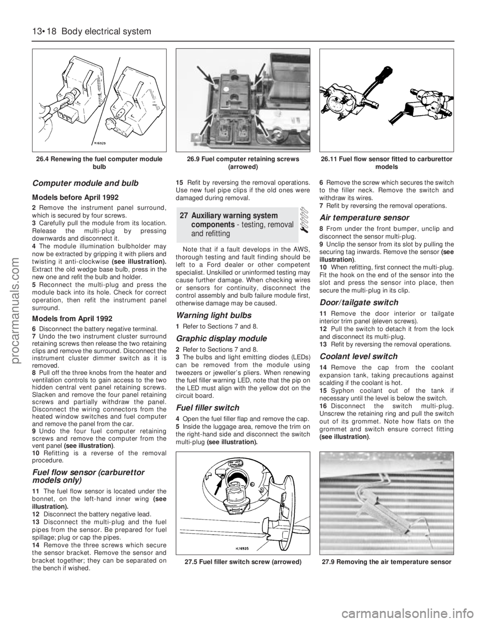
twisting it anti-clockwise (see illustration).
Extract the old wedge base bulb, press in the
new one and refit the bulb and holder.
5Reconnect the multi-plug and press the
module back into its hole. Check for correct
operation, then refit the instrument panel
surround.
Models from April 1992
6Disconnect the battery negative terminal.
7Undo the two instrument cluster surround
retaining screws then release the two retaining
clips and remove the surround. Disconnect the
instrument cluster dimmer switch as it is
removed.
8Pull off the three knobs from the heater and
ventilation controls to gain access to the two
hidden central vent panel retaining screws.
Slacken and remove the four panel retaining
screws and partially withdraw the panel.
Disconnect the wiring connectors from the
heated window switches and fuel computer
and remove the panel from the car.
9Undo the four fuel computer retaining
screws and remove the computer from the
vent panel (see illustration).
10Refitting is a reverse of the removal
procedure.
Fuel flow sensor (carburettor
models only)
11The fuel flow sensor is located under the
bonnet, on the left-hand inner wing (see
illustration).
12Disconnect the battery negative lead.
13Disconnect the multi-plug and the fuel
pipes from the sensor. Be prepared for fuel
spillage; plug or cap the pipes.
14Remove the three screws which secure
the sensor bracket. Remove the sensor and
bracket together; they can be separated on
the bench if wished.15Refit by reversing the removal operations.
Use new fuel pipe clips if the old ones were
damaged during removal.
Note that if a fault develops in the AWS,
thorough testing and fault finding should be
left to a Ford dealer or other competent
specialist. Unskilled or uninformed testing may
cause further damage. When checking wires
or sensors for continuity, disconnect the
control assembly and bulb failure module first,
otherwise damage may be caused.
Warning light bulbs
1Refer to Sections 7 and 8.
Graphic display module
2Refer to Sections 7 and 8.
3The bulbs and light emitting diodes (LEDs)
can be removed from the module using
tweezers or jeweller’s pliers. When renewing
the fuel filler warning LED, note that the pip on
the LED must align with the yellow dot on the
circuit board.
Fuel filler switch
4Open the fuel filler flap and remove the cap.
5Inside the luggage area, remove the trim on
the right-hand side and disconnect the switch
multi-plug(see illustration).6Remove the screw which secures the switch
to the filler neck. Remove the switch and
withdraw its wires.
7Refit by reversing the removal operations.
Air temperature sensor
8From under the front bumper, unclip and
disconnect the sensor multi-plug.
9Unclip the sensor from its slot by pulling the
securing tag inwards. Remove the sensor (see
illustration).
10When refitting, first connect the multi-plug.
Fit the hook on the end of the sensor into the
slot and press the sensor into place, then
secure the multi-plug in its clip.
Door/tailgate switch
11Remove the door interior ortailgate
interior trim panel (eleven screws).
12Pull the switch to detach it from the lock
and disconnect its multi-plug.
13Refit by reversing the removal operations.
Coolant level switch
14Remove the cap from the coolant
expansion tank, taking precautions against
scalding if the coolant is hot.
15Syphon coolant out of the tank if
necessary until the level is below the switch.
16Disconnect the switch multi-plug.
Unscrew the retaining ring and pull the switch
out of its grommet. Note how flats on the
grommet and switch ensure correct fitting
(see illustration).
27Auxiliary warning system
components - testing, removal
and refitting
13•18Body electrical system
26.4 Renewing the fuel computer module
bulb
27.5 Fuel filler switch screw (arrowed)27.9 Removing the air temperature sensor
26.9 Fuel computer retaining screws
(arrowed)26.11 Fuel flow sensor fitted to carburettor
models
procarmanuals.com
Page 196 of 255
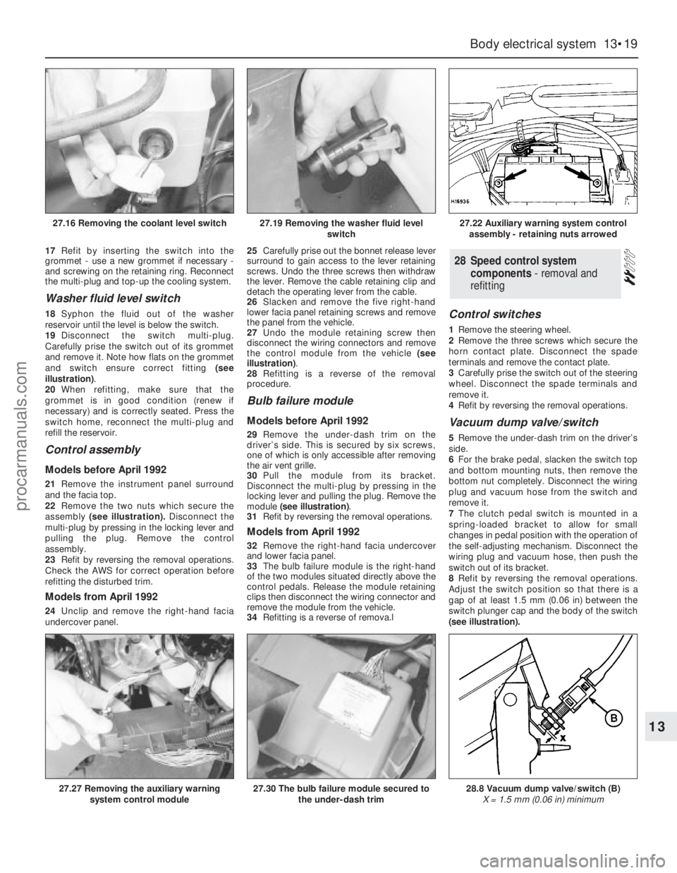
17Refit by inserting the switch into the
grommet - use a new grommet if necessary -
and screwing on the retaining ring. Reconnect
the multi-plug and top-up the cooling system.
Washer fluid level switch
18Syphon the fluid out of the washer
reservoir until the level is below the switch.
19Disconnect the switch multi-plug.
Carefully prise the switch out of its grommet
and remove it. Note how flats on the grommet
and switch ensure correct fitting (see
illustration).
20When refitting, make sure that the
grommet is in good condition (renew if
necessary) and is correctly seated. Press the
switch home, reconnect the multi-plug and
refill the reservoir.
Control assembly
Models before April 1992
21Remove the instrument panel surround
and the facia top.
22Remove the two nuts which secure the
assembly(see illustration).Disconnect the
multi-plug by pressing in the locking lever and
pulling the plug. Remove the control
assembly.
23Refit by reversing the removal operations.
Check the AWS for correct operation before
refitting the disturbed trim.
Models from April 1992
24Unclip and remove the right-hand facia
undercover panel.25Carefully prise out the bonnet release lever
surround to gain access to the lever retaining
screws. Undo the three screws then withdraw
the lever. Remove the cable retaining clip and
detach the operating lever from the cable.
26Slacken and remove the five right-hand
lower facia panel retaining screws and remove
the panel from the vehicle.
27Undo the module retaining screw then
disconnect the wiring connectors and remove
the control module from the vehicle (see
illustration).
28Refitting is a reverse of the removal
procedure.
Bulb failure module
Models before April 1992
29Remove the under-dash trim on the
driver’s side. This is secured by six screws,
one of which is only accessible after removing
the air vent grille.
30Pull the module from its bracket.
Disconnect the multi-plug by pressing in the
locking lever and pulling the plug. Remove the
module (see illustration).
31Refit by reversing the removal operations.
Models from April 1992
32Remove the right-hand facia undercover
and lower facia panel.
33The bulb failure module is the right-hand
of the two modules situated directly above the
control pedals. Release the module retaining
clips then disconnect the wiring connector and
remove the module from the vehicle.
34Refitting is a reverse of remova.l
Control switches
1Remove the steering wheel.
2Remove the three screws which secure the
horn contact plate. Disconnect the spade
terminals and remove the contact plate.
3Carefully prise the switch out of the steering
wheel. Disconnect the spade terminals and
remove it.
4Refit by reversing the removal operations.
Vacuum dump valve/switch
5Remove the under-dash trim on the driver’s
side.
6For the brake pedal, slacken the switch top
and bottom mounting nuts, then remove the
bottom nut completely. Disconnect the wiring
plug and vacuum hose from the switch and
remove it.
7The clutch pedal switch is mounted in a
spring-loaded bracket to allow for small
changes in pedal position with the operation of
the self-adjusting mechanism. Disconnect the
wiring plug and vacuum hose, then push the
switch out of its bracket.
8Refit by reversing the removal operations.
Adjust the switch position so that there is a
gap of at least 1.5 mm (0.06 in) between the
switch plunger cap and the body of the switch
(see illustration).
28Speed control system
components - removal and
refitting
Body electrical system 13•19
13
27.16 Removing the coolant level switch27.19 Removing the washer fluid level
switch27.22 Auxiliary warning system control
assembly - retaining nuts arrowed
27.27 Removing the auxiliary warning
system control module27.30 The bulb failure module secured to
the under-dash trim28.8 Vacuum dump valve/switch (B)
X = 1.5 mm (0.06 in) minimum
procarmanuals.com
Page 197 of 255
Speed control module
Models before April 1992
9Refer to Section 27. The speed control
module shares the same mountings as the
AWS module; the AWS module is larger.
Models from April 1992
10The speed control module fitted to these
models is situated behind the glovebox on the
left-hand side of the facia. To gain access to
the module remove the left-hand facia
undercover panel. The speed control module
is vertically mounted just to the right of the
engine management module. Push the module
upwards to release the retaining clips then
lower it out from under the facia and
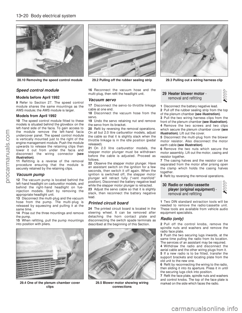
disconnect the wiring connector (see
illustration).
11Refitting is a reverse of the removal
procedure ensuring that the module is
securely retained by the retaining clips.
Vacuum pump
12The vacuum pump is located behind the
left-hand headlight on carburettor models, and
behind the right-hand headlight on fue-
injection models. Start by removing the
appropriate headlight unit.
13Disconnect the multi-plug and the vacuum
hose from the pump. The multi-plug is
released by squeezing and pulling it at the
same time.
14Prise out the three mountings and remove
the pump.
15When refitting, pull the pump mountings
into position with pliers. 16Reconnect the vacuum hose and the
multi-plug, then refit the headlight unit.
Vacuum servo
17Disconnect the servo-to-throttle linkage
cable at one end.
18Disconnect the vacuum hose from the
servo.
19Undo the servo retaining nut and remove
the servo from its bracket.
20Refit by reversing the removal operations.
On all but 2.0 litre carburettor models, adjust
the cable so that it is slightly slack when the
throttle linkage is in the idle position (pedal
released).
21On 2.0 litre carburettor models, the
stepper motor plunger must be withdrawn
before the cable is adjusted. Proceed as
follows.
22Observe the stepper motor plunger. Have
an assistant switch on the ignition for a few
seconds, then switch it off again. When the
ignition is switched off, the stepper motor
plunger will retract fully (“vent manifold”
position). Disconnect the battery negative lead
while the stepper motor plunger is retracted.
23Adjust the servo cable so that it is slightly
slack, then reconnect the battery negative
lead.
Printed circuit board
24The printed circuit board is located in the
steering wheel. It can be removed after
detaching the horn contact plate and
disconnecting the switch spade terminals as
described at the beginning of this Section.1Disconnect the battery negative lead.
2Pull off the rubber sealing strip from the top
of the plenum chamber (see illustration).
3Pull the two wiring harness clips from the
front of the plenum chamber (see illustration).
4Remove the two screws and two clips
which secure the plenum chamber cover (see
illustration). Lift out the cover.
5Disconnect the multi-plug from the blower
motor resistor. Also disconnect the motor
earth cable (see illustration).
6Remove the two nuts which secure the
motor assembly. Lift out the motor, casing and
resistor together.
7The casing halves and the resistor can be
separated from the motor after prising open
the clamp which holds the casing halves
together.
8Refit by reversing the removal operations.
1Two DIN standard extraction tools will be
needed to remove the radio/cassette unit.
These tools are available from vehicle audio
equipment specialists.
Radio (only)
2Pull off the control knobs, remove the
spindle nuts and washers and remove the
radio face plate.
3Push the two securing lugs inwards, at the
same time pulling the radio from its location.
The services of an assistant may be required.
4Withdraw the radio and disconnect the
aerial cable and the other wiring plugs from it.
5If a new radio is to be fitted, transfer the
support brackets and locating plate from the
old unit to the new one.
6Refit by reconnecting the wiring to the radio,
then sliding it into its aperture. Press it in until
the securing lugs click into position.
7Refit the face plate, spindle nuts and washers
and control knobs. The top of the face plate is
marked on the side which faces the radio.
30Radio or radio/cassette
player (original equipment) -
removal and refitting
29Heater blower motor -
removal and refitting
13•20Body electrical system
28.10 Removing the speed control module
29.4 One of the plenum chamber cover
clips29.5 Blower motor showing wiring
connections
29.2 Pulling off the rubber sealing strip29.3 Pulling out a wiring harness clip
procarmanuals.com
Page 198 of 255
8If a new unit has been fitted, trim it by tuning
in a weak medium wave station (around 1500
kHz/200 m) and turning the trimmer screw in
either direction until the best reception is
obtained. On the radio originally fitted, the
trimmer screw is on the front face of the unit;
for other types of radio, consult the
manufacturer’s instructions. Electronic units
are normally self-trimming.
Radio/cassette unit
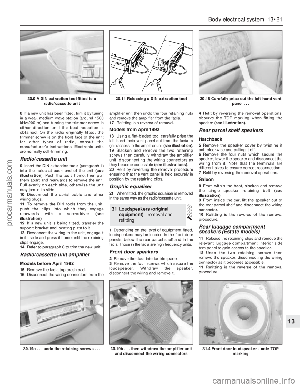
9Insert the DIN extraction tools (paragraph 1)
into the holes at each end of the unit (see
illustration). Push the tools home, then pull
them apart and rearwards to remove the unit.
Pull evenly on each side, otherwise the unit
may jam in its slide.
10Disconnect the aerial cable and other
wiring plugs.
11To remove the DIN tools from the unit,
push the clips into which they engage
rearwards with a screwdriver (see
illustration).
12If a new unit is being fitted, transfer the
support bracket and locating plate to it.
13Reconnect the wiring to the unit, engage it
in its slide and press it home until the retaining
clips engage.
14Refer to paragraph 8 to trim the new unit.
Radio/cassette unit amplifier
Models before April 1992
15Remove the facia top crash pad.
16Disconnect the wiring connectors from theamplifier unit then undo the four retaining nuts
and remove the amplifier from the facia.
17Refitting is a reverse of removal.
Models from April 1992
18Using a flat-bladed tool carefully prise the
left-hand facia vent panel out from the facia to
gain access to the amplifier unit (see illustration).
19Slacken and remove the two retaining
screws then carefully withdraw the amplifier
unit, disconnecting the wiring connectors as
they become accessible (see illustrations).
20Refit by reversing the removal procedure
ensuring that the vent panel is held securely in
position by the retaining clips.
Graphic equaliser
21When fitted, the graphic equaliser is removed
in the same way as the radio/cassette unit.
1Depending on the level of equipment fitted,
loudspeakers may be located in the front door
panels, below the rear parcel shelf and in the
facia. Those in the facia are high frequency units.
Front door speakers
2Remove the door interior trim panel.
3Remove the four screws which secure the
loudspeaker. Withdraw the speaker,
disconnect the wiring and remove it.4Refit by reversing the removal operations;
observe the TOP marking when fitting the
speaker (see illustration).
Rear parcel shelf speakers
Hatchback
5Remove the speaker cover by twisting it
anti-clockwise and pulling it off.
6Remove the four nuts which secure the
speaker, lower the speaker and disconnect the
wiring from it. Note that the terminals are
different sizes to ensure correct reconnection.
7Refit by reversing the removal operations.
Saloon
8From within the boot, slacken and remove
the single speaker retaining bolt (see
illustration).
9From inside the car, lift the speaker out of
the rear parcel shelf and disconnect the wiring
connector.
10Refitting is the reverse of the removal
procedure.
Rear luggage compartment
speakers (Estate models)
11Release the retaining clips and remove the
relevant luggage compartment interior side
trim panel to gain access to the speaker.
12Undo the two retaining screws then
remove the speaker, disconnecting the wiring
connector as it becomes accessible.
13Refitting is the reverse of the removal
procedure.
31Loudspeakers (original
equipment) - removal and
refitting
Body electrical system 13•21
13
30.9 A DIN extraction tool fitted to a
radio/cassette unit30.11 Releasing a DIN extraction tool30.18 Carefully prise out the left-hand vent
panel . . .
30.19a . . . undo the retaining screws . . .30.19b . . . then withdraw the amplifier unit
and disconnect the wiring connectors31.4 Front door loudspeaker - note TOP
marking
procarmanuals.com
Page 199 of 255
High frequency units
14Remove the instrument panel surround
and the facia top.
15Remove the two screws which secure the
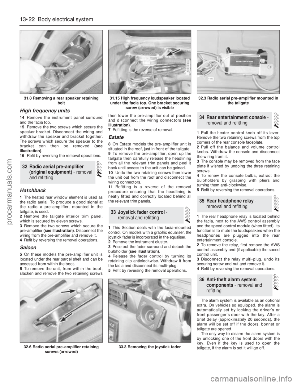
speaker bracket. Disconnect the wiring and
withdraw the speaker and bracket together.
The screws which secure the speaker to the
bracket can then be removed (see
illustration).
16Refit by reversing the removal operations.
Hatchback
1The heated rear window element is used as
the radio aerial. To produce a good signal at
the radio a pre-amplifier, mounted in the
tailgate, is used.
2Remove the tailgate interior trim panel,
which is secured by eleven screws.
3Remove the two screws which secure the
pre-amplifier (see illustration). Disconnect the
wiring from the pre-amplifier and remove it.
4Refit by reversing the removal operations.
Saloon
5On these models the pre-amplifier unit is
located under the rear parcel shelf and can be
accessed from within the boot.
6To remove the unit, from within the boot,
slacken and remove the two retaining screwsthen lower the pre-amplifier out of position
and disconnect the wiring connectors (see
illustration).
7Refitting is the reverse of removal.
Estate
8On Estate models the pre-amplifier unit is
situated in the roof, just in front of the tailgate.
9To remove the pre-amplifier, open up the
tailgate then carefully release the headlining
from all the relevant trim panels and peel it
back until access to the unit can be gained.
10Undo the two retaining screws then lower
the unit out from the roof and disconnect the
wiring connectors.
11Refitting is a reverse of the removal
procedure ensuring that the headlining is
neatly fitted and correctly located behind all
the relevant trim panels.
1This Section deals with the facia-mounted
control. On models with a graphic equaliser, the
joystick fader is incorporated in the equaliser.
2Remove the instrument cluster.
3Prise out the fader surround and detach the
bulbholder (see illustration).
4Release the fader control by turning its
retaining clip anticlockwise. Withdraw it from
the facia and disconnect its multi-plug.
5Refit by reversing the removal operations.1Pull the heater control knob off its lever.
Remove the two retaining screws from the top
corners of the rear console faceplate.
2Pull off the balance and volume control
knobs. Withdraw the console and disconnect
the wiring from it.
3The console may be removed from the face
plate if wished by undoing the three retaining
screws.
4To renew the console bulbs, extract the
bulbholders by grasping with pliers and
turning them anti-clockwise.
5Refit by reversing the removal operations.
1The rear headphone relay is located behind
the facia, next to the AWS control assembly
and the speed control module (when fitted). Its
function is to mute the loudspeakers when the
headphones are plugged into the rear
entertainment console.
2To remove the relay, first remove the AWS
control assembly and (if applicable) the speed
control unit.
3Disconnect the relay multi-plug, undo its
securing screw and nut and remove it.
4Refit by reversing the removal operations.
The alarm system is available as an optional
extra. On vehicles so equipped, the alarm is
automatically set by locking the driver’s or
front passenger’s door with the key. After a
brief delay (approximately 20 seconds), the
alarm will be set off if the doors, bonnet or
tailgate are opened.
The only way to disarm the alarm system is
by unlocking one of the front doors with the
key. Even if the key is used to open the
tailgate, if the alarm is set it will go off.
36Anti-theft alarm system
components - removal and
refitting
35Rear headphone relay -
removal and refitting
34Rear entertainment console -
removal and refitting
33Joystick fader control -
removal and refitting
32Radio aerial pre-amplifier
(original equipment) - removal
and refitting
13•22Body electrical system
31.8 Removing a rear speaker retaining
bolt
32.6 Radio aerial pre-amplifier retaining
screws (arrowed)33.3 Removing the joystick fader
31.15 High frequency loudspeaker located
under the facia top. One bracket securing
screw (arrowed) is visible32.3 Radio aerial pre-amplifier mounted in
the tailgate
procarmanuals.com