1985 FORD GRANADA water pump
[x] Cancel search: water pumpPage 85 of 255
Cooling system
The cooling system is of pressurised type
and includes a front mounted crossflow
radiator, belt-driven water pump, temperature-
sensitive thermo-viscous fan (on DOHC
models, an electrically-operated cooling fan is
fitted, operated by a switch in the thermostat
housing), wax type thermostat, and an
expansion and degas tank.
The radiator matrix is of copper and brass
construction and the end tanks are of plastic.
On automatic transmission models the right-
hand side end tank incorporates the
transmission oil cooler.
The thermostat is located behind the water
outlet elbow at the front of the cylinder head
on OHCmodels, and on the front of the water
pump on V6 models. Its purpose is to ensure
rapid engine warm-up by restricting the flow of
coolant in the engine when cold, and also to
assist in regulating the normal operating
temperature of the engine.
The expansion tank incorporates a pressure
cap which effectively pressurises the cooling
system as the coolant temperature rises,
thereby increasing the boiling point of the
coolant. The tank also has a further degas
function. Any accumulation of air bubbles in
the coolant, in particular in the thermostat
housing and the radiator, is returned to the
tank and released in the air space thus
maintaining the efficiency of the coolant.
On models fitted with the auxiliary warning
system, the expansion tank contains a level
sensor which operates a warning light if the
coolant level falls significantly.
When the engine is started from cold, the
water pump circulates coolant around the
cylinder block, cylinder head(s) and inlet
manifold. The warm coolant passes through
the automatic choke housing (when
applicable) and through the heater matrix
before returning to the engine. As the coolant
expands, the level in the expansion tank rises.
Circulation of coolant through the radiator is
prevented while the thermostat is shut. When
the coolant reaches the predeterminedtemperature the thermostat opens and hot
water passes through the top hose to the top
of the radiator. As the water circulates down
through the radiator, it is cooled by the
passage of air past the radiator when the car is
in forward motion, supplemented by the action
of the thermo-viscous fan when necessary.
Having reached the bottom of the radiator, the
water is now cool and the cycle is repeated.
Circulation of water continues through the
expansion tank, inlet manifold and heater at all
times; the heater temperature control being by
an air flap.
The thermo-viscous fan is controlled by the
temperature of air behind the radiator. When
the air temperature reaches a predetermined
level, a bi-metallic coil commences to open a
valve within the unit and silicon fluid is fed
through a system of vanes. Half of the vanes
are driven directly by the water pump and the
remaining half are connected to the fan blades.
The vanes are arranged so that drive is
transmitted to the fan blades in relation to the
drag or viscosity of the fluid, and this in turn
depends on ambient temperature and engine
speed. The fan is therefore only operated when
required, and compared with direct drive type
fan represents a considerable improvement in
fuel economy, drivebelt wear and fan noise.
Air conditioning
Air conditioning is fitted as standard on
Scorpio models and is optionally available on
some other models. In conjunction with the
heater, the system enables any reasonable air
temperature to be achieved inside the car, it
also reduces the humidity of the incoming air,
aiding demisting even when cooling is not
required.
The refrigeration side of the air conditioning
system functions in a similar way to a
domestic refrigerator. A compressor, belt-
driven from the crankshaft pulley, draws
refrigerant in its gaseous phase from an
evaporator. The compressed refrigerant
passes through a condenser where it loses
heat and enters its liquid phase. After
dehydration the refrigerant returns to the
evaporator where it absorbs heat from air
passing over the evaporator fins. The
refrigerant becomes a gas again and the cycle
is repeated.Various subsidiary controls and sensors
protect the system against excessive
temperature and pressures. Additionally,
engine idle speed is increased when the
system is in use to compensate for the
additional load imposed by the compressor.
Precautions
Antifreeze mixture
Antifreeze mixture is poisonous. Keep it out
of reach of children and pets. Wash splashes
off skin and clothing with plenty of water.
Wash splashes off vehicle paintwork to avoid
discolouration.
Antifreeze/water mixture must be renewed
every two years to preserve its anti-corrosive
properties. In climates where antifreeze
protection is unnecessary, a corrosion
inhibitor may be used instead - consult a Ford
dealer. Never run the engine for long periods
with plain water as coolant. Only use the
specified antifreeze, as inferior brands may not
contain the necessary corrosion inhibitors, or
may break down at high temperatures.
Antifreeze containing methanol is particularly
to be avoided, as the methanol evaporates.
The specified mixture is 45 to 50%
antifreeze and 50 to 55% clean soft water (by
volume). Mix the required quantity in a clean
container.
Air conditioning refrigerant
Although the refrigerant is not itself toxic, in
the presence of a naked flame (or a lighted
cigarette) it forms a highly toxic gas. Liquid
refrigerant spilled on the skin will cause
frostbite. If refrigerant enters the eyes, rinse
them with a dilute solution of boric acid and
seek medical advice immediately.
In view of the above points, and of the need
for specialised equipment for evacuating and
recharging the system, any work which
requires the disconnection of a refrigerant line
must be left to a specialist.
Do not allow refrigerant lines to be exposed
to temperatures above 110°C (230°F) - eg
during welding or paint drying operations and
do not operate the air conditioning system if it
is known to be short of refrigerant, or further
damage may result.
1General information and
precautions
3•2Cooling, heating and ventilation systems
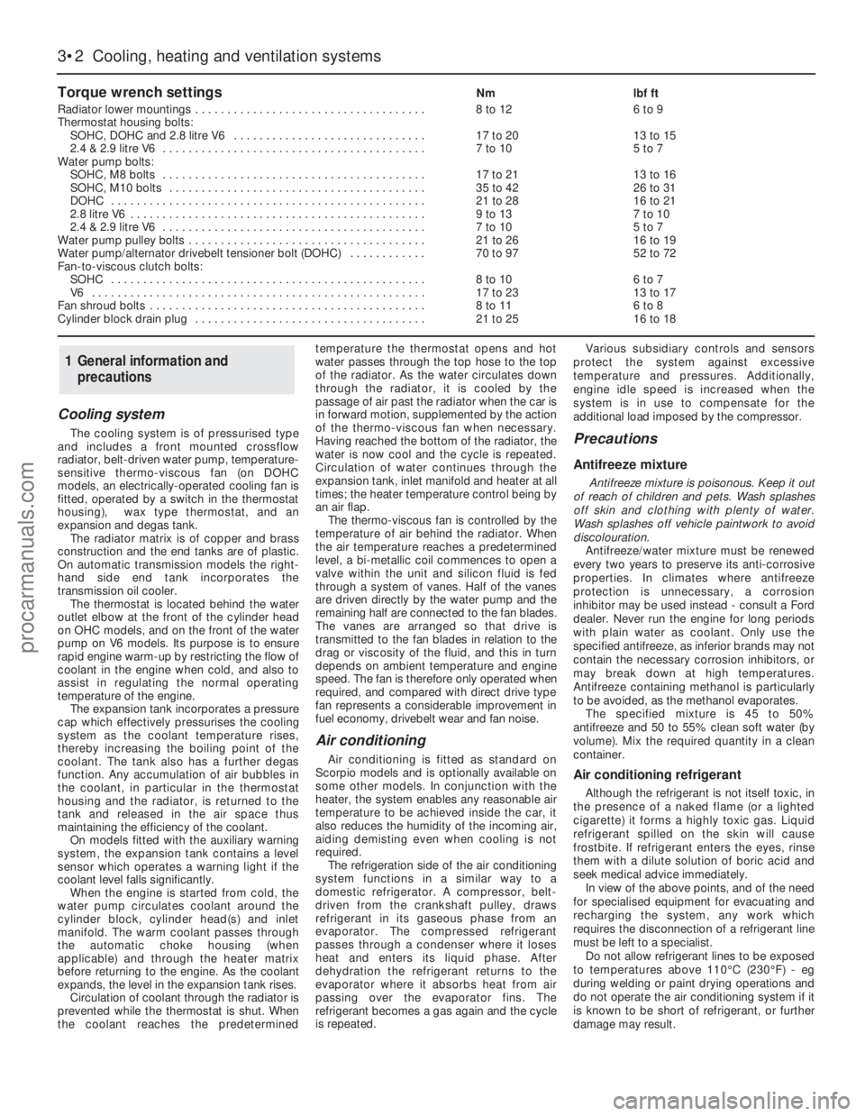
Torque wrench settingsNmlbf ft
Radiator lower mountings . . . . . . . . . . . . . . . . . . . . . . . . . . . . . . . . . . . .8 to 126 to 9
Thermostat housing bolts:
SOHC, DOHC and 2.8 litre V6 . . . . . . . . . . . . . . . . . . . . . . . . . . . . . .17 to 2013 to 15
2.4 & 2.9 litre V6 . . . . . . . . . . . . . . . . . . . . . . . . . . . . . . . . . . . . . . . . .7 to 105 to 7
Water pump bolts:
SOHC, M8 bolts . . . . . . . . . . . . . . . . . . . . . . . . . . . . . . . . . . . . . . . . .17 to 2113 to 16
SOHC, M10 bolts . . . . . . . . . . . . . . . . . . . . . . . . . . . . . . . . . . . . . . . .35 to 4226 to 31
DOHC . . . . . . . . . . . . . . . . . . . . . . . . . . . . . . . . . . . . . . . . . . . . . . . . .21 to 2816 to 21
2.8 litre V6 . . . . . . . . . . . . . . . . . . . . . . . . . . . . . . . . . . . . . . . . . . . . . .9 to 137 to 10
2.4 & 2.9 litre V6 . . . . . . . . . . . . . . . . . . . . . . . . . . . . . . . . . . . . . . . . .7 to 105 to 7
Water pump pulley bolts . . . . . . . . . . . . . . . . . . . . . . . . . . . . . . . . . . . . .21 to 2616 to 19
Water pump/alternator drivebelt tensioner bolt (DOHC) . . . . . . . . . . . .70 to 9752 to 72
Fan-to-viscous clutch bolts:
SOHC . . . . . . . . . . . . . . . . . . . . . . . . . . . . . . . . . . . . . . . . . . . . . . . . .8 to 106 to 7
V6 . . . . . . . . . . . . . . . . . . . . . . . . . . . . . . . . . . . . . . . . . . . . . . . . . . . .17 to 2313 to 17
Fan shroud bolts . . . . . . . . . . . . . . . . . . . . . . . . . . . . . . . . . . . . . . . . . . .8 to 116 to 8
Cylinder block drain plug . . . . . . . . . . . . . . . . . . . . . . . . . . . . . . . . . . . .21 to 2516 to 18
procarmanuals.com
Page 86 of 255
See Chapter 1, Section 46.
See Chapter 1, Section 46.
See Chapter 1, Section 46.
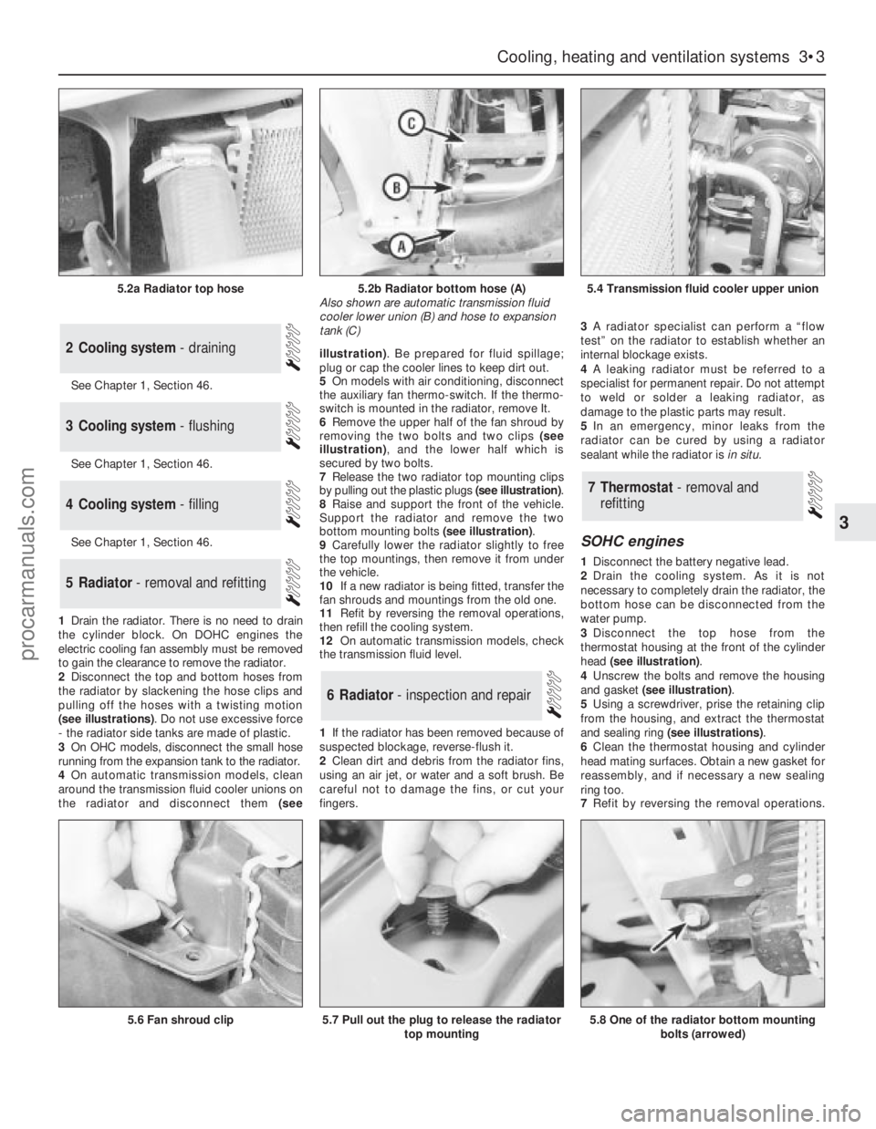
1Drain the radiator. There is no need to drain
the cylinder block. On DOHC engines the
electric cooling fan assembly must be removed
to gain the clearance to remove the radiator.
2Disconnect the top and bottom hoses from
the radiator by slackening the hose clips and
pulling off the hoses with a twisting motion
(see illustrations). Do not use excessive force
- the radiator side tanks are made of plastic.
3On OHCmodels, disconnect the small hose
running from the expansion tank to the radiator.
4On automatic transmission models, clean
around the transmission fluid cooler unions on
the radiator and disconnect them (seeillustration). Be prepared for fluid spillage;
plug or cap the cooler lines to keep dirt out.
5On models with air conditioning, disconnect
the auxiliary fan thermo-switch. If the thermo-
switch is mounted in the radiator, remove It.
6Remove the upper half of the fan shroud by
removing the two bolts and two clips (see
illustration), and the lower half which is
secured by two bolts.
7Release the two radiator top mounting clips
by pulling out the plastic plugs (see illustration).
8Raise and support the front of the vehicle.
Support the radiator and remove the two
bottom mounting bolts (see illustration).
9Carefully lower the radiator slightly to free
the top mountings, then remove it from under
the vehicle.
10If a new radiator is being fitted, transfer the
fan shrouds and mountings from the old one.
11Refit by reversing the removal operations,
then refill the cooling system.
12On automatic transmission models, check
the transmission fluid level.
1If the radiator has been removed because of
suspected blockage, reverse-flush it.
2Clean dirt and debris from the radiator fins,
using an air jet, or water and a soft brush. Be
careful not to damage the fins, or cut your
fingers. 3A radiator specialist can perform a “flow
test” on the radiator to establish whether an
internal blockage exists.
4A leaking radiator must be referred to a
specialist for permanent repair. Do not attempt
to weld or solder a leaking radiator, as
damage to the plastic parts may result.
5In an emergency, minor leaks from the
radiator can be cured by using a radiator
sealant while the radiator is in situ.
SOHC engines
1Disconnect the battery negative lead.
2Drain the cooling system. As it is not
necessary to completely drain the radiator, the
bottom hose can be disconnected from the
water pump.
3Disconnect the top hose from the
thermostat housing at the front of the cylinder
head (see illustration).
4Unscrew the bolts and remove the housing
and gasket (see illustration).
5Using a screwdriver, prise the retaining clip
from the housing, and extract the thermostat
and sealing ring (see illustrations).
6Clean the thermostat housing and cylinder
head mating surfaces. Obtain a new gasket for
reassembly, and if necessary a new sealing
ring too.
7Refit by reversing the removal operations.
7Thermostat - removal and
refitting
6Radiator - inspection and repair
5Radiator - removal and refitting
4Cooling system - filling
3Cooling system - flushing
2Cooling system - draining
Cooling, heating and ventilation systems 3•3
3
5.2a Radiator top hose5.2b Radiator bottom hose (A)
Also shown are automatic transmission fluid
cooler lower union (B) and hose to expansion
tank (C)5.4 Transmission fluid cooler upper union
5.6 Fan shroud clip5.7 Pull out the plug to release the radiator
top mounting5.8 One of the radiator bottom mounting
bolts (arrowed)
procarmanuals.com
Page 88 of 255
V6 engines
17The thermostat is removed in the course
of water pump removal.
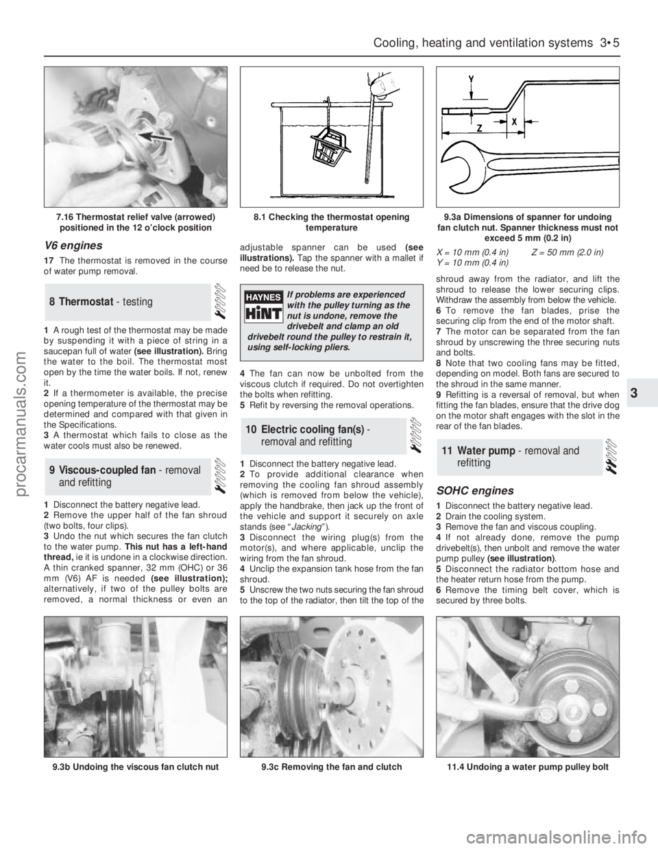
1A rough test of the thermostat may be made
by suspending it with a piece of string in a
saucepan full of water(see illustration).Bring
the water to the boil. The thermostat most
open by the time the water boils. If not, renew
it.
2If a thermometer is available, the precise
opening temperature of the thermostat may be
determined and compared with that given in
the Specifications.
3A thermostat which fails to close as the
water cools must also be renewed.
1Disconnect the battery negative lead.
2Remove the upper half of the fan shroud
(two bolts, four clips).
3Undo the nut which secures the fan clutch
to the water pump.This nut has a left-hand
thread, ie it is undone in a clockwise direction.
A thin cranked spanner, 32 mm (OHC) or 36
mm (V6) AF is needed(see illustration);
alternatively, if two of the pulley bolts are
removed, a normal thickness or even anadjustable spanner can be used (see
illustrations). Tap the spanner with a mallet if
need be to release the nut.
4The fan can now be unbolted from the
viscous clutch if required. Do not overtighten
the bolts when refitting.
5Refit by reversing the removal operations.
1Disconnect the battery negative lead.
2To provide additional clearance when
removing the cooling fan shroud assembly
(which is removed from below the vehicle),
apply the handbrake, then jack up the front of
the vehicle and support it securely on axle
stands (see “Jacking”).
3Disconnect the wiring plug(s) from the
motor(s), and where applicable, unclip the
wiring from the fan shroud.
4Unclip the expansion tank hose from the fan
shroud.
5Unscrew the two nuts securing the fan shroud
to the top of the radiator, then tilt the top of theshroud away from the radiator, and lift the
shroud to release the lower securing clips.
Withdraw the assembly from below the vehicle.
6To remove the fan blades, prise the
securing clip from the end of the motor shaft.
7The motor can be separated from the fan
shroud by unscrewing the three securing nuts
and bolts.
8Note that two cooling fans may be fitted,
depending on model. Both fans are secured to
the shroud in the same manner.
9Refitting is a reversal of removal, but when
fitting the fan blades, ensure that the drive dog
on the motor shaft engages with the slot in the
rear of the fan blades.
SOHC engines
1Disconnect the battery negative lead.
2Drain the cooling system.
3Remove the fan and viscous coupling.
4If not already done, remove the pump
drivebelt(s), then unbolt and remove the water
pump pulley (see illustration).
5Disconnect the radiator bottom hose and
the heater return hose from the pump.
6Remove the timing belt cover, which is
secured by three bolts.
11Water pump - removal and
refitting
10Electric cooling fan(s) -
removal and refitting
9Viscous-coupled fan - removal
and refitting
8Thermostat - testing
Cooling, heating and ventilation systems 3•5
3
7.16 Thermostat relief valve (arrowed)
positioned in the 12 o’clock position8.1 Checking the thermostat opening
temperature9.3a Dimensions of spanner for undoing
fan clutch nut. Spanner thickness must not
exceed 5 mm (0.2 in)
9.3b Undoing the viscous fan clutch nut9.3c Removing the fan and clutch11.4 Undoing a water pump pulley bolt
X = 10 mm (0.4 in)
Y = 10 mm (0.4 in)Z = 50 mm (2.0 in)
If problems are experienced
with the pulley turning as the
nut is undone, remove the
drivebelt and clamp an old
drivebelt round the pulley to restrain it,
using self-locking pliers.
procarmanuals.com
Page 89 of 255
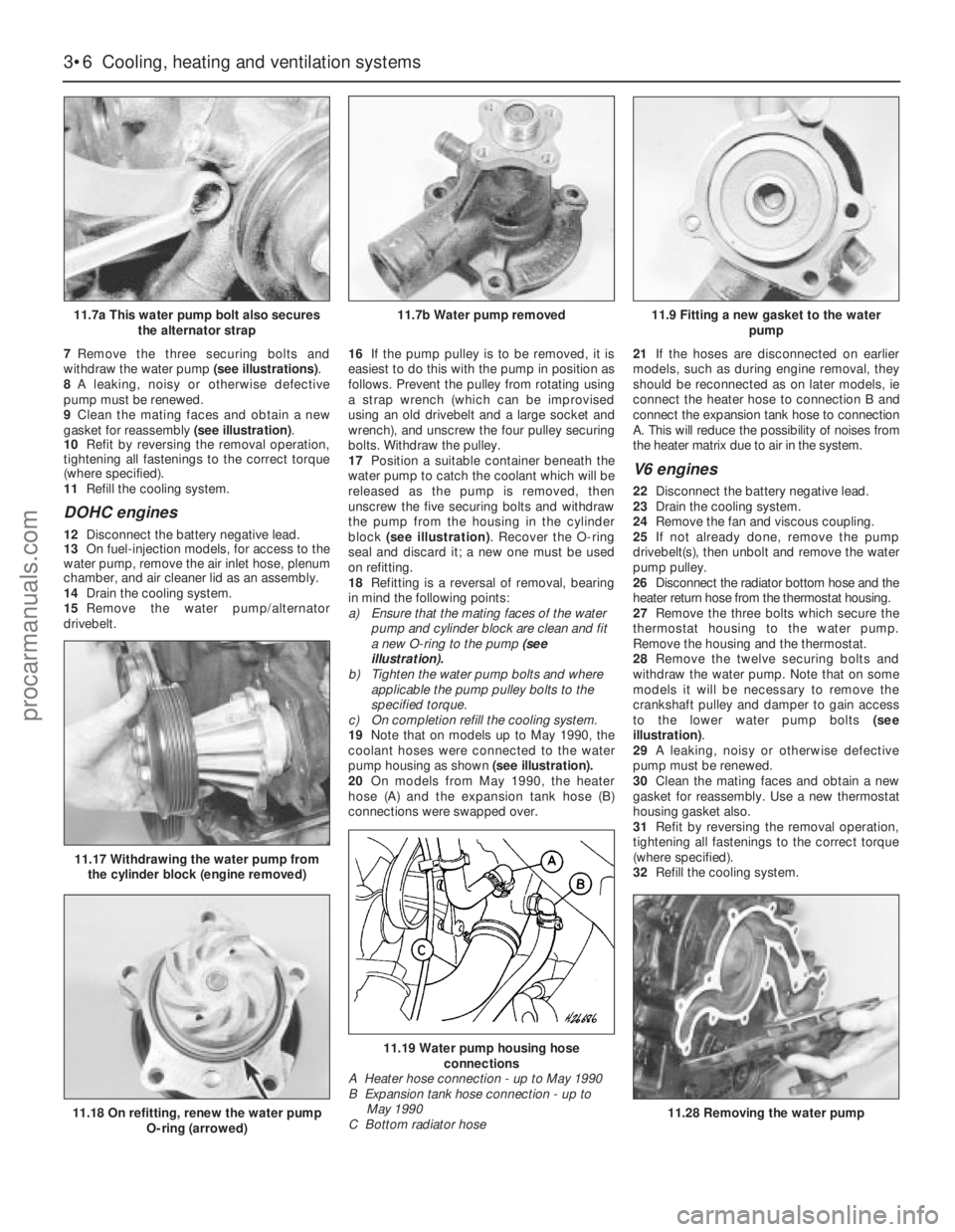
7Remove the three securing bolts and
withdraw the water pump (see illustrations).
8A leaking, noisy or otherwise defective
pump must be renewed.
9Clean the mating faces and obtain a new
gasket for reassembly (see illustration).
10Refit by reversing the removal operation,
tightening all fastenings to the correct torque
(where specified).
11Refill the cooling system.
DOHC engines
12Disconnect the battery negative lead.
13On fuel-injection models, for access to the
water pump, remove the air inlet hose, plenum
chamber, and air cleaner lid as an assembly.
14Drain the cooling system.
15Remove the water pump/alternator
drivebelt.16If the pump pulley is to be removed, it is
easiest to do this with the pump in position as
follows. Prevent the pulley from rotating using
a strap wrench (which can be improvised
using an old drivebelt and a large socket and
wrench), and unscrew the four pulley securing
bolts. Withdraw the pulley.
17Position a suitable container beneath the
water pump to catch the coolant which will be
released as the pump is removed, then
unscrew the five securing bolts and withdraw
the pump from the housing in the cylinder
block (see illustration). Recover the O-ring
seal and discard it; a new one must be used
on refitting.
18Refitting is a reversal of removal, bearing
in mind the following points:
a)Ensure that the mating faces of the water
pump and cylinder block are clean and fit
a new O-ring to the pump (see
illustration).
b)Tighten the water pump bolts and where
applicable the pump pulley bolts to the
specified torque.
c)On completion refill the cooling system.
19Note that on models up to May 1990, the
coolant hoses were connected to the water
pump housing as shown(see illustration).
20On models from May 1990, the heater
hose (A) and the expansion tank hose (B)
connections were swapped over.21If the hoses are disconnected on earlier
models, such as during engine removal, they
should be reconnected as on later models, ie
connect the heater hose to connection B and
connect the expansion tank hose to connection
A. This will reduce the possibility of noises from
the heater matrix due to air in the system.
V6 engines
22Disconnect the battery negative lead.
23Drain the cooling system.
24Remove the fan and viscous coupling.
25If not already done, remove the pump
drivebelt(s), then unbolt and remove the water
pump pulley.
26Disconnect the radiator bottom hose and the
heater return hose from the thermostat housing.
27Remove the three bolts which secure the
thermostat housing to the water pump.
Remove the housing and the thermostat.
28Remove the twelve securing bolts and
withdraw the water pump. Note that on some
models it will be necessary to remove the
crankshaft pulley and damper to gain access
to the lower water pump bolts (see
illustration).
29A leaking, noisy or otherwise defective
pump must be renewed.
30Clean the mating faces and obtain a new
gasket for reassembly. Use a new thermostat
housing gasket also.
31Refit by reversing the removal operation,
tightening all fastenings to the correct torque
(where specified).
32Refill the cooling system.
3•6Cooling, heating and ventilation systems
11.7a This water pump bolt also secures
the alternator strap
11.18 On refitting, renew the water pump
O-ring (arrowed)
11.17 Withdrawing the water pump from
the cylinder block (engine removed)
11.19 Water pump housing hose
connections
A Heater hose connection - up to May 1990
B Expansion tank hose connection - up to
May 1990
C Bottom radiator hose
11.28 Removing the water pump
11.7b Water pump removed11.9 Fitting a new gasket to the water
pump
procarmanuals.com
Page 90 of 255
See Chapter 1, Section 21.
1On 2.0 litre DOHC engines only, remove the
water pump/alternator drivebelt as described
in the previous Section.
2Loosen the alternator lower mounting
through-bolt, then remove the alternator upper
mounting bolt, and swing the alternator away
from the engine.
3Unscrew the central securing bolt, and
withdraw the drivebelt tensioner assembly.
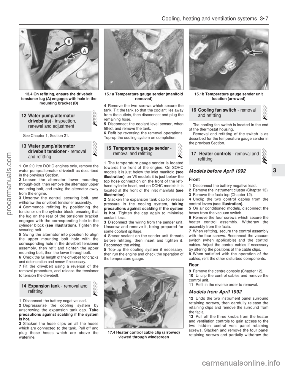
4Commence refitting by positioning the
tensioner on the cylinder block, ensuring that
the lug on the rear of the tensioner bracket
engages with the corresponding hole in the
cylinder block (see illustration). Tighten the
securing bolt.
5Swing the alternator into position to align
the upper mounting bolt hole with the
corresponding hole in the drivebelt tensioner
assembly, then refit and tighten the upper
mounting bolt, then the lower throughbolt.
6Check the full length of the drivebelt for cracks
and deterioration and renew if necessary.
7Fit the drivebelt using a reversal of the
removal procedure, and release the tensioner
to tension the drivebelt.
1Disconnect the battery negative lead.
2Depressurize the cooling system by
unscrewing the expansion tank cap. Take
precautions against scalding if the system
is hot.
3Slacken the hose clips on all the hoses
which are connected to the tank. Pull off and
plug those hoses which are above the
waterline.4Remove the two screws which secure the
tank. Tilt the tank so that the coolant lies away
from the outlets, then disconnect and plug the
remaining hose.
5Disconnect the coolant level sensor, when
fitted, and remove the tank.
6Refit by reversing the removal operations.
Top-up the cooling system on completion.
1The temperature gauge sender is located
towards the front of the engine. On SOHC
models it is just below the inlet manifold (see
illustration); on V6 models it is just below the
top hose connection on the front of the left-
hand cylinder head, and on DOHC models it is
located at the front of the inlet manifold (see
illustration).
2Slacken the expansion tank cap to release
pressure in the cooling system, taking
precautions against scalding if the system
is hot.Tighten the cap again to minimise
coolant loss.
3Disconnect the wiring from the sender unit.
Unscrew and remove it, being prepared for
some coolant spillage.
4Smear sealant on the sender unit threads
before refitting, then insert and tighten it.
Reconnect the wiring.
5Top-up the cooling system if necessary,
then run the engine and check the operation of
the temperature gauge.The cooling fan switch is located in the end
of the thermostat housing.
Removal and refitting of the switch is as
described for the temperature gauge sender in
the previous Section.
Models before April 1992
Front
1Disconnect the battery negative lead.
2Remove the instrument cluster (Chapter 13).
3Remove the facia top (Chapter 12).
4Unclip the two control cables from the
control levers (see illustration).
5On air conditioned models, disconnect the
hoses from the vacuum switch.
6Remove the four screws which secure the
heater control assembly. Withdraw the
assembly from the facia.
7When refitting, secure the control assembly
with the four screws. Reconnect the vacuum
switch (when applicable) and the control
cables. Adjust the control cables if necessary
by altering the positions of the cable clips.
8When satisfied with the operation of the
cables, refit the other disturbed components.
Rear
9Remove the centre console (Chapter 12).
10Unclip the control cables and remove the
control unit.
11Refit in the reverse order to removal.
Models from April 1992
12Undo the two instrument panel surround
retaining screws, then carefully release the
retaining clips and remove the surround from
the facia.
13Pull off the three knobs from the heater
and ventilation controls to gain access to the
two hidden central vent panel retaining
screws. Slacken and remove the four panel
retaining screws and partially withdraw the
17Heater controls - removal and
refitting
16Cooling fan switch - removal
and refitting
15Temperature gauge sender -
removal and refitting
14Expansion tank - removal and
refitting
13Water pump/alternator
drivebelt tensioner - removal
and refitting
12Water pump/alternator
drivebelt(s) - inspection,
renewal and adjustment
Cooling, heating and ventilation systems 3•7
3
13.4 On refitting, ensure the drivebelt
tensioner lug (A) engages with hole in the
mounting bracket (B)15.1a Temperature gauge sender (manifold
removed)15.1b Temperature gauge sender unit
location (arrowed)
17.4 Heater control cable clip (arrowed)
viewed through windscreen
procarmanuals.com
Page 101 of 255
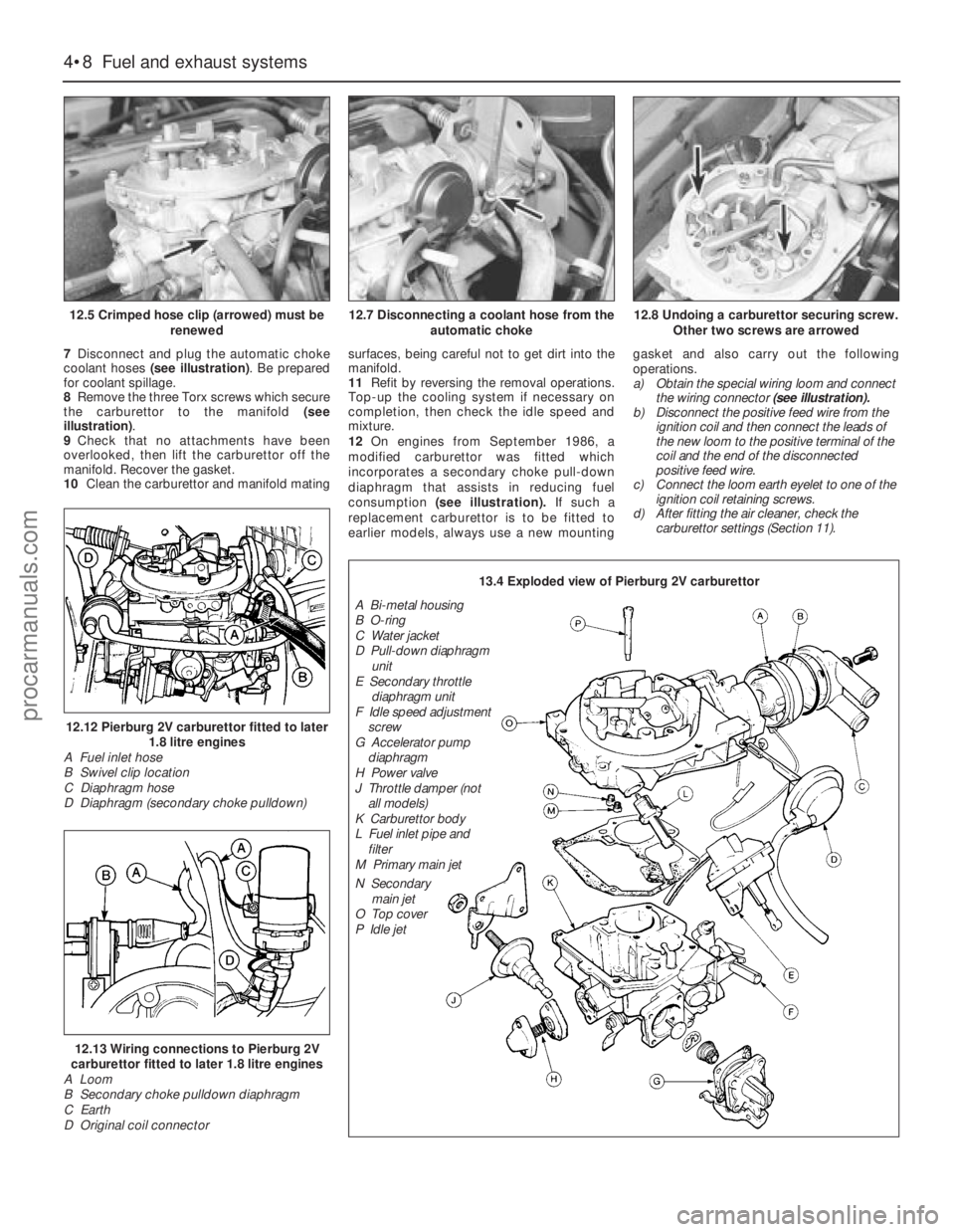
7Disconnect and plug the automatic choke
coolant hoses (see illustration). Be prepared
for coolant spillage.
8Remove the three Torx screws which secure
the carburettor to the manifold (see
illustration).
9Check that no attachments have been
overlooked, then lift the carburettor off the
manifold. Recover the gasket.
10Clean the carburettor and manifold matingsurfaces, being careful not to get dirt into the
manifold.
11Refit by reversing the removal operations.
Top-up the cooling system if necessary on
completion, then check the idle speed and
mixture.
12On engines from September 1986, a
modified carburettor was fitted which
incorporates a secondary choke pull-down
diaphragm that assists in reducing fuel
consumption (see illustration).If such a
replacement carburettor is to be fitted to
earlier models, always use a new mountinggasket and also carry out the following
operations.
a)Obtain the special wiring loom and connect
the wiring connector(see illustration).
b)Disconnect the positive feed wire from the
ignition coil and then connect the leads of
the new loom to the positive terminal of the
coil and the end of the disconnected
positive feed wire.
c)Connect the loom earth eyelet to one of the
ignition coil retaining screws.
d)After fitting the air cleaner, check the
carburettor settings (Section 11).
4•8Fuel and exhaust systems
12.5 Crimped hose clip (arrowed) must be
renewed
12.12 Pierburg 2V carburettor fitted to later
1.8 litre engines
A Fuel inlet hose
B Swivel clip location
C Diaphragm hose
D Diaphragm (secondary choke pulldown)
12.13 Wiring connections to Pierburg 2V
carburettor fitted to later 1.8 litre engines
A Loom
B Secondary choke pulldown diaphragm
C Earth
D Original coil connector
12.7 Disconnecting a coolant hose from the
automatic choke12.8 Undoing a carburettor securing screw.
Other two screws are arrowed
13.4 Exploded view of Pierburg 2V carburettor
A Bi-metal housing
B O-ring
C Water jacket
D Pull-down diaphragm
unit
E Secondary throttle
diaphragm unit
F Idle speed adjustment
screw
G Accelerator pump
diaphragm
H Power valve
J Throttle damper (not
all models)
K Carburettor body
L Fuel inlet pipe and
filter
M Primary main jet
N Secondary
main jet
O Top cover
P Idle jet
procarmanuals.com
Page 114 of 255
55Release the throttle position sensor wiring
connector from the clip under the throttle
body, and separate the two halves of the
connector.
56Remove the fuel-injectors.
57Check that all relevant wiring, hoses and
pipes have been disconnected to facilitate
removal of the manifold.
58Unscrew the ten bolts and two nuts
securing the inlet manifold to the cylinder
head, and carefully withdraw the manifold.
Recover the gasket.
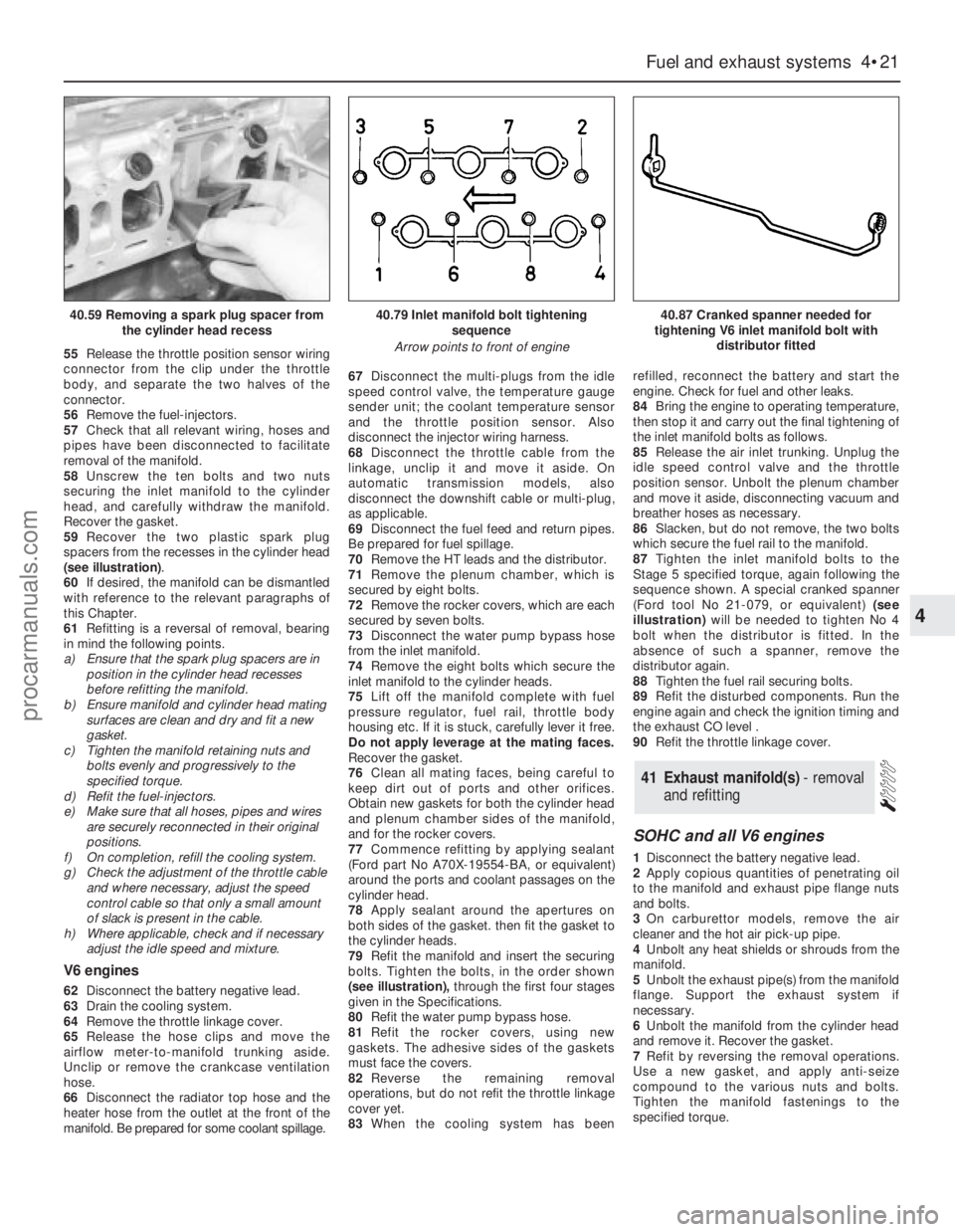
59Recover the two plastic spark plug
spacers from the recesses in the cylinder head
(see illustration).
60If desired, the manifold can be dismantled
with reference to the relevant paragraphs of
this Chapter.
61Refitting is a reversal of removal, bearing
in mind the following points.
a)Ensure that the spark plug spacers are in
position in the cylinder head recesses
before refitting the manifold.
b)Ensure manifold and cylinder head mating
surfaces are clean and dry and fit a new
gasket.
c)Tighten the manifold retaining nuts and
bolts evenly and progressively to the
specified torque.
d)Refit the fuel-injectors.
e)Make sure that all hoses, pipes and wires
are securely reconnected in their original
positions.
f)On completion, refill the cooling system.
g)Check the adjustment of the throttle cable
and where necessary, adjust the speed
control cable so that only a small amount
of slack is present in the cable.
h)Where applicable, check and if necessary
adjust the idle speed and mixture.
V6 engines
62Disconnect the battery negative lead.
63Drain the cooling system.
64Remove the throttle linkage cover.
65Release the hose clips and move the
airflow meter-to-manifold trunking aside.
Unclip or remove the crankcase ventilation
hose.
66Disconnect the radiator top hose and the
heater hose from the outlet at the front of the
manifold. Be prepared for some coolant spillage.67Disconnect the multi-plugs from the idle
speed control valve, the temperature gauge
sender unit; the coolant temperature sensor
and the throttle position sensor. Also
disconnect the injector wiring harness.
68Disconnect the throttle cable from the
linkage, unclip it and move it aside. On
automatic transmission models, also
disconnect the downshift cable or multi-plug,
as applicable.
69Disconnect the fuel feed and return pipes.
Be prepared for fuel spillage.
70Remove the HT leads and the distributor.
71Remove the plenum chamber, which is
secured by eight bolts.
72Remove the rocker covers, which are each
secured by seven bolts.
73Disconnect the water pump bypass hose
from the inlet manifold.
74Remove the eight bolts which secure the
inlet manifold to the cylinder heads.
75Lift off the manifold complete with fuel
pressure regulator, fuel rail, throttle body
housing etc. If it is stuck, carefully lever it free.
Do not apply leverage at the mating faces.
Recover the gasket.
76Clean all mating faces, being careful to
keep dirt out of ports and other orifices.
Obtain new gaskets for both the cylinder head
and plenum chamber sides of the manifold,
and for the rocker covers.
77Commence refitting by applying sealant
(Ford part No A70X-19554-BA, or equivalent)
around the ports and coolant passages on the
cylinder head.
78Apply sealant around the apertures on
both sides of the gasket. then fit the gasket to
the cylinder heads.
79Refit the manifold and insert the securing
bolts. Tighten the bolts, in the order shown
(see illustration),through the first four stages
given in the Specifications.
80Refit the water pump bypass hose.
81Refit the rocker covers, using new
gaskets. The adhesive sides of the gaskets
must face the covers.
82Reverse the remaining removal
operations, but do not refit the throttle linkage
cover yet.
83When the cooling system has beenrefilled, reconnect the battery and start the
engine. Check for fuel and other leaks.
84Bring the engine to operating temperature,
then stop it and carry out the final tightening of
the inlet manifold bolts as follows.
85Release the air inlet trunking. Unplug the
idle speed control valve and the throttle
position sensor. Unbolt the plenum chamber
and move it aside, disconnecting vacuum and
breather hoses as necessary.
86Slacken, but do not remove, the two bolts
which secure the fuel rail to the manifold.
87Tighten the inlet manifold bolts to the
Stage 5 specified torque, again following the
sequence shown. A special cranked spanner
(Ford tool No 21-079, or equivalent)(see
illustration)will be needed to tighten No 4
bolt when the distributor is fitted. In the
absence of such a spanner, remove the
distributor again.
88Tighten the fuel rail securing bolts.
89Refit the disturbed components. Run the
engine again and check the ignition timing and
the exhaust CO level .
90Refit the throttle linkage cover.
SOHC and all V6 engines
1Disconnect the battery negative lead.
2Apply copious quantities of penetrating oil
to the manifold and exhaust pipe flange nuts
and bolts.
3On carburettor models, remove the air
cleaner and the hot air pick-up pipe.
4Unbolt any heat shields or shrouds from the
manifold.
5Unbolt the exhaust pipe(s) from the manifold
flange. Support the exhaust system if
necessary.
6Unbolt the manifold from the cylinder head
and remove it. Recover the gasket.
7Refit by reversing the removal operations.
Use a new gasket, and apply anti-seize
compound to the various nuts and bolts.
Tighten the manifold fastenings to the
specified torque.
41Exhaust manifold(s) - removal
and refitting
Fuel and exhaust systems 4•21
4
40.59 Removing a spark plug spacer from
the cylinder head recess40.79 Inlet manifold bolt tightening
sequence
Arrow points to front of engine40.87 Cranked spanner needed for
tightening V6 inlet manifold bolt with
distributor fitted
procarmanuals.com
Page 120 of 255
engine coolant temperature sensor. The
crankshaft speed/position sensor is activated
by a toothed disc on the rear of the crankshaft,
inside the cylinder block. The disc has 35
equally spaced teeth (one every 10°), with a
gap in the 36th position. The gap is used by
the sensor to determine the crankshaft
position relative to Top Dead Centre (TDC) of
No 1 piston.
The ignition advance is a function of the
ESC II module, and is controlled by vacuum.
The module is connected to the carburettor by
a vacuum pipe, and a transducer in the
module translates the vacuum signal into an
electrical voltage. From the vacuum signal, the
module determines engine load; engine speed
and temperature are determined from the
crankshaft speed/position sensor and the
engine coolant temperature sensor. The
module has a range of spark advance settings
stored in the memory, and a suitable setting is
selected for the relevant engine speed, load
and temperature. The degree of advance can
thus be constantly varied to suit the prevailing
engine speed and load conditions.
On DOHC fuel-injected engines, a
development of the EEC IV (Electronic Engine
Control IV) engine management system is
used to control both the ignition and fuel-
injection systems. The EEC IV module receives
information from a crankshaft speed/position
sensor (the same as that fitted to the
carburettor models), a throttle position sensor,
an engine coolant temperature sensor, a fuel
temperature sensor, an air charge temperature
sensor, a Manifold Absolute Pressure (MAP)
sensor, and a vehicle speed sensor (mounted
on the gearbox). Additionally, on models with
a catalytic converter, an additional input is
supplied to the EEC IV module from an
exhaust gas oxygen (HEGO) sensor. On
models with automatic transmission,
additional sensors are fitted to the
transmission to inform the EEC IV module
when the transmission is in neutral, and when
the downshift is being operated.
The module provides outputs to control the
fuel pump, fuel-injectors, idle speed, ignition
system and automatic transmission .
Additionally, on models with air conditioning,
the EEC IV module disengages the air
conditioning compressor clutch when starting
the engine or when the engine is suddenly
accelerated. On models fitted with a catalytic
converter, the EEC IV module also controls the
carbon canister purge solenoid valve.
Using the inputs from the various sensors,
the EEC IV module computes the optimum
ignition advance, and fuel-injector pulse
duration to suit the prevailing engine
conditions.
On 2.4 & 2.9 litre V6 engines, the system
operates in much the same way as that fitted
to the DOHC fuel-injected engine, noting the
following points.
a)There is no crankshaft speed/position
sensor.
b)The vehicle speed sensor is only fitted to
models equipped with a catalytic
converter.Precautions
ESC II module
Although it will tolerate all normal under-
bonnet conditions, the ESC II module may be
adversely affected by water entry during
steam cleaning or pressure washing of the
engine bay.
If cleaning the engine bay, therefore, take
care not to direct jets of water or steam at the
ESC II module. If this cannot be avoided,
remove the module completely, and protect its
multi-plug with a plastic bag.
Ignition system HT voltage
Take care to avoid receiving electric shocks
from the HT side of the ignition system. Do not
handle HT leads, or touch the distributor or
coil, when the engine is running. When tracing
faults in the HT system, use well insulated
tools to manipulate live leads. Electronic
ignition HT voltage could prove fatal.
Electronic ignition systems
General
Further details of the various systems are
given in the relevant Sections of this Chapter.
While some repair procedures are given, the
usual course of action is to renew the
component concerned. The owner whose
interest extends beyond mere component
renewal should obtain a copy of the
Automobile Electrical & Electronic Systems
Manual, available from the publishers of this
manual.
It is necessary to take extra care when
working on the electrical system, to avoid
damage to semi-conductor devices (diodes
and transistors), and to avoid the risk of
personal injury. In addition to the precautions
given in Safety first!at the beginning of this
manual, observe the following when working
on the system:
Always remove rings, watches, etc before
working on the electrical system.Even with the
battery disconnected, capacitive discharge
could occur if a component’s live terminal is
earthed through a metal object. This could
cause a shock or nasty burn.
Do not reverse the battery connections.
Components such as the alternator, electronic
control units, or any other components having
semi-conductor circuitry, could be irreparably
damaged.
If the engine is being started using jump
leads and a slave battery, connect thebatteries positive-to-positiveand negative-to-
negative(see “Jump starting”). This also
applies when connecting a battery charger.
Never disconnect the battery terminals, the
alternator, any electrical wiring, or any test
instruments, when the engine is running.
Do not allow the engine to turn the alternator
when the alternator is not connected.
Never test for alternator output by “flashing”
the output lead to earth.
Never use an ohmmeter of the type
incorporating a hand-cranked generator for
circuit or continuity testing.
Always ensure that the battery negative lead
is disconnected when working on the
electrical system.
Before using electric-arc welding equipment
on the car, disconnect the battery, alternator,
and components such as the fuel-
injection/ignition electronic control unit, to
protect them from the risk of damage.
Refer to Chapter 13
1In normal use the battery should not require
charging from an external source, unless the
vehicle is laid up for long periods, when it
should be recharged every six weeks or so. If
vehicle use consists entirely of short runs in
darkness it is also possible for the battery to
become discharged. Otherwise, a regular
need for recharging points to a fault in the
battery or elsewhere in the charging system.
2There is no need to disconnect the battery
from the vehicle wiring when using a battery
charger, but switch off the ignition and leave
the bonnet open.
3Domestic battery chargers (up to about 6
amps output) may safely be used overnight
without special precautions. Make sure that
the charger is set to deliver 12 volts before
connecting it. Connect the leads (red or
positive to the positive terminal, black or
negative to the negative terminal) before
switching the charger on at the mains.
4When charging is complete, switch off at
the mains beforedisconnecting the charger
from the battery. Remember that the battery
will be giving off hydrogen gas, which is
potentially explosive.
5Charging at a higher rate should only be
carried out under carefully controlled
conditions. Very rapid or “boost” charging
should be avoided if possible, as it is liable to
cause permanent damage to the battery
through overheating.
6During any sort of charging, battery
electrolyte temperature should never exceed
38°C (100°F). If the battery becomes hot, or
the electrolyte is effervescing vigorously,
charging should be stopped.
3Battery - charging
2Electrical fault-finding - general
information
Engine electrical systems 5•3
5
Warning. The voltages produced
by the electronic ignition system
are considerably higher than those
produced by conventional
systems. Extreme care must be taken when
working on the system with the ignition
switched on. Persons with surgically-
implanted cardiac pacemaker devices
should keep well clear of the ignition
circuits, components and test equipment.
procarmanuals.com