1985 FORD GRANADA washer fluid
[x] Cancel search: washer fluidPage 49 of 255
Note: Refer to Part A, Section 4 of this Chapter
and to the warning that appears at the start of
Section 5 before proceeding. A hoist and lifting
tackle will be required for this operation.
1Proceed as described in paragraphs 1 to 21
of Section 5.
2Unscrew the securing bolt, and disconnect
the earth lead from the rear left-hand side of
the cylinder head.
3Unscrew the nuts securing the engine
mountings to the engine mounting brackets.
4Jack up the vehicle and support it securely
on axle stands (see “Jacking”). Ensure that
there is enough working room beneath the
vehicle.
5To improve access, disconnect the exhaust
downpipe from the manifold and remove the
exhaust system.
6Drain the engine oil into a suitable container.
7On models fitted with a catalytic converter,
release the securing clips and withdraw the
exhaust heat shield from under the vehicle for
access to the propeller shaft.
8Remove the propeller shaft.
9Where applicable, bend back the locktabs,
then unscrew the two bolts in each case
securing the two anti-roll bar mounting clamps
to the vehicle underbody. Lower the anti-roll
bar as far as possible.
10Proceed as described in paragraphs 30
and 31 of Section 5.
11Support the gearbox with a trolley jack,
using a block of wood between the jack and
the gearbox to spread the load.
12Unscrew the four nuts securing the
gearbox crossmember to the vehicle
underbody. Unscrew the central bolt securing
the crossmember to the gearbox, and remove
the crossmember. Note the position of the
earth strap, where applicable. Recover the
mounting cup, and the exhaust mounting
bracket and heat shield (as applicable).
13Lower the gearbox slightly on the jack,
then remove the circlip, and disconnect the
speedometer drive cable from the gearbox.
14Disconnect the wiring from the reversing
lamp switch, and on models with fuel-injection,
disconnect the wiring from the vehicle speed
sensor mounted in the side of the gearbox.
15Slacken and remove the two bolts and
washers (one either side) securing the gear
linkage support bracket to the gearbox.
16Using a pin punch, drive out the roll pin
securing the gearchange rod to the gear linkage.
17Attach a hoist to the engine lifting brackets
located at the front and rear of the cylinder head,
and slowly take the weight of the engine. Arrange
the lifting tackle so that the engine/gearbox
assembly will assume a steep angle of
approximately 40°to 45°as it is being removed.
18To improve clearance in the engine
compartment when lifting the engine, unboltthe engine mounting brackets from the
cylinder block, and remove them.
19Ensure that the steering wheel is positioned
in the straight-ahead position then, using a dab
of paint or a marker pen, make alignment marks
between the intermediate shaft lower clamp
and steering gear pinion. Slacken and remove
the lower clamp bolt then disconnect the
intermediate shaft from the steering gear.
20Detach the brake lines from the front
suspension crossmember.
21Support the crossmember with a jack (do not
remove the jack from under the gearbox), then
loosen the bolts securing the crossmember to the
underbody. Remove the crossmember securing
bolts, and carefully lower the crossmember to
allow sufficient room for the engine sump to clear
the steering rack and crossmember as the
engine/gearbox assembly is removed.
22Make a final check to ensure that all
relevant wires, pipes and hoses have been
disconnected to facilitate removal of the
engine/gearbox assembly.
23Raise the engine/gearbox, at the same
time lowering the trolley jack which is
supporting the gearbox.
24Place a suitable rod across the vehicle
underbody to support the gear linkage support
bracket whilst the gearbox is removed.
25Tilt the engine/gearbox assembly using
the hoist and the trolley jack, until the
assembly can be lifted from the vehicle. Take
care not to damage surrounding components.
26If the vehicle is to be moved, with the
engine/gearbox assembly removed, temporarily
refit the suspension crossmember and the anti-
roll bar to the underbody, and reconnect the
steering column to the intermediate shaft.
27To separate the engine from the gearbox,
proceed as follows.
28Remove the starter motor.
29Support the engine and gearbox
horizontally on blocks of wood.
30Unscrew the engine-to-gearbox bolts,
noting the locations of the bolts, and the
positions of the earth strap and any wiring clips
attached to the bolts. Recover any shims fitted
between the sump and the gearbox when
removing the lower engine-to-gearbox bolts.
31Unscrew the bolt from the engine adapter
plate.
32Pull the engine and gearbox apart, taking
care not to strain the gearbox input shaft. It
may be necessary to rock the units slightly to
separate them.
Note: Refer to Part A, Section 4 of this
Chapter and to the warning that appears at the
start of Section 5 before proceeding. A
suitable hoist and lifting tackle will be required
for this operation. Any suspected faults in the
automatic transmission should be referred to a
Ford dealer or automatic transmissionspecialist before removal of unit, as the
specialist fault diagnosis equipment is
designed to operate with the transmission in
the vehicle.
1Proceed as described in paragraphs 1 to 21
of Section 5.
2Unscrew the securing bolt, and disconnect
the earth lead from the rear left-hand side of
the cylinder head.
3Unscrew the nuts securing the engine
mountings to the engine mounting brackets.
4Jack up the vehicle and support it securely
on axle stands (see “Jacking”). Ensure that
there is enough working room beneath the
vehicle.
5To improve access, disconnect the exhaust
downpipe from the manifold and remove the
exhaust system .
6Drain the engine oil into a suitable container.
7On models fitted with a catalytic converter,
release the securing clips and withdraw the
exhaust heat shield from under the vehicle for
access to the propeller shaft.
8Remove the propeller shaft.
9Where applicable, bend back the locktabs,
then unscrew the two bolts in each case
securing the two anti-roll bar mounting clamps
to the vehicle underbody. Lower the anti-roll
bar as far as possible.
10Support the transmission with a trolley
jack, using a block of wood between the jack
and the transmission to spread the load.
11Unscrew the four bolts securing the
transmission crossmember to the vehicle
underbody. Unscrew the central bolt securing
the crossmember to the transmission, and
remove the crossmember. Note the position of
the earth strap, where applicable. Recover the
mounting cup, and the exhaust mounting
bracket and heat shield (as applicable).
12Lower the transmission slightly on the jack.
13Unscrew the unions and disconnect the
fluid cooler pipes from the transmission. Plug
the open ends of the pipes and the
transmission to prevent dirt ingress and fluid
leakage. Where applicable, detach the fluid
cooler pipe bracket from the engine mounting
bracket, and move it to one side.
14Remove the two clips securing the
selector rod, and detach the selector rod from
the manual selector lever, and the selector
lever on the transmission.
15Disconnect the wiring from the starter
inhibitor switch, downshift solenoid, lock-up
clutch, reversing lamp switch, and where
applicable, the 3rd/4th gearchange solenoid.
16Remove the securing screw, and
disconnect the speedometer cable (where
fitted) from the transmission extension
housing. Plug the opening in the transmission
to prevent dirt ingress.
17Proceed as described in paragraphs 17 to 26
of Section 7, substituting transmission for
gearbox and ignoring paragraph 24.
18To separate the engine from the
transmission, proceed as follows.
19Remove the starter motor.
20Support the engine and transmission
horizontally on blocks of wood.
8Engine/automatic
transmission assembly -
removal and separation
7Engine/manual gearbox
assembly - removal and
separation
2B•6DOHCengine
procarmanuals.com
Page 135 of 255
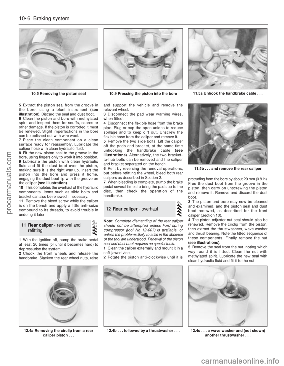
5Extract the piston seal from the groove in
the bore, using a blunt instrument (see
illustration). Discard the seal and dust boot.
6Clean the piston and bore with methylated
spirit and inspect them for scuffs, scores or
other damage. If the piston is corroded it must
be renewed. Slight imperfections in the bore
can be polished out with wire wool.
7Place the clean component on a clean
surface ready for reassembly. Lubricate the
caliper hose with clean hydraulic fluid.
8Fit the new piston seal to the groove in the
bore, using fingers only to work it into position.
9Lubricate the piston with clean hydraulic
fluid and fit the dust boot over the piston,
making sure it is the right way up. Insert the
piston into the bore and press it home,
engaging the dust boot lip with the groove on
the caliper (see illustration).
10This completes the overhaul of the hydraulic
components. Items such as slide bolts and
bracket can also be renewed if necessary.
11Remove the bleed screw while the caliper
is on the bench and apply a little anti-seize
compound to its threads, to avoid trouble in
undoing it later.
1With the ignition off, pump the brake pedal
at least 20 times (or until it becomes hard) to
depressurise the system.
2Chock the front wheels and release the
handbrake. Slacken the rear wheel nuts, raiseand support the vehicle and remove the
relevant wheel.
3Disconnect the pad wear warning wires,
when fitted.
4Disconnect the flexible hose from the brake
pipe. Plug or cap the open unions to reduce
spillage and to keep dirt out. Unscrew the
flexible hose from the caliper and remove it.
5Remove the two slide bolts. Lift the caliper
off the pads and bracket, at the same time
unhooking the handbrake cable (see
illustrations). Alternatively, the two bracket-
to-hub bolts can be removed and the caliper
and bracket separated on the bench.
6Refit by reversing the removal operations,
but before refitting the wheel, bleed both rear
calipers as described in Section 2.
7When bleeding is complete, pump the brake
pedal several times to bring the pads up to the
disc, then check the operation of the
handbrake.
Note: Complete dismantling of the rear caliper
should not be attempted unless Ford spring
compressor (tool No 12-007) is available. or
unless the problems likely to arise in the absence
of the tool are understood. Renewal of the piston
seal and dust boot requires no special tools.
1Clean the caliper externally and mount it in a
soft-jawed vice.
2Rotate the piston anti-clockwise until it isprotruding from the bore by about 20 mm (0.8 in).
Free the dust boot from the groove in the
piston, then carry on unscrewing the piston
and remove it. Remove and discard the dust
boot.
3The piston and bore may now be cleaned
and examined, and the piston seal and dust
boot renewed, as described for the front
caliper (Section 10).
4The piston adjuster nut seal should also be
renewed. Remove the circlip from the piston,
then extract the thrustwashers, wave washer
and thrust bearing. Note the fitted sequence of
these components. Finally remove the nut
(see illustrations).
5Remove the seal from the nut, noting which
way round it is fitted. Clean the nut with
methylated spirit. Lubricate the new seal with
clean hydraulic fluid and fit it to the nut.
12Rear caliper - overhaul
11Rear caliper - removal and
refitting
10•6Braking system
10.5 Removing the piston seal
12.4a Removing the circlip from a rear
caliper piston . . .12.4b . . . followed by a thrustwasher . . .
11.5b . . . and remove the rear caliper
10.9 Pressing the piston into the bore11.5a Unhook the handbrake cable . . .
12.4c . . . a wave washer and (not shown)
another thrustwasher . . .
procarmanuals.com
Page 137 of 255
17Refit the washer, spring and spring cover.
Compress the spring and refit the circlip, then
release the spring compressor.
18Lubricate the caliper bore with clean
hydraulic fluid and fit a new piston seal.
19Reassemble the piston components.
Lubricate the contact face of the adjuster nut
with a little brake grease, then fit the adjuster
nut (with new seal), thrust bearing,
thrustwasher, wave washer and the second
thrustwasher. Secure with the circlip.
20Fit a new dust boot. The manufacturers
recommend that it be fitted to the caliper
groove and the piston fitted afterwards; it is
also possible to fit the boot to the piston first
and engage it in the caliper groove afterwards.
Either way it is a fiddly business.
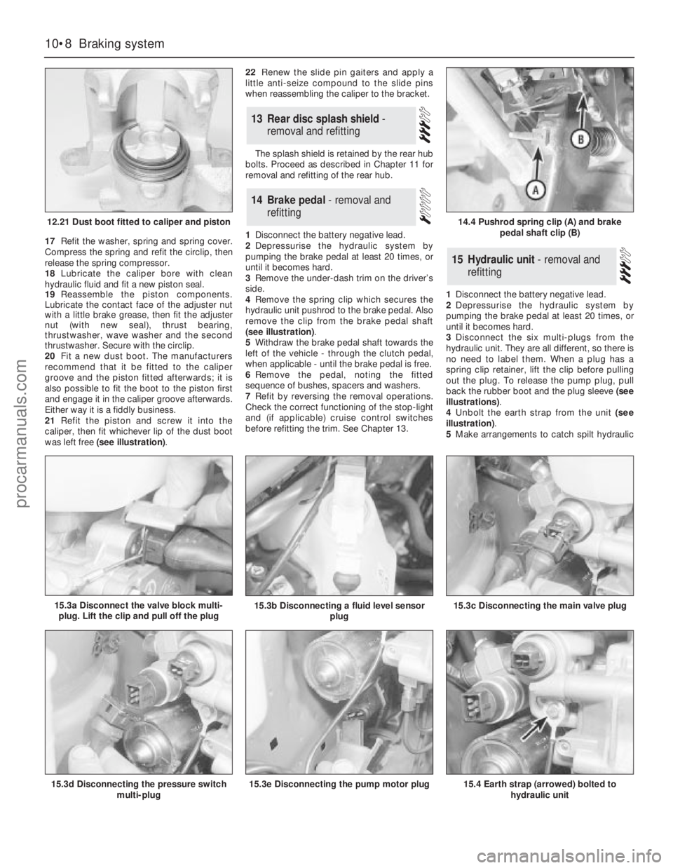
21Refit the piston and screw it into the
caliper, then fit whichever lip of the dust boot
was left free (see illustration).22Renew the slide pin gaiters and apply a
little anti-seize compound to the slide pins
when reassembling the caliper to the bracket.
The splash shield is retained by the rear hub
bolts. Proceed as described in Chapter 11 for
removal and refitting of the rear hub.
1Disconnect the battery negative lead.
2Depressurise the hydraulic system by
pumping the brake pedal at least 20 times, or
until it becomes hard.
3Remove the under-dash trim on the driver’s
side.
4Remove the spring clip which secures the
hydraulic unit pushrod to the brake pedal. Also
remove the clip from the brake pedal shaft
(see illustration).
5Withdraw the brake pedal shaft towards the
left of the vehicle - through the clutch pedal,
when applicable - until the brake pedal is free.
6Remove the pedal, noting the fitted
sequence of bushes, spacers and washers.
7Refit by reversing the removal operations.
Check the correct functioning of the stop-light
and (if applicable) cruise control switches
before refitting the trim. See Chapter 13.1Disconnect the battery negative lead.
2Depressurise the hydraulic system by
pumping the brake pedal at least 20 times, or
until it becomes hard.
3Disconnect the six multi-plugs from the
hydraulic unit. They are all different, so there is
no need to label them. When a plug has a
spring clip retainer, lift the clip before pulling
out the plug. To release the pump plug, pull
back the rubber boot and the plug sleeve (see
illustrations).
4Unbolt the earth strap from the unit (see
illustration).
5Make arrangements to catch spilt hydraulic
15Hydraulic unit - removal and
refitting
14Brake pedal - removal and
refitting
13Rear disc splash shield -
removal and refitting
10•8Braking system
12.21 Dust boot fitted to caliper and piston
15.3d Disconnecting the pressure switch
multi-plug15.3e Disconnecting the pump motor plug15.4 Earth strap (arrowed) bolted to
hydraulic unit
14.4 Pushrod spring clip (A) and brake
pedal shaft clip (B)
15.3a Disconnect the valve block multi-
plug. Lift the clip and pull off the plug15.3b Disconnecting a fluid level sensor
plug15.3c Disconnecting the main valve plug
procarmanuals.com
Page 139 of 255
1Remove the accumulator (Section 17).
2Disconnect the high pressure hose from the
pump. Be prepared for fluid spillage.
3Disconnect the low pressure hose from the
pump. Allow the fluid to drain out of the
reservoir through the hose.
4Disconnect the multi-plugs from the
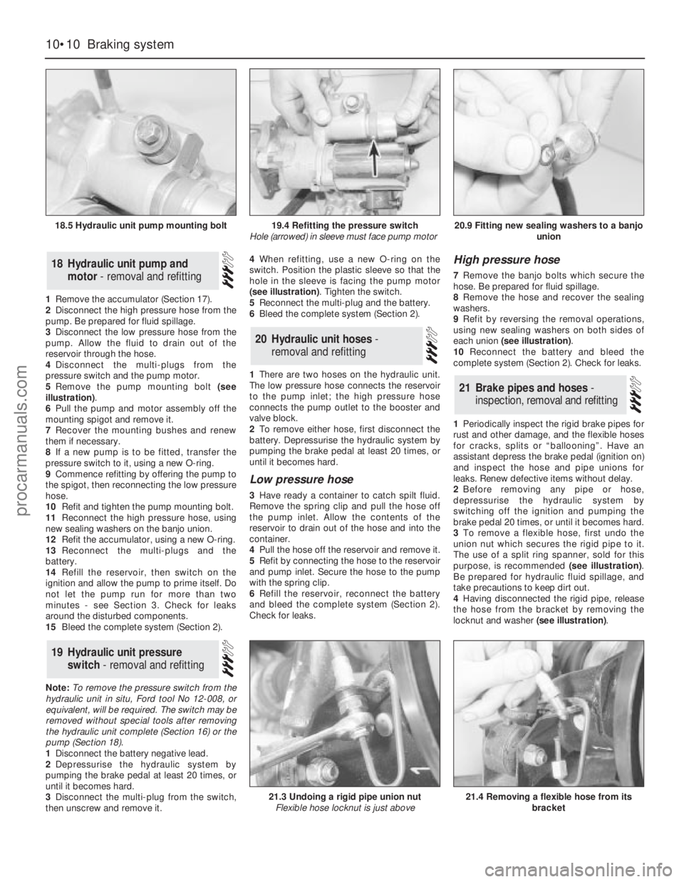
pressure switch and the pump motor.
5Remove the pump mounting bolt (see
illustration).
6Pull the pump and motor assembly off the
mounting spigot and remove it.
7Recover the mounting bushes and renew
them if necessary.
8If a new pump is to be fitted, transfer the
pressure switch to it, using a new O-ring.
9Commence refitting by offering the pump to
the spigot, then reconnecting the low pressure
hose.
10Refit and tighten the pump mounting bolt.
11Reconnect the high pressure hose, using
new sealing washers on the banjo union.
12Refit the accumulator, using a new O-ring.
13Reconnect the multi-plugs and the
battery.
14Refill the reservoir, then switch on the
ignition and allow the pump to prime itself. Do
not let the pump run for more than two
minutes - see Section 3. Check for leaks
around the disturbed components.
15Bleed the complete system (Section 2).
Note: To remove the pressure switch from the
hydraulic unit in situ, Ford tool No 12-008, or
equivalent, will be required. The switch may be
removed without special tools after removing
the hydraulic unit complete (Section 16) or the
pump (Section 18).
1Disconnect the battery negative lead.
2Depressurise the hydraulic system by
pumping the brake pedal at least 20 times, or
until it becomes hard.
3Disconnect the multi-plug from the switch,
then unscrew and remove it.4When refitting, use a new O-ring on the
switch. Position the plastic sleeve so that the
hole in the sleeve is facing the pump motor
(see illustration). Tighten the switch.
5Reconnect the multi-plug and the battery.
6Bleed the complete system (Section 2).
1There are two hoses on the hydraulic unit.
The low pressure hose connects the reservoir
to the pump inlet; the high pressure hose
connects the pump outlet to the booster and
valve block.
2To remove either hose, first disconnect the
battery. Depressurise the hydraulic system by
pumping the brake pedal at least 20 times, or
until it becomes hard.
Low pressure hose
3Have ready a container to catch spilt fluid.
Remove the spring clip and pull the hose off
the pump inlet. Allow the contents of the
reservoir to drain out of the hose and into the
container.
4Pull the hose off the reservoir and remove it.
5Refit by connecting the hose to the reservoir
and pump inlet. Secure the hose to the pump
with the spring clip.
6Refill the reservoir, reconnect the battery
and bleed the complete system (Section 2).
Check for leaks.
High pressure hose
7Remove the banjo bolts which secure the
hose. Be prepared for fluid spillage.
8Remove the hose and recover the sealing
washers.
9Refit by reversing the removal operations,
using new sealing washers on both sides of
each union (see illustration).
10Reconnect the battery and bleed the
complete system (Section 2). Check for leaks.
1Periodically inspect the rigid brake pipes for
rust and other damage, and the flexible hoses
for cracks, splits or “ballooning”. Have an
assistant depress the brake pedal (ignition on)
and inspect the hose and pipe unions for
leaks. Renew defective items without delay.
2Before removing any pipe or hose,
depressurise the hydraulic system by
switching off the ignition and pumping the
brake pedal 20 times, or until it becomes hard.
3To remove a flexible hose, first undo the
union nut which secures the rigid pipe to it.
The use of a split ring spanner, sold for this
purpose, is recommended (see illustration).
Be prepared for hydraulic fluid spillage, and
take precautions to keep dirt out.
4Having disconnected the rigid pipe, release
the hose from the bracket by removing the
locknut and washer (see illustration).
21Brake pipes and hoses -
inspection, removal and refitting
20Hydraulic unit hoses -
removal and refitting
19Hydraulic unit pressure
switch - removal and refitting
18Hydraulic unit pump and
motor - removal and refitting
10•10Braking system
18.5 Hydraulic unit pump mounting bolt
21.3 Undoing a rigid pipe union nut
Flexible hose locknut is just above21.4 Removing a flexible hose from its
bracket
19.4 Refitting the pressure switch
Hole (arrowed) in sleeve must face pump motor20.9 Fitting new sealing washers to a banjo
union
procarmanuals.com
Page 161 of 255
Where serious damage has occurred or
large areas need renewal due to neglect, it
means certainly that completely new sections
or panels will need welding in and this is best
left to professionals. If the damage is due to
impact, it will also be necessary to completely
check the alignment of the bodyshell
structure. Due to the principle of construction,
the strength and shape of the whole car can
be affected by damage to one part. In such
instances the services of a Ford agent with
specialist checking jigs are essential. If a body
is left misaligned, it is first of all dangerous as
the car will not handle properly, and secondly
uneven stresses will be imposed on the
steering, engine and transmission, causing
abnormal wear or complete failure. Tyre wear
may also be excessive.
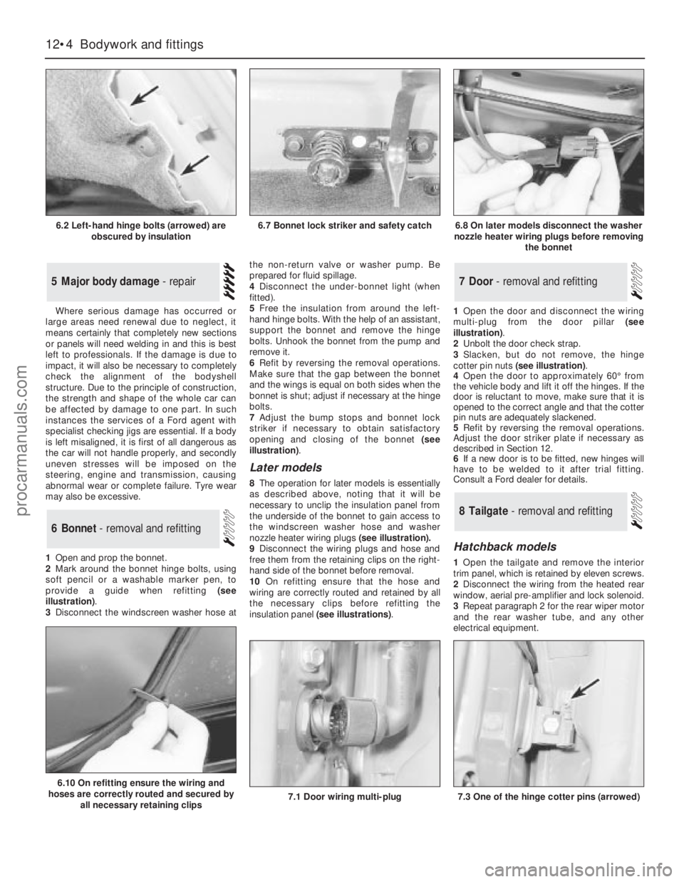
1Open and prop the bonnet.
2Mark around the bonnet hinge bolts, using
soft pencil or a washable marker pen, to
provide a guide when refitting (see
illustration).
3Disconnect the windscreen washer hose atthe non-return valve or washer pump. Be
prepared for fluid spillage.
4Disconnect the under-bonnet light (when
fitted).
5Free the insulation from around the left-
hand hinge bolts. With the help of an assistant,
support the bonnet and remove the hinge
bolts. Unhook the bonnet from the pump and
remove it.
6Refit by reversing the removal operations.
Make sure that the gap between the bonnet
and the wings is equal on both sides when the
bonnet is shut; adjust if necessary at the hinge
bolts.
7Adjust the bump stops and bonnet lock
striker if necessary to obtain satisfactory
opening and closing of the bonnet (see
illustration).
Later models
8The operation for later models is essentially
as described above, noting thatit will be
necessary to unclip the insulation panel from
the underside of the bonnet to gain access to
the windscreen washer hose and washer
nozzle heater wiring plugs (see illustration).
9Disconnect the wiring plugs and hose and
free them from the retaining clips on the right-
hand side of the bonnet before removal.
10On refitting ensure that the hose and
wiring are correctly routed and retained by all
the necessary clips before refitting the
insulation panel (see illustrations).1Open the door and disconnect the wiring
multi-plug from the door pillar (see
illustration).
2Unbolt the door check strap.
3Slacken, but do not remove, the hinge
cotter pin nuts (see illustration).
4Open the door to approximately 60°from
the vehicle body and lift it off the hinges. If the
door is reluctant to move, make sure that it is
opened to the correct angle and that the cotter
pin nuts are adequately slackened.
5Refit by reversing the removal operations.
Adjust the door striker plate if necessary as
described in Section 12.
6If a new door is to be fitted, new hinges will
have to be welded to it after trial fitting.
Consult a Ford dealer for details.
Hatchback models
1Open the tailgate and remove the interior
trim panel, which is retained by eleven screws.
2Disconnect the wiring from the heated rear
window, aerial pre-amplifier and lock solenoid.
3Repeat paragraph 2 for the rear wiper motor
and the rear washer tube, and any other
electrical equipment.
8Tailgate - removal and refitting
7Door - removal and refitting
6Bonnet - removal and refitting
5Major body damage - repair
12•4Bodywork and fittings
6.2 Left-hand hinge bolts (arrowed) are
obscured by insulation
6.10 On refitting ensure the wiring and
hoses are correctly routed and secured by
all necessary retaining clips
7.1 Door wiring multi-plug7.3 One of the hinge cotter pins (arrowed)
6.7 Bonnet lock striker and safety catch6.8 On later models disconnect the washer
nozzle heater wiring plugs before removing
the bonnet
procarmanuals.com
Page 193 of 255
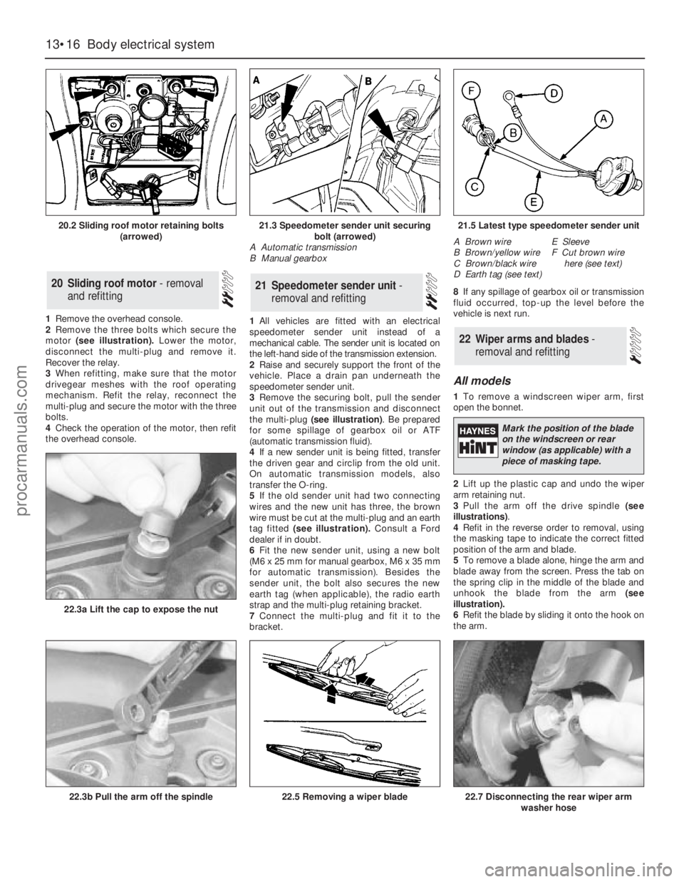
1Remove the overhead console.
2Remove the three bolts which secure the
motor (see illustration).Lower the motor,
disconnect the multi-plug and remove it.
Recover the relay.
3When refitting, make sure that the motor
drivegear meshes with the roof operating
mechanism. Refit the relay, reconnect the
multi-plug and secure the motor with the three
bolts.
4Check the operation of the motor, then refit
the overhead console.1All vehicles are fitted with an electrical
speedometer sender unit instead of a
mechanical cable. The sender unit is located on
the left-hand side of the transmission extension.
2Raise and securely support the front of the
vehicle. Place a drain pan underneath the
speedometer sender unit.
3Remove the securing bolt, pull the sender
unit out of the transmission and disconnect
the multi-plug (see illustration). Be prepared
for some spillage of gearbox oil or ATF
(automatic transmission fluid).
4If a new sender unit is being fitted, transfer
the driven gear and circlip from the old unit.
On automatic transmission models, also
transfer the O-ring.
5If the old sender unit had two connecting
wires and the new unit has three, the brown
wire must be cut at the multi-plug and an earth
tag fitted (see illustration).Consult a Ford
dealer if in doubt.
6Fit the new sender unit, using a new bolt
(M6 x 25 mm for manual gearbox, M6 x 35 mm
for automatic transmission). Besides the
sender unit, the bolt also secures the new
earth tag (when applicable), the radio earth
strap and the multi-plug retaining bracket.
7Connect the multi-plug and fit it to the
bracket.8If any spillage of gearbox oil or transmission
fluid occurred, top-up the level before the
vehicle is next run.
All models
1To remove a windscreen wiper arm, first
open the bonnet.
2Lift up the plastic cap and undo the wiper
arm retaining nut.
3Pull the arm off the drive spindle (see
illustrations).
4Refit in the reverse order to removal, using
the masking tape to indicate the correct fitted
position of the arm and blade.
5To remove a blade alone, hinge the arm and
blade away from the screen. Press the tab on
the spring clip in the middle of the blade and
unhook the blade from the arm (see
illustration).
6Refit the blade by sliding it onto the hook on
the arm.
22Wiper arms and blades -
removal and refitting
21Speedometer sender unit -
removal and refitting20Sliding roof motor - removal
and refitting
13•16Body electrical system
20.2 Sliding roof motor retaining bolts
(arrowed)
22.3b Pull the arm off the spindle
22.3a Lift the cap to expose the nut
22.5 Removing a wiper blade22.7 Disconnecting the rear wiper arm
washer hose
21.3 Speedometer sender unit securing
bolt (arrowed)
A Automatic transmission
B Manual gearbox21.5 Latest type speedometer sender unit
A Brown wire
B Brown/yellow wire
C Brown/black wire
D Earth tag (see text)E Sleeve
F Cut brown wire
here (see text)
Mark the position of the blade
on the windscreen or rear
window (as applicable) with a
piece of masking tape.
procarmanuals.com
Page 196 of 255
17Refit by inserting the switch into the
grommet - use a new grommet if necessary -
and screwing on the retaining ring. Reconnect
the multi-plug and top-up the cooling system.
Washer fluid level switch
18Syphon the fluid out of the washer
reservoir until the level is below the switch.
19Disconnect the switch multi-plug.
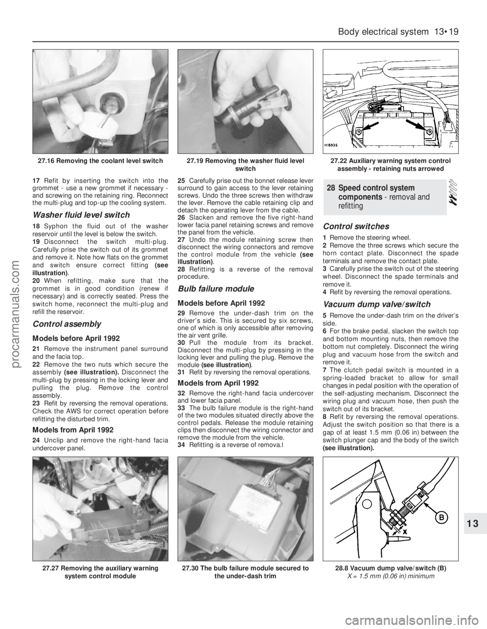
Carefully prise the switch out of its grommet
and remove it. Note how flats on the grommet
and switch ensure correct fitting (see
illustration).
20When refitting, make sure that the
grommet is in good condition (renew if
necessary) and is correctly seated. Press the
switch home, reconnect the multi-plug and
refill the reservoir.
Control assembly
Models before April 1992
21Remove the instrument panel surround
and the facia top.
22Remove the two nuts which secure the
assembly(see illustration).Disconnect the
multi-plug by pressing in the locking lever and
pulling the plug. Remove the control
assembly.
23Refit by reversing the removal operations.
Check the AWS for correct operation before
refitting the disturbed trim.
Models from April 1992
24Unclip and remove the right-hand facia
undercover panel.25Carefully prise out the bonnet release lever
surround to gain access to the lever retaining
screws. Undo the three screws then withdraw
the lever. Remove the cable retaining clip and
detach the operating lever from the cable.
26Slacken and remove the five right-hand
lower facia panel retaining screws and remove
the panel from the vehicle.
27Undo the module retaining screw then
disconnect the wiring connectors and remove
the control module from the vehicle (see
illustration).
28Refitting is a reverse of the removal
procedure.
Bulb failure module
Models before April 1992
29Remove the under-dash trim on the
driver’s side. This is secured by six screws,
one of which is only accessible after removing
the air vent grille.
30Pull the module from its bracket.
Disconnect the multi-plug by pressing in the
locking lever and pulling the plug. Remove the
module (see illustration).
31Refit by reversing the removal operations.
Models from April 1992
32Remove the right-hand facia undercover
and lower facia panel.
33The bulb failure module is the right-hand
of the two modules situated directly above the
control pedals. Release the module retaining
clips then disconnect the wiring connector and
remove the module from the vehicle.
34Refitting is a reverse of remova.l
Control switches
1Remove the steering wheel.
2Remove the three screws which secure the
horn contact plate. Disconnect the spade
terminals and remove the contact plate.
3Carefully prise the switch out of the steering
wheel. Disconnect the spade terminals and
remove it.
4Refit by reversing the removal operations.
Vacuum dump valve/switch
5Remove the under-dash trim on the driver’s
side.
6For the brake pedal, slacken the switch top
and bottom mounting nuts, then remove the
bottom nut completely. Disconnect the wiring
plug and vacuum hose from the switch and
remove it.
7The clutch pedal switch is mounted in a
spring-loaded bracket to allow for small
changes in pedal position with the operation of
the self-adjusting mechanism. Disconnect the
wiring plug and vacuum hose, then push the
switch out of its bracket.
8Refit by reversing the removal operations.
Adjust the switch position so that there is a
gap of at least 1.5 mm (0.06 in) between the
switch plunger cap and the body of the switch
(see illustration).
28Speed control system
components - removal and
refitting
Body electrical system 13•19
13
27.16 Removing the coolant level switch27.19 Removing the washer fluid level
switch27.22 Auxiliary warning system control
assembly - retaining nuts arrowed
27.27 Removing the auxiliary warning
system control module27.30 The bulb failure module secured to
the under-dash trim28.8 Vacuum dump valve/switch (B)
X = 1.5 mm (0.06 in) minimum
procarmanuals.com
Page 239 of 255
REF•4
Whenever servicing, repair or overhaul work
is carried out on the car or its components, it is
necessary to observe the following procedures
and instructions. This will assist in carrying out
the operation efficiently and to a professional
standard of workmanship.
Joint mating faces and gaskets
When separating components at their
mating faces, never insert screwdrivers or
similar implements into the joint between the
faces in order to prise them apart. This can
cause severe damage which results in oil
leaks, coolant leaks, etc upon reassembly.
Separation is usually achieved by tapping
along the joint with a soft-faced hammer in
order to break the seal. However, note that this
method may not be suitable where dowels are
used for component location.
Where a gasket is used between the mating
faces of two components, ensure that it is
renewed on reassembly, and fit it dry unless
otherwise stated in the repair procedure. Make
sure that the mating faces are clean and dry,
with all traces of old gasket removed. When
cleaning a joint face, use a tool which is not
likely to score or damage the face, and remove
any burrs or nicks with an oilstone or fine file.
Make sure that tapped holes are cleaned
with a pipe cleaner, and keep them free of
jointing compound, if this is being used, unless
specifically instructed otherwise.
Ensure that all orifices, channels or pipes
are clear, and blow through them, preferably
using compressed air.
Oil seals
Oil seals can be removed by levering them
out with a wide flat-bladed screwdriver or
similar implement. Alternatively, a number of
self-tapping screws may be screwed into the
seal, and these used as a purchase for pliers
or some similar device in order to pull the seal
free.
Whenever an oil seal is removed from its
working location, either individually or as part
of an assembly, it should be renewed.
The very fine sealing lip of the seal is easily
damaged, and will not seal if the surface it
contacts is not completely clean and free from
scratches, nicks or grooves.
Protect the lips of the seal from any surface
which may damage them in the course of
fitting. Use tape or a conical sleeve where
possible. Lubricate the seal lips with oil before
fitting and, on dual-lipped seals, fill the space
between the lips with grease.
Unless otherwise stated, oil seals must be
fitted with their sealing lips toward the
lubricant to be sealed.
Use a tubular drift or block of wood of the
appropriate size to install the seal and, if the
seal housing is shouldered, drive the seal
down to the shoulder. If the seal housing is
unshouldered, the seal should be fitted with its
face flush with the housing top face (unless
otherwise instructed).
Screw threads and fastenings
Seized nuts, bolts and screws are quite a
common occurrence where corrosion has set
in, and the use of penetrating oil or releasing
fluid will often overcome this problem if the
offending item is soaked for a while before
attempting to release it. The use of an impact
driver may also provide a means of releasing
such stubborn fastening devices, when used
in conjunction with the appropriate
screwdriver bit or socket. If none of these
methods works, it may be necessary to resort
to the careful application of heat, or the use of
a hacksaw or nut splitter device.
Studs are usually removed by locking two
nuts together on the threaded part, and then
using a spanner on the lower nut to unscrew
the stud. Studs or bolts which have broken off
below the surface of the component in which
they are mounted can sometimes be removed
using a proprietary stud extractor. Always
ensure that a blind tapped hole is completely
free from oil, grease, water or other fluid
before installing the bolt or stud. Failure to do
this could cause the housing to crack due to
the hydraulic action of the bolt or stud as it is
screwed in.
When tightening a castellated nut to accept
a split pin, tighten the nut to the specified
torque, where applicable, and then tighten
further to the next split pin hole. Never slacken
the nut to align the split pin hole, unless stated
in the repair procedure.
When checking or retightening a nut or bolt
to a specified torque setting, slacken the nut
or bolt by a quarter of a turn, and then
retighten to the specified setting. However,
this should not be attempted where angular
tightening has been used.
For some screw fastenings, notably cylinder
head bolts or nuts, torque wrench settings are
no longer specified for the latter stages of
tightening, “angle-tightening” being called up
instead. Typically, a fairly low torque wrench
setting will be applied to the bolts/nuts in
the correct sequence, followed by one or
more stages of tightening through specified
angles.
Locknuts, locktabs and washers
Any fastening which will rotate against a
component or housing in the course of
tightening should always have a washer
between it and the relevant component or
housing.
Spring or split washers should always be
renewed when they are used to lock a critical
component such as a big-end bearing
retaining bolt or nut. Locktabs which are
folded over to retain a nut or bolt should
always be renewed.
Self-locking nuts can be re-used in non-
critical areas, providing resistance can be felt
when the locking portion passes over the bolt
or stud thread. However, it should be noted
that self-locking stiffnuts tend to lose theireffectiveness after long periods of use, and in
such cases should be renewed as a matter of
course.
Split pins must always be replaced with new
ones of the correct size for the hole.
When thread-locking compound is found on
the threads of a fastener which is to be re-
used, it should be cleaned off with a wire
brush and solvent, and fresh compound
applied on reassembly.
Special tools
Some repair procedures in this manual
entail the use of special tools such as a press,
two or three-legged pullers, spring
compressors, etc. Wherever possible, suitable
readily-available alternatives to the
manufacturer’s special tools are described,
and are shown in use. Unless you are highly-
skilled and have a thorough understanding of
the procedures described, never attempt to
bypass the use of any special tool when the
procedure described specifies its use. Not
only is there a very great risk of personal injury,
but expensive damage could be caused to the
components involved.
Environmental considerations
When disposing of used engine oil, brake
fluid, antifreeze, etc, give due consideration to
any detrimental environmental effects. Do not,
for instance, pour any of the above liquids
down drains into the general sewage system,
or onto the ground to soak away. Many local
council refuse tips provide a facility for waste
oil disposal, as do some garages. If none of
these facilities are available, consult your local
Environmental Health Department for further
advice.
With the universal tightening-up of
legislation regarding the emission of
environmentally-harmful substances from
motor vehicles, most current vehicles have
tamperproof devices fitted to the main
adjustment points of the fuel system. These
devices are primarily designed to prevent
unqualified persons from adjusting the fuel/air
mixture, with the chance of a consequent
increase in toxic emissions. If such devices are
encountered during servicing or overhaul, they
should, wherever possible, be renewed or
refitted in accordance with the vehicle
manufacturer’s requirements or current
legislation.
Note: It is
antisocial and
illegal to dump
oil down the
drain. To find
the location of
your local oil
recycling
bank, call this
number free.
General Repair Procedures
procarmanuals.com