1985 FORD GRANADA four wheel drive
[x] Cancel search: four wheel drivePage 59 of 255
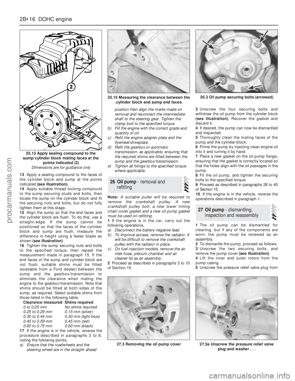
13Apply a sealing compound to the faces of
the cylinder block and sump at the points
indicated(see illustration).
14Apply suitable thread-locking compound
to the sump securing studs and bolts, then
locate the sump on the cylinder block and fit
the securing nuts and bolts, but do not fully
tighten them at this stage.
15Align the sump so that the end faces and
the cylinder block are flush. To do this, use a
straight-edge. If the sump cannot be
positioned so that the faces of the cylinder
block and sump are flush, measure the
difference in height using a feeler blade as
shown (see illustration).
16Tighten the sump securing nuts and bolts
to the specified torque, then repeat the
measurement made in paragraph 15. If the
end faces of the sump and cylinder block are
not flush, suitable shims must be fitted
(available from a Ford dealer) between the
sump and the gearbox/transmission to
eliminate the clearance when mating the
engine to the gearbox/transmission. Note that
shims should be fitted at both sides of the
sump, as required. Select suitable shims from
those listed in the following table.
Clearance measuredShims required
0 to 0.25 mmNo shims required
0.25 to 0.29 mm0.15 mm (silver)
0.30 to 0.44 mm0.30 mm (light blue)
0.45 to 0.59 mm0.45 mm (red)
0.60 to 0.75 mm0.60 mm (black)
17If the engine is in the vehicle, reverse the
procedure described in paragraphs 3 to 8,
noting the following points.
a)Ensure that the roadwheels and the
steering wheel are in the straight-aheadposition then align the marks made on
removal and reconnect the intermediate
shaft to the steering gear. Tighten the
clamp bolt to the specified torque.
b)Fill the engine with the correct grade and
quantity of oil.
c)Refit the engine adapter plate and the
flywheel/driveplate.
d)Refit the gearbox or automatic
transmission, as applicable, ensuring that
the required shims are fitted between the
sump and the gearbox/transmission.
e)Tighten all fixings to the specified torque
where applicable.
Note: A suitable puller will be required to
remove the crankshaft pulley. A new
crankshaft pulley bolt, a new lower timing
chain cover gasket and a new oil pump gasket
must be used on refitting.
1If the engine is in the car, carry out the
following operations.
a)Disconnect the battery negative lead.
b)To Improve access, remove the radiator. It
will be difficult to remove the crankshaft
pulley with the radiator in place.
c)On fuel-injection models, remove the air
inlet hose, plenum chamber and air
cleaner lid as an assembly.
2Proceed as described in paragraphs 3 to 10
of Section 15.3Unscrew the four securing bolts and
withdraw the oil pump from the cylinder block
(see illustration). Recover the gasket and
discard it.
4If desired, the pump can now be dismantled
and inspected.
5Thoroughly clean the mating faces of the
pump and the cylinder block.
6Prime the pump by injecting clean engine oil
into it and turning it by hand.
7Place a new gasket on the oil pump flange,
ensuring that the gasket is correctly located so
that the holes align with the oil passages in the
pump.
8Fit the oil pump, and tighten the securing
bolts to the specified torque.
9Proceed as described in paragraphs 28 to 40
of Section 15.
10If the engine is in the vehicle, reverse the
operations described in paragraph 1.
1The oil pump can be dismantled for
cleaning, but if any of the components are
worn, the pump must be renewed as an
assembly.
2To dismantle the pump, proceed as follows.
3Unscrew the two securing bolts, and
remove the pump cover (see illustration).
4Lift the inner and outer rotors from the
pump casing.
5Unscrew the pressure relief valve plug from
27Oil pump - dismantling,
inspection and reassembly
26Oil pump - removal and
refitting
2B•16DOHCengine
25.13 Apply sealing compound to the
sump/cylinder block mating faces at the
points indicated (2)
Dimensions are for guidance only
27.3 Removing the oil pump cover27.5a Unscrew the pressure relief valve
plug and washer . . .
25.15 Measuring the clearance between the
cylinder block and sump end faces26.3 Oil pump securing bolts (arrowed)
procarmanuals.com
Page 60 of 255
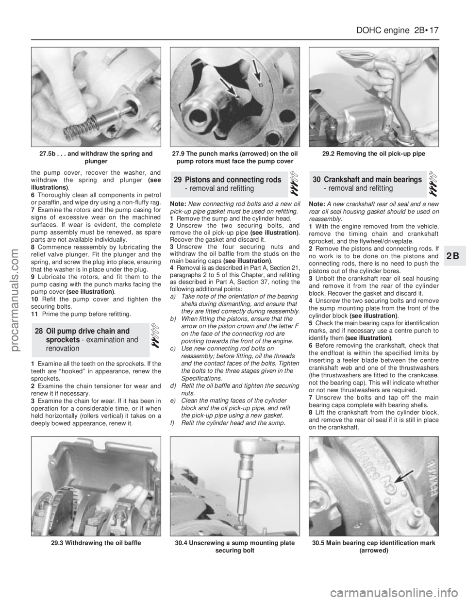
the pump cover, recover the washer, and
withdraw the spring and plunger (see
illustrations).
6Thoroughly clean all components in petrol
or paraffin, and wipe dry using a non-fluffy rag.
7Examine the rotors and the pump casing for
signs of excessive wear on the machined
surfaces. If wear is evident, the complete
pump assembly must be renewed, as spare
parts are not available individually.
8Commence reassembly by lubricating the
relief valve plunger. Fit the plunger and the
spring, and screw the plug into place, ensuring
that the washer is in place under the plug.
9Lubricate the rotors, and fit them to the
pump casing with the punch marks facing the
pump cover (see illustration).
10Refit the pump cover and tighten the
securing bolts.
11Prime the pump before refitting.
1Examine all the teeth on the sprockets. If the
teeth are “hooked” in appearance, renew the
sprockets.
2Examine the chain tensioner for wear and
renew it if necessary.
3Examine the chain for wear. If it has been in
operation for a considerable time, or if when
held horizontally (rollers vertical) it takes on a
deeply bowed appearance, renew it.Note: New connecting rod bolts and a new oil
pick-up pipe gasket must be used on refitting.
1Remove the sump and the cylinder head.
2Unscrew the two securing bolts, and
remove the oil pick-up pipe (see illustration).
Recover the gasket and discard it.
3Unscrew the four securing nuts and
withdraw the oil baffle from the studs on the
main bearing caps (see illustration).
4Removal is as described in Part A, Section 21,
paragraphs 2 to 5 of this Chapter, and refitting
as described in Part A, Section 37, noting the
following additional points:
a)Take note of the orientation of the bearing
shells during dismantling, and ensure that
they are fitted correctly during reassembly.
b)When fitting the pistons, ensure that the
arrow on the piston crown and the letter F
on the face of the connecting rod are
pointing towards the front of the engine.
c)Use new connecting rod bolts on
reassembly; before fitting, oil the threads
and the contact faces of the bolts. Tighten
the bolts to the three stages given in the
Specifications.
d)Refit the oil baffle and tighten the securing
nuts.
e)Clean the mating faces of the cylinder
block and the oil pick-up pipe, and refit
the pick-up pipe using a new gasket.
f)Refit the cylinder head and the sump.Note: A new crankshaft rear oil seal and a new
rear oil seal housing gasket should be used on
reassembly.
1With the engine removed from the vehicle,
remove the timing chain and crankshaft
sprocket, and the flywheel/driveplate.
2Remove the pistons and connecting rods. If
no work is to be done on the pistons and
connecting rods, there is no need to push the
pistons out of the cylinder bores.
3Unbolt the crankshaft rear oil seal housing
and remove it from the rear of the cylinder
block. Recover the gasket and discard it.
4Unscrew the two securing bolts and remove
the sump mounting plate from the front of the
cylinder block (see illustration).
5Check the main bearing caps for identification
marks, and if necessary use a centre punch to
identify them (see illustration).
6Before removing the crankshaft, check that
the endfloat is within the specified limits by
inserting a feeler blade between the centre
crankshaft web and one of the thrustwashers
(the thrustwashers are fitted to the crankcase,
not the bearing cap). This will indicate whether
or not new thrustwashers are required.
7Unscrew the bolts and tap off the main
bearing caps complete with bearing shells.
8Lift the crankshaft from the cylinder block,
and remove the rear oil seal if it is still in place
on the crankshaft.30Crankshaft and main bearings
- removal and refitting29Pistons and connecting rods
- removal and refitting
28Oil pump drive chain and
sprockets - examination and
renovation
DOHCengine 2B•17
2B
27.5b . . . and withdraw the spring and
plunger27.9 The punch marks (arrowed) on the oil
pump rotors must face the pump cover29.2 Removing the oil pick-up pipe
29.3 Withdrawing the oil baffle30.4 Unscrewing a sump mounting plate
securing bolt30.5 Main bearing cap identification mark
(arrowed)
procarmanuals.com
Page 67 of 255
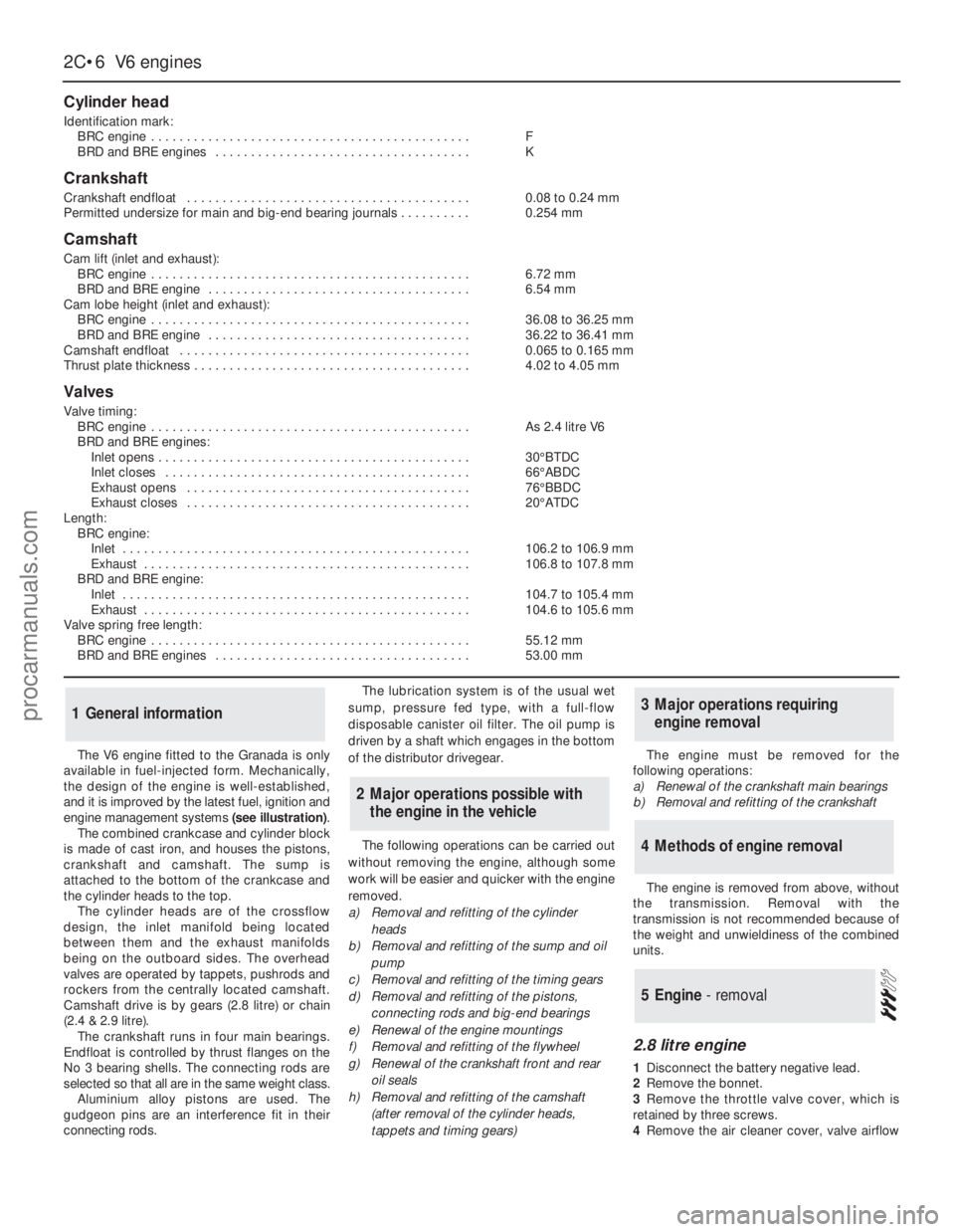
The V6 engine fitted to the Granada is only
available in fuel-injected form. Mechanically,
the design of the engine is well-established,
and it is improved by the latest fuel, ignition and
engine management systems (see illustration).
The combined crankcase and cylinder block
is made of cast iron, and houses the pistons,
crankshaft and camshaft. The sump is
attached to the bottom of the crankcase and
the cylinder heads to the top.
The cylinder heads are of the crossflow
design, the inlet manifold being located
between them and the exhaust manifolds
being on the outboard sides. The overhead
valves are operated by tappets, pushrods and
rockers from the centrally located camshaft.
Camshaft drive is by gears (2.8 litre) or chain
(2.4 & 2.9 litre).
The crankshaft runs in four main bearings.
Endfloat is controlled by thrust flanges on the
No 3 bearing shells. The connecting rods are
selected so that all are in the same weight class.
Aluminium alloy pistons are used. The
gudgeon pins are an interference fit in their
connecting rods.The lubrication system is of the usual wet
sump, pressure fed type, with a full-flow
disposable canister oil filter. The oil pump is
driven by a shaft which engages in the bottom
of the distributor drivegear.
The following operations can be carried out
without removing the engine, although some
work will be easier and quicker with the engine
removed.
a)Removal and refitting of the cylinder
heads
b)Removal and refitting of the sump and oil
pump
c)Removal and refitting of the timing gears
d)Removal and refitting of the pistons,
connecting rods and big-end bearings
e)Renewal of the engine mountings
f)Removal and refitting of the flywheel
g)Renewal of the crankshaft front and rear
oil seals
h)Removal and refitting of the camshaft
(after removal of the cylinder heads,
tappets and timing gears)The engine must be removed for the
following operations:
a)Renewal of the crankshaft main bearings
b)Removal and refitting of the crankshaft
The engine is removed from above, without
the transmission. Removal with the
transmission is not recommended because of
the weight and unwieldiness of the combined
units.
2.8 litre engine
1Disconnect the battery negative lead.
2Remove the bonnet.
3Remove the throttle valve cover, which is
retained by three screws.
4Remove the air cleaner cover, valve airflow
5Engine - removal
4Methods of engine removal
3Major operations requiring
engine removal
2Major operations possible with
the engine in the vehicle
1General information
2C•6V6 engines
Cylinder head
Identification mark:
BRC engine . . . . . . . . . . . . . . . . . . . . . . . . . . . . . . . . . . . . . . . . . . . . .F
BRD and BRE engines . . . . . . . . . . . . . . . . . . . . . . . . . . . . . . . . . . . .K
Crankshaft
Crankshaft endfloat . . . . . . . . . . . . . . . . . . . . . . . . . . . . . . . . . . . . . . . .0.08 to 0.24 mm
Permitted undersize for main and big-end bearing journals . . . . . . . . . .0.254 mm
Camshaft
Cam lift (inlet and exhaust):
BRC engine . . . . . . . . . . . . . . . . . . . . . . . . . . . . . . . . . . . . . . . . . . . . .6.72mm
BRD and BRE engine . . . . . . . . . . . . . . . . . . . . . . . . . . . . . . . . . . . . .6.54 mm
Cam lobe height (inlet and exhaust):
BRC engine . . . . . . . . . . . . . . . . . . . . . . . . . . . . . . . . . . . . . . . . . . . . .36.08 to 36.25 mm
BRD and BRE engine . . . . . . . . . . . . . . . . . . . . . . . . . . . . . . . . . . . . .36.22 to 36.41 mm
Camshaft endfloat . . . . . . . . . . . . . . . . . . . . . . . . . . . . . . . . . . . . . . . . .0.065 to 0.165 mm
Thrust plate thickness . . . . . . . . . . . . . . . . . . . . . . . . . . . . . . . . . . . . . . .4.02 to 4.05 mm
Valves
Valve timing:
BRC engine . . . . . . . . . . . . . . . . . . . . . . . . . . . . . . . . . . . . . . . . . . . . .As 2.4 litre V6
BRD and BRE engines:
Inlet opens . . . . . . . . . . . . . . . . . . . . . . . . . . . . . . . . . . . . . . . . . . . .30°BTDC
Inlet closes . . . . . . . . . . . . . . . . . . . . . . . . . . . . . . . . . . . . . . . . . . .66°ABDC
Exhaust opens . . . . . . . . . . . . . . . . . . . . . . . . . . . . . . . . . . . . . . . .76°BBDC
Exhaust closes . . . . . . . . . . . . . . . . . . . . . . . . . . . . . . . . . . . . . . . .20°ATDC
Length:
BRC engine:
Inlet . . . . . . . . . . . . . . . . . . . . . . . . . . . . . . . . . . . . . . . . . . . . . . . . .106.2 to 106.9 mm
Exhaust . . . . . . . . . . . . . . . . . . . . . . . . . . . . . . . . . . . . . . . . . . . . . .106.8 to 107.8 mm
BRD and BRE engine:
Inlet . . . . . . . . . . . . . . . . . . . . . . . . . . . . . . . . . . . . . . . . . . . . . . . . .104.7 to 105.4 mm
Exhaust . . . . . . . . . . . . . . . . . . . . . . . . . . . . . . . . . . . . . . . . . . . . . .104.6 to 105.6 mm
Valve spring free length:
BRC engine . . . . . . . . . . . . . . . . . . . . . . . . . . . . . . . . . . . . . . . . . . . . .55.12 mm
BRD and BRE engines . . . . . . . . . . . . . . . . . . . . . . . . . . . . . . . . . . . .53.00 mm
procarmanuals.com
Page 131 of 255
Models covered in this Manual have disc
brakes fitted all round. The footbrake operates
hydraulically on all four wheels, and the
handbrake operates mechanically on the rear
wheels. Both footbrake and handbrake are
self-adjusting in use.
Ford’s anti-lock braking system (ABS) is
fitted to all models. The system monitors the
rotational speed of each roadwheel. When a
wheel begins to lock under heavy braking, the
ABS reduces the hydraulic pressure to that
wheel, so preventing it from locking. When this
happens a pulsating effect will be noticed at
the brake pedal. On some road surfaces the
tyres may squeal when braking hard even
though the wheels are not locked.
The main components of the system are the
hydraulic unit, the calipers, pads and discs,
the wheel sensors and the “brain” or control
module. The hydraulic unit contains the
elements of a traditional master cylinder, plus
an electric motor and pump, a pressure
accumulator and control valves. The pump is
the source of pressure for the system and
does away with the need for a vacuum servo.
The hydraulic circuit is split front and rear,
as is normal practice with rear-wheel drive
vehicles. In the event that the hydraulic pump
fails, unassisted braking effort is still available
on the front calipers only.
Warning lights inform the driver of low brake
fluid level, ABS failure and (on some models)
brake pad wear. The low fluid level light
doubles as a “handbrake on” light; if it
illuminates at the same time as the ABS
warning light, it warns of low hydraulic
pressure.
ABS cannot overturn the laws of physics:
stopping distances will inevitably be greater on
loose or slippery surfaces. However, the system
should allow even inexperienced drivers to
retain directional control under panic braking.
From August 1986 the following
modifications were made to the braking
system.
a)The relays differ from earlier versions.b)The hydraulic pump is constructed of iron
rather than alloy.
c)A new pressure warning switch is used.
d)The earlier high pressure rubber hose is
replaced by a steel pipe.
To overcome the problem of excessive rear
brake pad wear, Ford introduced a differential
valve which is screwed into the ABS valve
block.The valve limits the pressure applied to
the rear brake calipers and so reduces brake
pad wear. From 1988 onwards, the valve has
been fitted during production. The differential
valve can also be fitted to earlier models. Refer
to your Ford dealer for further information.
From April 1992 onwards, the models
covered in this Manual were equipped with a
new Teves MK IV anti-lock braking system
instead of the Teves MK II system fitted to the
earlier models.
The Teves MK IV system differs from the
earlier MK II system in the following ways.
a)The source of hydraulic pressure for the
system is a conventional master cylinder
and vacuum servo assembly.
b)A valve block and pump assembly is used
instead of the hydraulic control unit. The
block contains the inlet and outlet
solenoid valves that control the hydraulic
system. There are three pairs of valves,
one for each brake circuit (paragraph c).
c)The hydraulic braking system consists of
three separate circuits; one for each front
brake (which are totally independent of
each other), and a joint circuit which
operates both rear brakes.
d)A G (gravity) switch is incorporated in the
system. This is an inertia type switch and
informs the control module when the
vehicle is decelerating rapidly.
e)A Pedal Travel Sensor (PTS) is fitted to the
vacuum servo unit. The PTS informs the
control module of the position of the brake
pedal when the anti-lock sequence starts
and ensures that a constant pedal height
is maintained during the sequence.
The MK IV system operates as follows.
During normal operation the system
functions in the same way as a non-ABS
system would. During this time the three inlet
valves in the valve block are open and theoutlet valves are closed, allowing full hydraulic
pressure present in the master cylinder to act
on the main braking circuit. If the control
module receives a signal from one of the
wheel sensors and senses that a wheel is
about to lock, it closes the relevant inlet valve
in the valve block which then isolates the
brake caliper on the wheel which is about to
lock from the master cylinder, effectively
sealing in the hydraulic pressure. If the speed
of rotation of the wheel continues to decrease
at an abnormal rate, the control module will
then open the relevant outlet valve in the valve
block; this allows the fluid from the relevant
hydraulic circuit to return to the master
cylinder reservoir, releasing pressure on the
brake caliper so that the brake is released. The
pump in the valve block also operates to assist
in the quick release of pressure. Once the
speed of rotation of the wheel returns to an
acceptable rate the pump stops, the outlet
valve closes and the inlet valve is opened,
allowing the hydraulic master cylinder
pressure to return to the caliper which then
reapplies the brake. This cycle can be carried
many times a second. The solenoid valves
connected to the front calipers operate
independently, but the valve connected to the
rear calipers operates both calipers
simultaneously.
The operation of the ABS system is entirely
dependent on electrical signals. To prevent
the system responding to any inaccurate
signals, a built-in safety circuit monitors all
signals received by the control module. If an
inaccurate signal or low battery voltage is
detected, the ABS system is automatically
shut down and the warning lamp on the
instrument cluster is illuminated to inform the
driver that the ABS system is not operational.
Whilst in this state the system functions in the
same way as a non-ABS system would. If a
fault does develop in the ABS system, the car
must be taken to a Ford dealer for fault
diagnosis and repair. The system is equipped
with a diagnostic plug into which a special
diagnostic (STAR) tester can be plugged. This
allows faults to be easily traced.
1General information
10•2Braking system
Torque wrench settingsNmlbf ft
Front caliper:
To stub axle carrier . . . . . . . . . . . . . . . . . . . . . . . . . . . . . . . . . . . . . . .51 to 6138 to 45
Slide bolts . . . . . . . . . . . . . . . . . . . . . . . . . . . . . . . . . . . . . . . . . . . . . .20 to 2515 to 18
Rear caliper:
Bracket to carrier plate . . . . . . . . . . . . . . . . . . . . . . . . . . . . . . . . . . . .51 to 6138 to 45
Slide bolts . . . . . . . . . . . . . . . . . . . . . . . . . . . . . . . . . . . . . . . . . . . . . .31 to 3523 to 26
Hydraulic unit to bulkhead . . . . . . . . . . . . . . . . . . . . . . . . . . . . . . . . . . .41 to 5130 to 38
Accumulator to pump body . . . . . . . . . . . . . . . . . . . . . . . . . . . . . . . . . .35 to 4526 to 33
Pump mounting bolts . . . . . . . . . . . . . . . . . . . . . . . . . . . . . . . . . . . . . . .7 to 95 to 7
High pressure hose banjo bolts . . . . . . . . . . . . . . . . . . . . . . . . . . . . . . .16 to 2412 to 18
Reservoir mounting bolts . . . . . . . . . . . . . . . . . . . . . . . . . . . . . . . . . . . .4 to 63 to 4
Wheel sensor fixing bolts . . . . . . . . . . . . . . . . . . . . . . . . . . . . . . . . . . . .8 to 116 to 8
Vacuum servo unit retaining nuts (Teves MK IV) . . . . . . . . . . . . . . . . . .35 to 4526 to 33
Master cylinder retaining nuts (Teves MK IV) . . . . . . . . . . . . . . . . . . . . .20 to 2515 to 18
Valve block and pump assembly mounting nuts (Teves MK IV) . . . . . . .21 to 2815 to 21
procarmanuals.com
Page 154 of 255
15Bleed the brake hydraulic system and
adjust the handbrake on completion.
Models from 1987
16From 1987, the tab washer which secures
the guide plate centre bolt on each side has
been deleted. A self-locking bolt and plain
washer are used instead.
17The new bolt and washer should be fitted
to earlier models if the old bolt has been
removed for any reason. The tab washer
should be discarded.
18The tightening torque for the new bolt
remains the same as that given for the original.
1Remove the wheel trim. Apply the
handbrake and chock the front wheels.
2Slacken the driveshaft stub axle. This nut is
very tight. The left-hand nut has aleft-hand
thread, therefore it is undone clockwise.
3Remove the brake disc.
4Remove the driveshaft stub axle.
5Remove the four bolts which secure the
hub. Pull the hub off the driveshaft stub,
leaving the disc splash shield loose.
6Refit by reversing the removal operations.
Carry out the final tightening of the driveshaft
stub nut with the wheels on the ground.
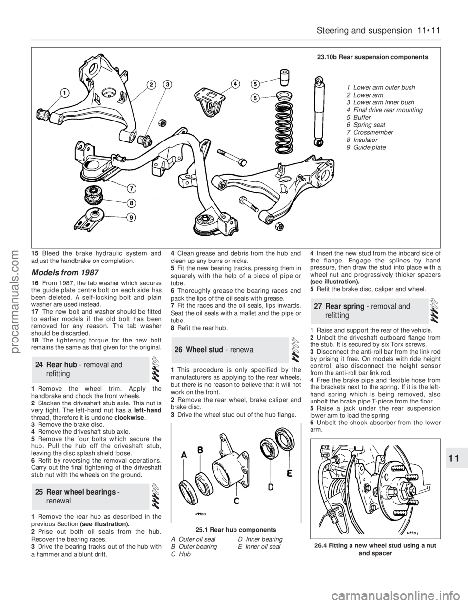
1Remove the rear hub as described in the
previous Section (see illustration).
2Prise out both oil seals from the hub.
Recover the bearing races.
3Drive the bearing tracks out of the hub with
a hammer and a blunt drift.4Clean grease and debris from the hub and
clean up any burrs or nicks.
5Fit the new bearing tracks, pressing them in
squarely with the help of a piece of pipe or
tube.
6Thoroughly grease the bearing races and
pack the lips of the oil seals with grease.
7Fit the races and the oil seals, lips inwards.
Seat the oil seals with a mallet and the pipe or
tube.
8Refit the rear hub.
1This procedure is only specified by the
manufacturers as applying to the rear wheels,
but there is no reason to believe that it will not
work on the front.
2Remove the rear wheel, brake caliper and
brake disc.
3Drive the wheel stud out of the hub flange. 4Insert the new stud from the inboard side of
the flange. Engage the splines by hand
pressure, then draw the stud into place with a
wheel nut and progressively thicker spacers
(see illustration).
5Refit the brake disc, caliper and wheel.
1Raise and support the rear of the vehicle.
2Unbolt the driveshaft outboard flange from
the stub. It is secured by six Torx screws.
3Disconnect the anti-roll bar from the link rod
by prising it free. On models with ride height
control, also disconnect the height sensor
from the anti-roll bar link rod.
4Free the brake pipe and flexible hose from
the brackets next to the spring. If it is the left-
hand spring which is being removed, also
unbolt the brake pipe T-piece from the floor.
5Raise a jack under the rear suspension
lower arm to load the spring.
6Unbolt the shock absorber from the lower
arm.
27Rear spring - removal and
refitting
26Wheel stud - renewal
25Rear wheel bearings -
renewal
24Rear hub - removal and
refitting
Steering and suspension 11•11
11
25.1 Rear hub components
A Outer oil seal
B Outer bearing
C HubD Inner bearing
E Inner oil seal26.4 Fitting a new wheel stud using a nut
and spacer
23.10b Rear suspension components
1 Lower arm outer bush
2 Lower arm
3 Lower arm inner bush
4 Final drive rear mounting
5 Buffer
6 Spring seat
7 Crossmember
8 Insulator
9 Guide plate
procarmanuals.com
Page 188 of 255
1Disconnect the battery negative lead.
2Remove the steering column upper and
lower shrouds.
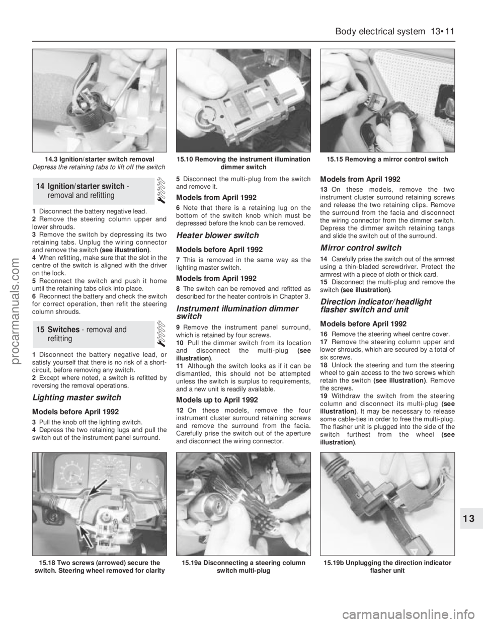
3Remove the switch by depressing its two
retaining tabs. Unplug the wiring connector
and remove the switch (see illustration).
4When refitting, make sure that the slot in the
centre of the switch is aligned with the driver
on the lock.
5Reconnect the switch and push it home
until the retaining tabs click into place.
6Reconnect the battery and check the switch
for correct operation, then refit the steering
column shrouds.
1Disconnect the battery negative lead, or
satisfy yourself that there is no risk of a short-
circuit, before removing any switch.
2Except where noted, a switch is refitted by
reversing the removal operations.
Lighting master switch
Models before April 1992
3Pull the knob off the lighting switch.
4Depress the two retaining lugs and pull the
switch out of the instrument panel surround. 5Disconnect the multi-plug from the switch
and remove it.
Models from April 1992
6Note that there is a retaining lug on the
bottom of the switch knob which must be
depressed before the knob can be removed.
Heater blower switch
Models before April 1992
7This is removed in the same way as the
lighting master switch.
Models from April 1992
8The switch can be removed and refitted as
described for the heater controls in Chapter 3.
Instrument illumination dimmer
switch
9Remove the instrument panel surround,
which is retained by four screws.
10Pull the dimmer switch from its location
and disconnect the multi-plug (see
illustration).
11Although the switch looks as if it can be
dismantled, this should not be attempted
unless the switch is surplus to requirements,
and a new unit is readily available.
Models up to April 1992
12On these models, remove the four
instrument cluster surround retaining screws
and remove the surround from the facia.
Carefully prise the switch out of the aperture
and disconnect the wiring connector.
Models from April 1992
13On these models, remove the two
instrument cluster surround retaining screws
and release the two retaining clips. Remove
the surround from the facia and disconnect
the wiring connector from the dimmer switch.
Depress the dimmer switch retaining tangs
and slide the switch out of the surround.
Mirror control switch
14Carefully prise the switch out of the armrest
using a thin-bladed screwdriver. Protect the
armrest with a piece of cloth or thick card.
15Disconnect the multi-plug and remove the
switch (see illustration).
Direction indicator/headlight
flasher switch and unit
Models before April 1992
16Remove the steering wheel centre cover.
17Remove the steering column upper and
lower shrouds, which are secured by a total of
six screws.
18Unlock the steering and turn the steering
wheel to gain access to the two screws which
retain the switch (see illustration). Remove
the screws.
19Withdraw the switch from the steering
column and disconnect its multi-plug (see
illustration). It may be necessary to release
some cable-ties in order to free the multi-plug.
The flasher unit is plugged into the side of the
switch furthest from the wheel (see
illustration).15Switches - removal and
refitting
14Ignition/starter switch -
removal and refitting
Body electrical system 13•11
13
14.3 Ignition/starter switch removal
Depress the retaining tabs to lift off the switch15.10 Removing the instrument illumination
dimmer switch15.15 Removing a mirror control switch
15.18 Two screws (arrowed) secure the
switch. Steering wheel removed for clarity15.19a Disconnecting a steering column
switch multi-plug15.19b Unplugging the direction indicator
flasher unit
procarmanuals.com