1985 FORD GRANADA air condition
[x] Cancel search: air conditionPage 13 of 255
1Work around the vehicle, and lubricate the
hinges and locks with a light machine oil.
2Lightly lubricate the bonnet release
mechanism and exposed sections of inner
cable with a smear of grease.
3Check the security and operation of all
hinges, latches and locks, adjusting them
where required. Where applicable, check the
operation of the central locking system.
4Check the condition and operation of the
tailgate struts, renewing them if either is
leaking or is no longer able to support the
tailgate securely when raised.
SOHC and V6 engines
1The correct functioning of the spark plugs is
vital for the correct running and efficiency of
the engine. It is essential that the plugs fitted
are appropriate for the engine.
2Make sure that the ignition is switched off
before inspecting the HT leads to see if they
carry their cylinder numbers - if not, number
each lead using sticky tape or paint.
3Pull the HT lead connectors off the plugs.
Pull on the connectors, not on the leads.
4Blow away any dirt from around the spark
plug recesses in the cylinder head(s).
5Unscrew and remove the plugs, using a
proprietary plug spanner or a spark plug
socket, extension and ratchet.
6The condition of the plugs will tell much
about the overall condition of the engine. If the
insulator nose of the spark plug is clean and
white, with no deposits, this is indicative of a
weak mixture or too hot a plug (a hot plug
transfers heat away from the electrode slowly,
a cold plug transfers heat away quickly).
7If the tip and insulator nose are covered with
hard black-looking deposits, then this is
indicative that the mixture is too rich. Should
the plug be black and oily, then it is likely that
the engine is fairly worn, as well as the mixture
being too rich.
8If the insulator nose is covered with light tan
to greyish-brown deposits, then the mixture is
correct, and it is likely that the engine is in
good condition.
9Apply a smear of anti-seize compound to
the threads of the new plugs. Make sure that
theinsulators are clean and that the screwed
HT lead adapters are tight. Pay particular
attention to the plug seating surfaces on OHC
engines, since these plugs have no sealing
washers (“taper seat” type) and any dirt will
cause a bad seal.
10Screw each plug into its hole by hand. If a
plug is reluctant to go in, do not force it with a
spanner, but unscrew it and try again. If the
plug is cross-threaded, it is the cylinder head
which will be damaged.11Final tightening of the spark plugs should
ideally be carried out using a torque wrench.
The tightening torques are given in the
Specifications. If a torque wrench is not
available, tighten the plugs beyond the point
where they contact the head as follows:
OHC (taper seat plugs) - One-sixteenth of a
turn maximum
V6 (plugs with washers) - One-quarter of a
turn maximum
12If the taper seat type of plug is
overtightened, the sealing faces will bite
together and removal will be very difficult.
13Refit the HT leads to the plugs, paying
attention to the cylinder numbers. Push each
connector firmly onto its plug.
14Run the engine to verify that the HT leads
have been refitted correctly.
DOHC engines
15Proceed as described above whilst noting
the following points.
a)Remove the air cleaner as described in
Chapter 4.
b)The minimal length of number 3 HT lead
makes removal from the spark plug
difficult. It is advisable to remove this lead
from the distributor prior to removing it
from the spark plug.
c)The spark plugs are deeply recessed in
the cylinder head and it will be necessary
to use a spark plug socket with a long
extension bar. If possible, use a spark plug
socket with a rubber grip inside as this will
hold onto the spark plug once loosened
and will enable the spark plugs to be
withdrawn and refitted more easily.
SOHC and all V6 engines
1All of these engines have one or two
drivebelts which drive the water pump and
alternator from the crankshaft pulley. When
power steering is fitted, the same belts drive
the steering pump. The air conditioning
compressor, when fitted, is driven
independently.
2Periodically inspect the drivebelt(s) for
fraying, cracks, glazing or other damage. Turn
the engine so that the full length of the belt(s)
can be viewed. Renew belts which are in poor
condition. When twin drivebelts are fitted, both
must be renewed together, even if only one is
damaged.
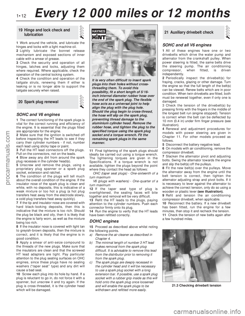
3Check the tension of the drivebelt(s) by
pressing firmly with the fingers in the middle of
the longest belt run (engine stopped). Tension
is correct when the belt can be deflected by
10 mm (0.4 in) under firm finger pressure (see
illustration).
4Renewal and adjustment procedures for
models with power steering are given in
Chapter 11. For other models proceed as
follows.
5Disconnect the battery negative lead.
6On models with air conditioning, remove the
compressor drivebelt.
7Slacken the alternator pivot and adjusting
bolts. Swing the alternator towards the engine
and slip the belt(s) off the pulleys.
8Fit the new belt(s) over the pulleys. Move
the alternator away from the engine until the
belt tension is correct, then tighten the
alternator adjusting strap and pivot bolts. If it
is necessary to lever against the alternator to
achieve the correct tension, only do so using a
wooden or plastic lever(seeillustration).
9Refit and tension the air conditioning
compressor drivebelt, when applicable.
10Reconnect the battery. If a new drivebelt
has been fitted, run the engine for a few
minutes, then stop it and recheck the tension.
11Check the tension of new belts again after
a few hundred miles.
21Auxiliary drivebelt check
20Spark plug renewal
19Hinge and lock check and
lubrication
1•12Every 12 000 miles or 12 months
21.3 Checking drivebelt tension
It is very often difficult to insert spark
plugs into their holes without cross-
threading them. To avoid this
possibility, fit a short length of 5/16-
inch internal diameter rubber hose over
the end of the spark plug. The flexible
hose acts as a universal joint to help
align the plug with the plug hole.
Should the plug begin to cross-thread,
the hose will slip on the spark plug,
preventing thread damage to the
aluminium cylinder head. Remove the
rubber hose, and tighten the plug to the
specified torque using the spark plug
socket and a torque wrench. Fit the
remaining spark plugs in the same
manner.
procarmanuals.com
Page 14 of 255
DOHC engines
12On this engine, the coolant/alternator
drivebelt also drives the power steering pump
and (where applicable) the air conditioning
compressor. The drivebelt tension is set by an
automatic tensioner assembly.
13The condition of the drivebelt should be
checked as described above.
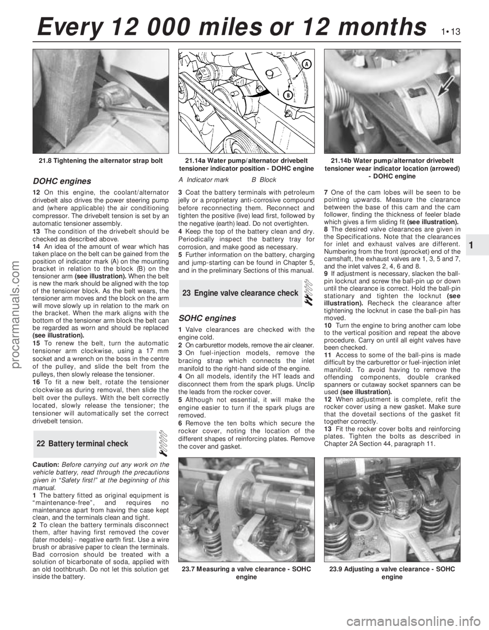
14An idea of the amount of wear which has
taken place on the belt can be gained from the
position of indicator mark (A) on the mounting
bracket in relation to the block (B) on the
tensioner arm (see illustration).When the belt
is new the mark should be aligned with the top
of the tensioner block. As the belt wears, the
tensioner arm moves and the block on the arm
will move slowly up in relation to the mark on
the bracket. When the mark aligns with the
bottom of the tensioner arm block the belt can
be regarded as worn and should be replaced
(see illustration).
15To renew the belt, turn the automatic
tensioner arm clockwise, using a 17 mm
socket and a wrench on the boss in the centre
of the pulley, and slide the belt from the
pulleys, then slowly release the tensioner.
16To fit a new belt, rotate the tensioner
clockwise as during removal, then slide the
belt over the pulleys. With the belt correctly
located, slowly release the tensioner; the
tensioner will automatically set the correct
drivebelt tension.
Caution:Before carrying out any work on the
vehicle battery, read through the precautions
given in “Safety first!” at the beginning of this
manual.
1The battery fitted as original equipment is
“maintenance-free”, and requires no
maintenance apart from having the case kept
clean, and the terminals clean and tight.
2To clean the battery terminals disconnect
them, after having first removed the cover
(later models) -negative earth first. Use a wire
brush or abrasive paper to clean the terminals.
Bad corrosion should be treated with a
solution of bicarbonate of soda, applied with
an old toothbrush. Do not let this solution get
inside the battery.3Coat the battery terminals with petroleum
jelly or a proprietary anti-corrosive compound
before reconnecting them. Reconnect and
tighten the positive (live) lead first, followed by
the negative (earth) lead. Do not overtighten.
4Keep the top of the battery clean and dry.
Periodically inspect the battery tray for
corrosion, and make good as necessary.
5Further information on the battery, charging
and jump-starting can be found in Chapter 5,
and in the preliminary Sections of this manual.
SOHC engines
1Valve clearances are checked with the
engine cold.
2On carburettor models, remove the air cleaner.
3On fuel-injection models, remove the
bracing strap which connects the inlet
manifold to the right-hand side of the engine.
4On all models, identify the HT leads and
disconnect them from the spark plugs. Unclip
the leads from the rocker cover.
5Although not essential, it will make the
engine easier to turn if the spark plugs are
removed.
6Remove the ten bolts which secure the
rocker cover, noting the location of the
different shapes of reinforcing plates. Remove
the cover and gasket.7One of the cam lobes will be seen to be
pointing upwards. Measure the clearance
between the base of this cam and the cam
follower, finding the thickness of feeler blade
which gives a firm sliding fit(see illustration).
8The desired valve clearances are given in
the Specifications. Note that the clearances
for inlet and exhaust valves are different.
Numbering from the front (sprocket) end of the
camshaft, the exhaust valves are 1, 3, 5 and 7,
and the inlet valves 2, 4, 6 and 8.
9If adjustment is necessary, slacken the ball-
pin locknut and screw the ball-pin up or down
until the clearance is correct. Hold the ball-pin
stationary and tighten the locknut(see
illustration).Recheck the clearance after
tightening the locknut in case the ball-pin has
moved.
10Turn the engine to bring another cam lobe
to the vertical position and repeat the above
procedure. Carry on until all eight valves have
been checked.
11Access to some of the ball-pins is made
difficult by the carburettor or fuel-injection inlet
manifold. To avoid having to remove the
offending components, double cranked
spanners or cutaway socket spanners can be
used (see illustration).
12When adjustment is complete, refit the
rocker cover using a new gasket. Make sure
that the dovetail sections of the gasket fit
together correctly.
13Fit the rocker cover bolts and reinforcing
plates. Tighten the bolts as described in
Chapter 2A Section 44, paragraph 11.
23Engine valve clearance check
22Battery terminal check
1•13
1
Every 12 000 miles or 12 months
21.14a Water pump/alternator drivebelt
tensioner indicator position - DOHC engine
A Indicator markB Block
21.14b Water pump/alternator drivebelt
tensioner wear indicator location (arrowed)
- DOHC engine21.8 Tightening the alternator strap bolt
23.7 Measuring a valve clearance - SOHC
engine23.9 Adjusting a valve clearance - SOHC
engine
procarmanuals.com
Page 15 of 255
14Refit the other disturbed components.
15Run the engine and check that there are
no oil leaks from the rocker cover.
2.8 litre engine
16If the engine is in the vehicle, carry out the
preliminary steps:
a)Disconnect the battery negative lead
b)Remove the throttle mechanism cover, air
cleaner cover, airflow meters and inlet
trunking
c)Remove the HT leads from the spark plugs
and unclip them from the rocker cover
d)Unbolt and remove the rocker covers
17Although not essential, it will be easier to
turn the engine if the spark plugs are removed.
18Valve clearances must be adjusted with
the engine cold (less than 40°C/104°F).
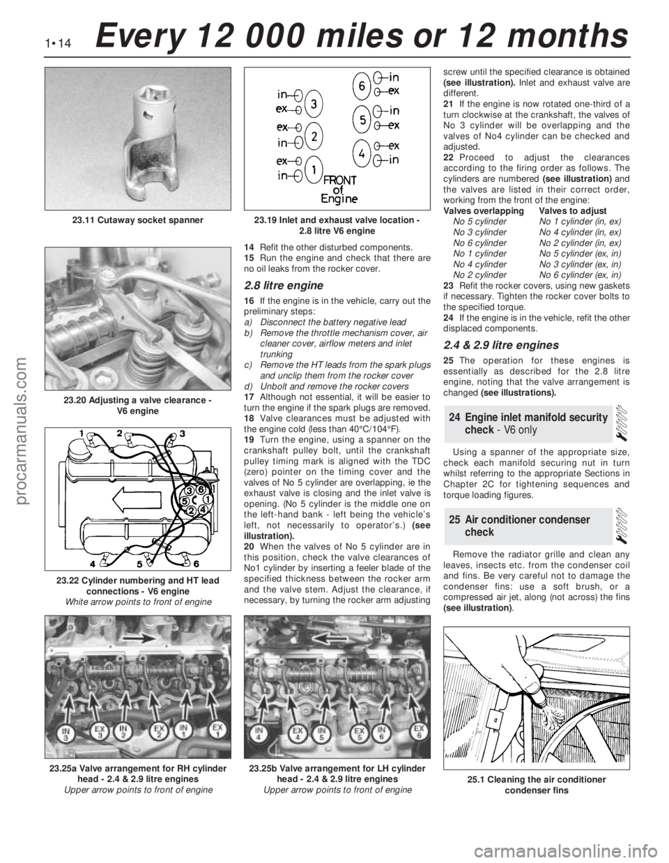
19Turn the engine, using a spanner on the
crankshaft pulley bolt, until the crankshaft
pulley timing mark is aligned with the TDC
(zero) pointer on the timing cover and the
valves of No 5 cylinder are overlapping, ie the
exhaust valve is closing and the inlet valve is
opening. (No 5 cylinder is the middle one on
the left-hand bank - left being the vehicle’s
left, not necessarily to operator’s.) (see
illustration).
20When the valves of No 5 cylinder are in
this position, check the valve clearances of
No1 cylinder by inserting a feeler blade of the
specified thickness between the rocker arm
and the valve stem. Adjust the clearance, if
necessary, by turning the rocker arm adjustingscrew until the specified clearance is obtained
(see illustration).Inlet and exhaust valve are
different.
21If the engine is now rotated one-third of a
turn clockwise at the crankshaft, the valves of
No 3 cylinder will be overlapping and the
valves of No4 cylinder can be checked and
adjusted.
22Proceed to adjust the clearances
according to the firing order as follows. The
cylinders are numbered (see illustration)and
the valves are listed in their correct order,
working from the front of the engine:
Valves overlappingValves to adjust
No 5 cylinderNo 1 cylinder (in, ex)
No 3 cylinderNo 4 cylinder (in, ex)
No 6 cylinderNo 2 cylinder (in, ex)
No 1 cylinderNo 5 cylinder (ex, in)
No 4 cylinderNo 3 cylinder (ex, in)
No 2 cylinderNo 6 cylinder (ex, in)
23Refit the rocker covers, using new gaskets
if necessary. Tighten the rocker cover bolts to
the specified torque.
24If the engine is in the vehicle, refit the other
displaced components.
2.4 & 2.9 litre engines
25The operation for these engines is
essentially as described for the 2.8 litre
engine, noting that the valve arrangement is
changed (see illustrations).
Using a spanner of the appropriate size,
check each manifold securing nut in turn
whilst referring to the appropriate Sections in
Chapter 2C for tightening sequences and
torque loading figures.
Remove the radiator grille and clean any
leaves, insects etc. from the condenser coil
and fins. Be very careful not to damage the
condenser fins: use a soft brush, or a
compressed air jet, along (not across) the fins
(see illustration).
25Air conditioner condenser
check
24Engine inlet manifold security
check - V6 only
1•14Every 12 000 miles or 12 months
23.19 Inlet and exhaust valve location -
2.8 litre V6 engine
23.20 Adjusting a valve clearance -
V6 engine
23.11 Cutaway socket spanner
23.25a Valve arrangement for RH cylinder
head - 2.4 & 2.9 litre engines
Upper arrow points to front of engine23.25b Valve arrangement for LH cylinder
head - 2.4 & 2.9 litre engines
Upper arrow points to front of engine
23.22 Cylinder numbering and HT lead
connections - V6 engine
White arrow points to front of engine
25.1 Cleaning the air conditioner
condenser fins
procarmanuals.com
Page 16 of 255
1Remove the radiator grille being careful not
to damage the condenser fins.
2Check the refrigerant charge as follows. The
engine should be cold and the ambient
temperature should be between 18°and 25°C
(64°and 77°F).
3Start the engine and allow it to idle. Observe
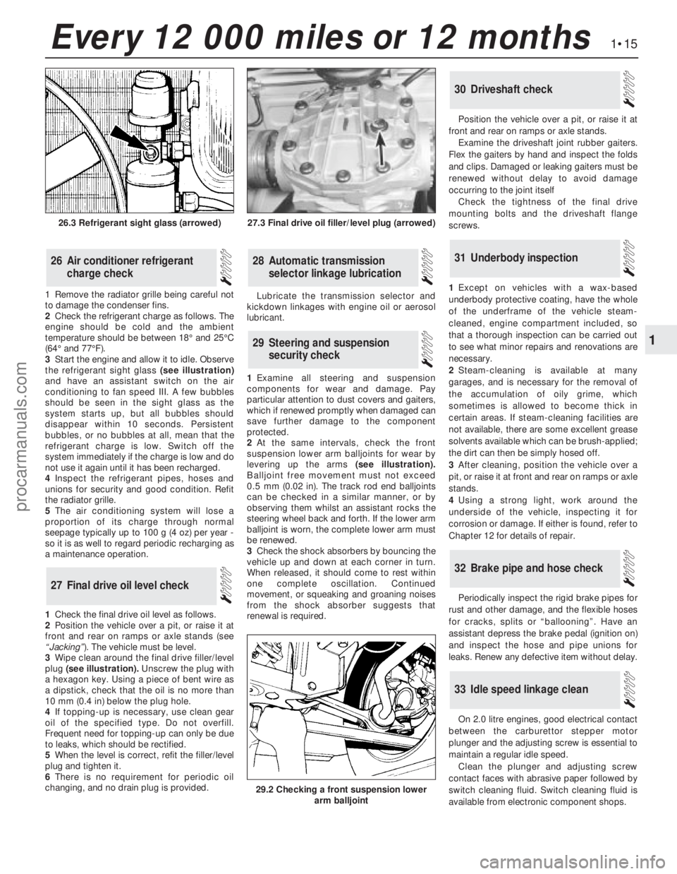
the refrigerant sight glass(see illustration)
and have an assistant switch on the air
conditioning to fan speed III. A few bubbles
should be seen in the sight glass as the
system starts up, but all bubbles should
disappear within 10 seconds. Persistent
bubbles, or no bubbles at all, mean that the
refrigerant charge is low. Switch off the
system immediately if the charge is low and do
not use it again until it has been recharged.
4Inspect the refrigerant pipes, hoses and
unions for security and good condition. Refit
the radiator grille.
5The air conditioning system will lose a
proportion of its charge through normal
seepage typically up to 100 g (4 oz) per year -
so it is as well to regard periodic recharging as
a maintenance operation.
1Check the final drive oil level as follows.
2Position the vehicle over a pit, or raise it at
front and rear on ramps or axle stands (see
“Jacking”). The vehicle must be level.
3Wipe clean around the final drive filler/level
plug (see illustration).Unscrew the plug with
a hexagon key. Using a piece of bent wire as
a dipstick, check that the oil is no more than
10 mm (0.4 in) below the plug hole.
4If topping-up is necessary, use clean gear
oil of the specified type. Do not overfill.
Frequent need for topping-up can only be due
to leaks, which should be rectified.
5When the level is correct, refit the filler/level
plug and tighten it.
6There is no requirement for periodic oil
changing, and no drain plug is provided. Lubricate the transmission selector and
kickdown linkages with engine oil or aerosol
lubricant.
1Examine all steering and suspension
components for wear and damage. Pay
particular attention to dust covers and gaiters,
which if renewed promptly when damaged can
save further damage to the component
protected.
2At the same intervals, check the front
suspension lower arm balljoints for wear by
levering up the arms(see illustration).
Balljoint free movement must not exceed
0.5 mm (0.02 in). The track rod end balljoints
can be checked in a similar manner, or by
observing them whilst an assistant rocks the
steering wheel back and forth. If the lower arm
balljoint is worn, the complete lower arm must
be renewed.
3Check the shock absorbers by bouncing the
vehicle up and down at each corner in turn.
When released, it should come to rest within
one complete oscillation. Continued
movement, or squeaking and groaning noises
from the shock absorber suggests that
renewal is required.Position the vehicle over a pit, or raise it at
front and rear on ramps or axle stands.
Examine the driveshaft joint rubber gaiters.
Flex the gaiters by hand and inspect the folds
and clips. Damaged or leaking gaiters must be
renewed without delay to avoid damage
occurring to the joint itself
Check the tightness of the final drive
mounting bolts and the driveshaft flange
screws.
1Except on vehicles with a wax-based
underbody protective coating, have the whole
of the underframe of the vehicle steam-
cleaned, engine compartment included, so
that a thorough inspection can be carried out
to see what minor repairs and renovations are
necessary.
2Steam-cleaning is available at many
garages, and is necessary for the removal of
the accumulation of oily grime, which
sometimes is allowed to become thick in
certain areas. If steam-cleaning facilities are
not available, there are some excellent grease
solvents available which can be brush-applied;
the dirt can then be simply hosed off.
3After cleaning, position the vehicle over a
pit, or raise it at front and rear on ramps or axle
stands.
4Using a strong light, work around the
underside of the vehicle, inspecting it for
corrosion or damage. If either is found, refer to
Chapter 12 for details of repair.
Periodically inspect the rigid brake pipes for
rust and other damage, and the flexible hoses
for cracks, splits or “ballooning”. Have an
assistant depress the brake pedal (ignition on)
and inspect the hose and pipe unions for
leaks. Renew any defective item without delay.
On 2.0 litre engines, good electrical contact
between the carburettor stepper motor
plunger and the adjusting screw is essential to
maintain a regular idle speed.
Clean the plunger and adjusting screw
contact faces with abrasive paper followed by
switch cleaning fluid. Switch cleaning fluid is
available from electronic component shops.
33Idle speed linkage clean
32Brake pipe and hose check
31Underbody inspection
30Driveshaft check
29Steering and suspension
security check
28Automatic transmission
selector linkage lubrication
27Final drive oil level check
26Air conditioner refrigerant
charge check
1•15
1
Every 12 000 miles or 12 months
27.3 Final drive oil filler/level plug (arrowed)
29.2 Checking a front suspension lower
arm balljoint
26.3 Refrigerant sight glass (arrowed)
procarmanuals.com
Page 20 of 255
the previous sub Section.
27Refitting is a reversal of removal, ensuring
that the rotor arm is pushed fully home on the
rotor shaft. Make sure that the HT leads are
fitted to their correct cylinders. Note that the
rotor arm will only fit in one position.
Note: A brake band torque wrench - Ford tool
No 17-005, or equivalent - will be required for
this job.
1Raise and support the front of the vehicle.
2Disconnect the downshift (kickdown) cable
from the transmission when so equipped.
3Release the locknuts on the two brake band
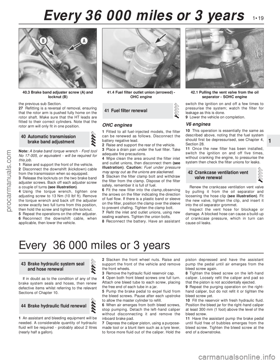
adjuster screws. Back off each adjuster screw
a couple of turns (see illustration).
4Using the torque wrench, tighten one
adjusting screw to 13 Nm (10 lbf ft). Remove
the torque wrench and back off the adjuster
screw exactly two full turns from this position,
then hold the screw and tighten the locknut.
5Repeat the operations on the other adjuster.
6Reconnect the downshift cable, when
applicable, then lower the vehicle.
OHC engines
1Fitted to all fuel-injected models, the filter
can be renewed as follows. Disconnect the
battery negative lead.
2Raise and support the rear of the vehicle.
3Place a drain pan under the fuel filter. Take
adequate fire precautions.
4Wipe clean the area around the filter inlet
and outlet unions, then disconnect them (see
illustration). Caution: Fuel under pressure
may spray out as the unions are slackened.
5Slacken the filter clamp bolt and withdraw
the filter from the clamp. Dispose of the filter
safely, remember it is full of fuel.
6Fit the new filter into the clamp,observing
the arrows on the filter indicating the direction
of fuel flow. If there is a plastic band or sleeve
on the filter, position the clamp over the sleeve
to prevent chafing. Tighten the clamp bolt.
7Refit the inlet and outlet unions, using new
sealing washers. Tighten the union bolts.
8Reconnect the battery. Have an assistantswitch the ignition on and off a few times to
pressurise the system; watch the filter for
leakage as this is done.
9Lower the vehicle on completion.
V6 engines
10This operation is essentially the same as
described above, noting that the fuel system
should first be depressurised, see Chapter 4,
Section 28.
11Once the new filter has been installed,
switch the ignition on and off five times,
without cranking the engine, to pressurise the
system then check the filter unions for leaks.
Renew the crankcase ventilation vent valve
by pulling it from the oil separator and
loosening the hose clip (see illustration). Fit
the new valve, tighten the clip, and insert it
into the oil separator grommet.
Inspect the vent hose for blockage or
damage. A blocked hose can cause a build-up
of crankcase pressure, which in turn can
cause oil leaks.
42Crankcase ventilation vent
valve renewal
41Fuel filter renewal
40Automatic transmission
brake band adjustment
1•19
1
Every 36 000 miles or 3 years
41.4 Fuel filter outlet union (arrowed) -
OHC engine42.1 Pulling the vent valve from the oil
separator - SOHC engine40.3 Brake band adjuster screw (A) and
locknut (B)
If in doubt as to the condition of any of the
brake system seals and hoses, then renew
defective items whilst referring to the relevant
Sections of Chapter 10.
1An assistant andbleeding equipment will be
needed. A considerable quantity of hydraulic
fluid will be required - probably about 2 litres
(nearly half a gallon).2Slacken the front wheel nuts. Raise and
support the front of the vehicle andremove
the front wheels.
3Remove the hydraulic fluid reservoir cap.
4Open both front bleed screws one full turn.
Attach one bleed tube to each screw, placing
the free end of each tube in a jar.
5Pump the brake pedal to expel fluid from
the bleed screws. Pause after each upstroke
to allow the master cylinder to refill.
6When air emerges from both bleed screws,
stop pumping. Detach the left-hand caliper
without disconnecting it and remove the
inboard brake pad.
7Depress the caliper piston, using a purpose-
made tool or a blunt item such as a tyre lever,
to force more fluid out of the caliper. Hold thepiston depressed and have the assistant
pump the pedal until air emerges from the
bleed screw again.
8Tighten the bleed screw on the left-hand
caliper. Loosely refit the caliper and pad so
that the piston is not accidentally ejected.
9Repeat the purging operation on the right-
hand caliper, but do not refit it or tighten the
bleed screw yet.
10Fill the reservoir with fresh hydraulic fluid.
Position the bleed jar for the right-hand caliper
at least 300 mm (1 foot) above the level of the
bleed screw.
11Have the assistant pump the brake pedal
until fluid free of bubbles emerges from the
bleed screw. Tighten the bleed screw at the
end of a downstroke.
44Brake hydraulic fluid renewal
43Brake hydraulic system seal
and hose renewal
Every 36 000 miles or 3 years
procarmanuals.com
Page 21 of 255
12Place a piece of wood in the caliper jaws
to limit piston travel. Keep your fingers clear of
the piston. Have the assistant depress the
brake pedal gentlyin order to move the
caliper piston out.
13With the pedal held depressed, slacken
the bleed screw on the right-hand caliper and
again depress the piston. Tighten the bleed
screw when the piston is retracted. The pedal
can now be released.
14Disconnect the bleed tube. Refit the right-hand brake pad and caliper.
15Remove the left-hand caliper and inboard
pad again. Carry out the operations described
in paragraphs 10 to 14 on the left-hand
caliper.
16Bleed the rear brakes as described in
Chapter 10.
17Refit the front wheels, lower the vehicle
and tighten the wheel nuts.
18Pump the brake pedal to bring the pads
up to the discs, then make a final check of thehydraulic fluid level. Top-up and refit the
reservoir cap.
Camshaft drivebelt renewal is
recommended as a precautionary measure.
Refer to Chapter 2, Part A, Sections 13 and 45
for the full renewal procedure.
45Camshaft drivebelt renewal -
SOHC engines
1Before proceeding, note the precautions
given in Chapter 3, Section 1.
2Disconnect the battery negative lead.
3Remove the expansion tank cap. Take
precautions against scalding if the system is
hot.
4Place a drain pan of adequate capacity
beneath the radiator drain plug. Unscrew the
plug, without removing it, and allow the
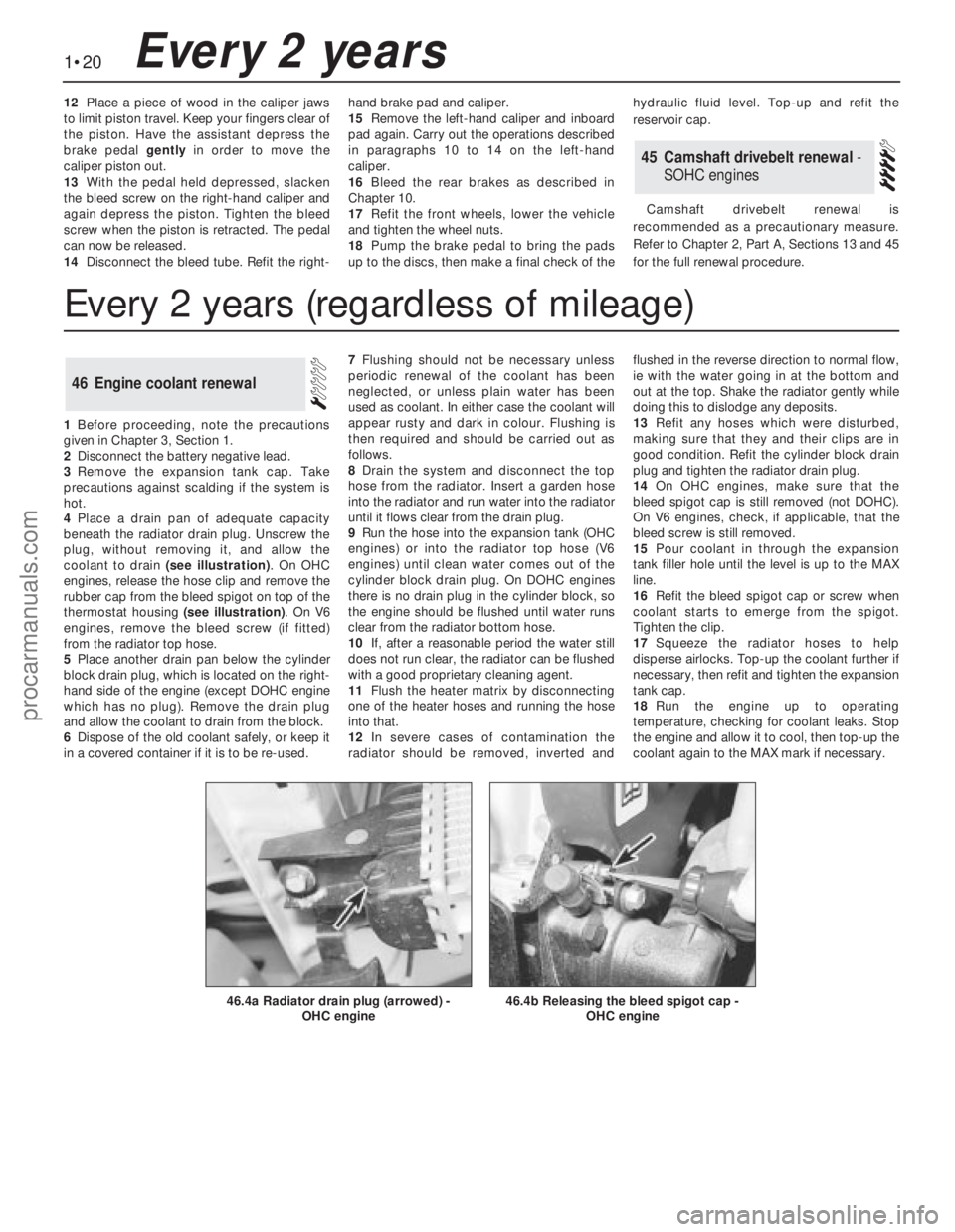
coolant to drain (see illustration). On OHC
engines, release the hose clip and remove the
rubber cap from the bleed spigot on top of the
thermostat housing (see illustration). On V6
engines, remove the bleed screw (if fitted)
from the radiator top hose.
5Place another drain pan below the cylinder
block drain plug, which is located on the right-
hand side of the engine (except DOHC engine
which has no plug). Remove the drain plug
and allow the coolant to drain from the block.
6Dispose of the old coolant safely, or keep it
in a covered container if it is to be re-used.7Flushing should not be necessary unless
periodic renewal of the coolant has been
neglected, or unless plain water has been
used as coolant. In either case the coolant will
appear rusty and dark in colour. Flushing is
then required and should be carried out as
follows.
8Drain the system and disconnect the top
hose from the radiator. Insert a garden hose
into the radiator and run water into the radiator
until it flows clear from the drain plug.
9Run the hose into the expansion tank (OHC
engines) or into the radiator top hose (V6
engines) until clean water comes out of the
cylinder block drain plug. On DOHC engines
there is no drain plug in the cylinder block, so
the engine should be flushed until water runs
clear from the radiator bottom hose.
10If, after a reasonable period the water still
does not run clear, the radiator can be flushed
with a good proprietary cleaning agent.
11Flush the heater matrix by disconnecting
one of the heater hoses and running the hose
into that.
12In severe cases of contamination the
radiator should be removed, inverted andflushed in the reverse direction to normal flow,
ie with the water going in at the bottom and
out at the top. Shake the radiator gently while
doing this to dislodge any deposits.
13Refit any hoses which were disturbed,
making sure that they and their clips are in
good condition. Refit the cylinder block drain
plug and tighten the radiator drain plug.
14On OHC engines, make sure that the
bleed spigot cap is still removed (not DOHC).
On V6 engines, check, if applicable, that the
bleed screw is still removed.
15Pour coolant in through the expansion
tank filler hole until the level is up to the MAX
line.
16Refit the bleed spigot cap or screw when
coolant starts to emerge from the spigot.
Tighten the clip.
17Squeeze the radiator hoses to help
disperse airlocks. Top-up the coolant further if
necessary, then refit and tighten the expansion
tank cap.
18Run the engine up to operating
temperature, checking for coolant leaks. Stop
the engine and allow it to cool, then top-up the
coolant again to the MAX mark if necessary.
46Engine coolant renewal
1•20Every 2 years
46.4b Releasing the bleed spigot cap -
OHC engine46.4a Radiator drain plug (arrowed) -
OHC engine
Every 2 years (regardless of mileage)
procarmanuals.com
Page 28 of 255
The cylinder head is of crossflow design
with the inlet manifold mounted on the left-
hand side and the exhaust manifold mounted
on the right-hand side.
Lubrication is by means of a bi-rotor pump
which draws oil through a strainer located
inside the sump, and forces it through a full-
flow filter into the engine oil galleries where it
is distributed to the crankshaft, camshaft and
auxiliary shaft. The big-end bearings are
supplied with oil via internal drillings in the
crankshaft.The undersides of the pistons are
supplied with oil from drillings in the big-ends.
The distributor shaft is intermittently supplied
with oil from the drilled auxiliary shaft. The
camshaft and cam followers are supplied with
oil via a drilled spray tube from the centre
camshaft bearing.
A semi-closed crankcase ventilation system
is employed whereby piston blow-by gases
are drawn into the inlet manifold via an oil
separator and on carburettor models a control
valve.
The following operations can be carried out
without removing the engine, although the
work may be easier and quicker with the
engine removed:
a)Removal and refitting of the cylinder head
b)Removal and refitting of the camshaft
(after removing the cylinder head)
c)Removal and refitting of the timing belt
and sprockets
d)Removal and refitting of the sump and oil
pump
e)Removal and refitting of the pistons,
connecting rods and big-end bearings
f)Renewal of the engine mountings
g)Renewal of the crankshaft oil seals
h)Removal and refitting of the auxiliary shaft
j)Removal and refitting of the flywheel
The engine must be removed from the
vehicle for the following operations:
a)Renewal of the crankshaft main bearings
b)Removal and refitting of the crankshaft
The engine may be lifted out either on its
own or together with the gearbox. Unless work
is also necessary on the gearbox it is
recommended that the engine is removed on
its own. Where automatic transmission is
fitted, the engine should be removed on its
own owing to the additional weight. If the
engine and gearbox are removed together,
they will have to be tilted at a very steep angle;
make sure that the range of the lifting tackle is
adequate.1Disconnect the battery negative lead.
2Remove the bonnet.
3On carburettor models, remove the air
cleaner. On fuel-injection models, remove the
air cleaner cover, vane airflow meter and air
inlet trunking.
4If a splash guard is fitted, remove it.
5Release the securing clips and bolts and
remove the upper half of the fan shroud. On
carburettor models remove the lower half of
the shroud too.
6Drain the cooling system.
7Disconnect the radiator top and bottom
hoses from the thermostat housing and water
pump. Disconnect the top hose spur from the
expansion tank and unclip it.
8Disconnect the heater hoses from the water
pump and from the inlet manifold or automatic
choke housing. Unclip the hoses.
9On models with power steering, remove the
steering pump.
10Disconnect the vacuum pipe(s) from the
inlet manifold, labelling them if there is any
possibility of confusion.
11Disconnect the following wiring, as
applicable:
a)Alternator
b)Temperature gauge sender
c)Engine management temperature sensor
d)Distributor
e)Oil pressure switch
f)Automatic choke and thermo-switch
g)Carburettor stepper motor
h)Fuel-injection system sub-harness
j)Inlet manifold heater
12Disconnect the HT lead from the coil.
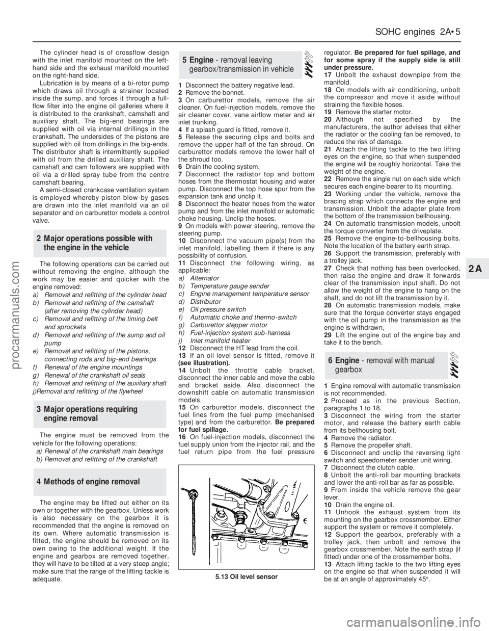
13If an oil level sensor is fitted, remove it
(see illustration).
14Unbolt the throttle cable bracket,
disconnect the inner cable and move the cable
and bracket aside. Also disconnect the
downshift cable on automatic transmission
models.
15On carburettor models, disconnect the
fuel lines from the fuel pump (mechanised
type) and from the carburettor. Be prepared
for fuel spillage.
16On fuel-injection models, disconnect the
fuel supply union from the injector rail, and the
fuel return pipe from the fuel pressureregulator. Be prepared for fuel spillage, and
for some spray if the supply side is still
under pressure.
17Unbolt the exhaust downpipe from the
manifold.
18On models with air conditioning, unbolt
the compressor and move it aside without
straining the flexible hoses.
19Remove the starter motor.
20Although not specified by the
manufacturers, the author advises that either
the radiator or the cooling fan be removed, to
reduce the risk of damage.
21Attach the lifting tackle to the two lifting
eyes on the engine, so that when suspended
the engine will be roughly horizontal. Take the
weight of the engine.
22Remove the single nut on each side which
secures each engine bearer to its mounting.
23Working under the vehicle, remove the
bracing strap which connects the engine and
transmission. Unbolt the adapter plate from
the bottom of the transmission bellhousing.
24On automatic transmission models, unbolt
the torque converter from the driveplate.
25Remove the engine-to-bellhousing bolts.
Note the location of the battery earth strap.
26Support the transmission, preferably with
a trolley jack.
27Check that nothing has been overlooked,
then raise the engine and draw it forwards
clear of the transmission input shaft. Do not
allow the weight of the engine to hang on the
shaft, and do not lift the transmission by it.
28On automatic transmission models, make
sure that the torque converter stays engaged
with the oil pump in the transmission as the
engine is withdrawn,
29Lift the engine out of the engine bay and
take it to the bench.
1Engine removal with automatic transmission
is not recommended.
2Proceed as in the previous Section,
paragraphs 1 to 18.
3Disconnect the wiring from the starter
motor, and release the battery earth cable
from its bellhousing bolt.
4Remove the radiator.
5Remove the propeller shaft.
6Disconnect and unclip the reversing light
switch and speedometer sender unit wiring.
7Disconnect the clutch cable.
8Unbolt the anti-roll bar mounting brackets
and lower the anti-roll bar as far as possible.
9From inside the vehicle remove the gear
lever.
10Drain the engine oil.
11Unhook the exhaust system from its
mounting on the gearbox crossmember. Either
support the system or remove it completely.
12Support the gearbox, preferably with a
trolley jack, then unbolt and remove the
gearbox crossmember. Note the earth strap (if
fitted) under one of the crossmember bolts.
13Attach lifting tackle to the two lifting eyes
on the engine so that when suspended it will
be at an angle of approximately 45°.
6Engine - removal with manual
gearbox
5Engine - removal leaving
gearbox/transmission in vehicle
4Methods of engine removal
3Major operations requiring
engine removal
2Major operations possible with
the engine in the vehicle
SOHCengines 2A•5
2A
5.13 Oil level sensor
procarmanuals.com
Page 35 of 255
mountings to the front crossmember. Recover
the washers.
3Raise the engine with a hoist or a suitable
protected jack until the mountings are free,
then remove them.
4Fit the new mountings and lower the engine
onto them.
5Fit the nuts and washers and tighten the
nuts.
6Lower the vehicle.
Carburettor models
The crankcase ventilation system consists
of the special oil filter cap (containing a steel
wool filter) and an oil separator and vent valve
on the left-hand side of the engine. This is
connected by hose to the inlet manifold. The
system operates according to the vacuum in
the inlet manifold. Air is drawn through the
filler cap, through the crankcase, and then
together with piston blow-by gasses through
the oil separator and vent valve to the inlet
manifold. The blow-by gases are then drawn
into the engine together with the fuel/air
mixture. Refer to Chapter 1 for maintenance of
the system.
Fuel-injection models
This system is closed, consisting of an oilseparator on the left-hand side of the engine
and a hose connecting it to the inlet air
trunking. Because the trunking is not subject
to manifold vacuum, no vent valve is needed.
1With the engine completely stripped, clean
all the components and examine them for
wear. Each part should be checked, and
where necessary renewed or renovated as
described in the following Sections. Renew
main and big end shell bearings as a matter of
course, unless you know that they have had
little wear and are in perfect condition.
2If in doubt as to whether to renew a
component which is still just serviceable,
consider the time and effort which will be
incurred should it fail at an early date.
Obviously the age and expected life of the
vehicle must influence the standards applied.
3Gaskets, oil seals and O-rings must all be
renewed as a matter of routine. Flywheel and
cylinder head bolts must be renewed because
of the high stresses to which they are
subjected.
4Take the opportunity to renew the engine
core plugs while they are easily accessible.
Knock out the old plugs with a hammer and
chisel or punch. Clean the plug seats, smear
the new plugs with sealant and tap them
squarely into position.1Unscrew the bolts and remove the oil pump
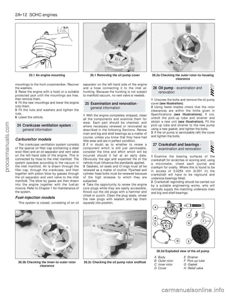
cover (see illustration).
2Using feeler blades check that the rotor
clearances are within the limits given in
Specifications (see illustrations). If not,
unbolt the pick-up tube and strainer and
obtain a new unit (see illustration).Fit the
pick-up tube and strainer to the new pump
using a new gasket, and tighten the bolts.
3If the oil pump is serviceable refit the cover
and tighten the bolts.
1Examine the bearing surfaces of the
crankshaft for scratches or scoring and, using
a micrometer, check each journal and
crankpin for ovality. Where this is found to be
in excess of 0.0254 mm (0.001 in) the
crankshaft will have to be reground and
undersize bearings fitted.
2Crankshaft regrinding should be carried out
by a suitable engineering works, who will
normally supply the matching undersize main
and big-end shell bearings.
27Crankshaft and bearings -
examination and renovation
26Oil pump - examination and
renovation
25Examination and renovation -
general information
24Crankcase ventilation system -
general information
2A•12SOHCengines
23.1 An engine mounting
26.2b Checking the inner-to-outer rotor
clearance26.2c Checking the oil pump rotor endfloat
26.2d Exploded view of the oil pump
A Body
B Outer rotor
C Inner rotor
D CoverE Strainer
F Pick-up tube
G Gasket
H Relief valve
26.1 Removing the oil pump cover26.2a Checking the outer rotor-to-housing
clearance
procarmanuals.com