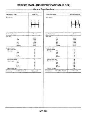
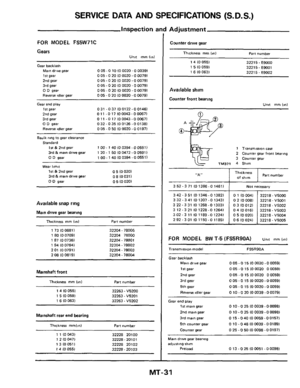
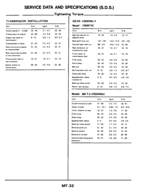
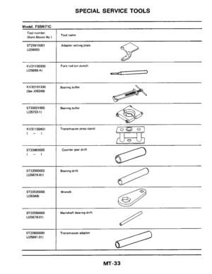
Page 17 of 34
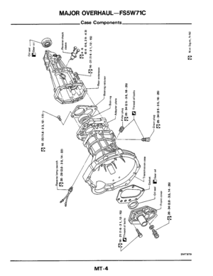
REPAIR FOR COMPONENT PARTS-FS5W71C
Adapter Plate (Cont'd)
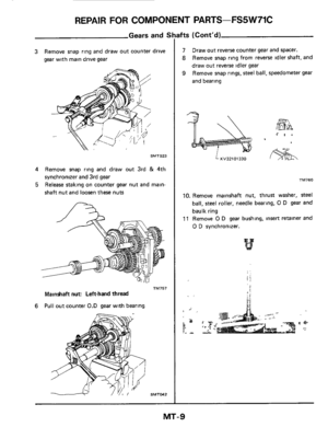
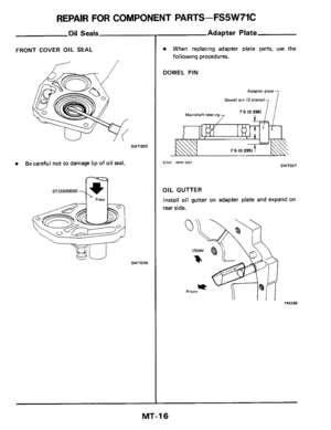
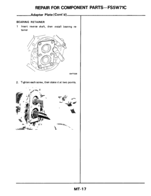
BEARING RETAINER
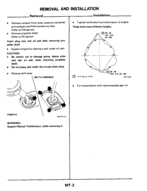
1 Insert reverse shaft, then install bearing re-
tainer
SMTO28
2. Tighten each screw, then stake it at two points.
MT-17
Page 18 of 34
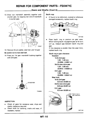
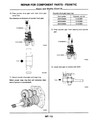
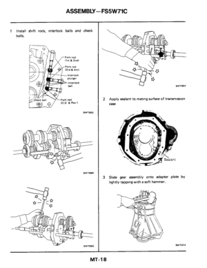
ASSEMBLY -FS5 W71C
1 Install shift rods, interlock balls and check
balls.
SMT992
SMT989
SMT990
U SMT991
2 Apply sealant to mating surface of transmission
case
3 Slide gear assembly onto adapter plate by
lightly tapping with a soft hammer.
SMT013
MT-18
Page 19 of 34
ASSEMBLY - FS5W71C
-
' A'
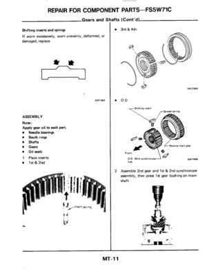
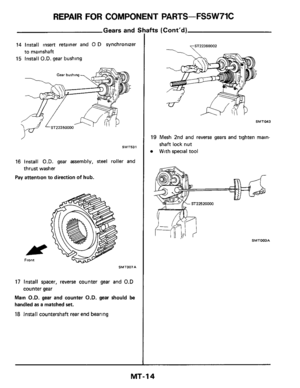
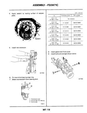
4 Apply sealant to mating surface of adapter
plate.
Thickness of shim Part number
5 Install rear extension
01 (00041 342-3 51
(0 1346-0 13821
3 32-341
10 1307 -0 13431
3 22-331
10 1268-0 13031
312-321
(0 1228 - 0 12641
302-311
(01189-01224)
2 92 -3 01
(0 1150 - 0 11851
0 2 10 0081
-
03 I00121
-
0 4 10 0161
-
0 5 IO 0201
-
0 6 (0 0241
SMT993
32218-VM00
3221 8-VM01
32218-V5002
32218-VMO3
32218-VMO4
32218-V5005
6. Fit main drive bearing snap ring.
7 Select countershaft front bearing shim
2
3
Transrnoss~on case
Counter gear front bearing counrer gear
TM371
352 371 10 1386 0 14611 Not necessary
8
9
Install gasket and front cover.
Install bolts and plunger shown below
MT-19
Page 20 of 34
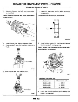
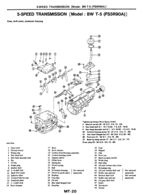
![NISSAN 300ZX 1984 Z31 Manual Transmission Workshop Manual 5-SPEED TRANSMISSION [Model: BW T-5 (FS5R90A)l
5-SPEED TRANSMISSION [Model : BW T-5 (FS5R90A)]
Case. shift cover, extension housing
Tightening torque [N m 1kg-m.ff-lbll
2 Neutral witch 20 - 29 1](/manual-img/5/575/w960_575-19.png "NISSAN 300ZX 1984 Z31 Manual Transmission Workshop Manual 5-SPEED TRANSMISSION [Model: BW T-5 (FS5R90A)l
5-SPEED TRANSMISSION [Model : BW T-5 (FS5R90A)]
Case. shift cover, extension housing
Tightening torque [N m 1kg-m.ff-lbll
2 Neutral witch 20 - 29 1")
5-SPEED TRANSMISSION [Model: BW T-5 (FS5R90A)l
5-SPEED TRANSMISSION [Model : BW T-5 (FS5R90A)]
Case. shift cover, extension housing
Tightening torque [N m 1kg-m.ff-lbll
2 Neutral witch 20 - 29 12 0.3 0, 14 - 221
4 Hex head bolt 8.1 - 14 7 10 83 - 1 5,6.0.10 81 5 Hex head shoulder bolt 8 1 - 14 7 IO 83.1 5.6 0 -
20 Control housing rrew 15 - 27 11 5 - 2 8.11 - 201
31 Hex head flanged bolt 27 - 62 12.8.6 3,20 .461
36 Pivot pin 21 -33 12 1 -34, 15-25)
37 Bad-up lamp
witch 17 - 24 11.7 .2.4.12.171
Drain plug 20 .34 (2.0.3 5, 14 - 251 SMT846
1 Casecwer
2 Neutralswltch
3 Wmgcbp 4 Hexheadbolt
5 Hex head shoulder bolt
6h 7 0-nng
8 Welshplug
9 Shfter shaft 10 3-4 Mtfork 11 swt fork msert
12 Selector plate 13 Control seiector ann
14 Interlock plate I5 I-Zshrft fork
16 Boot retamer
10 81
17 Boot 18 Boot retamer
19 Control Iever/housng assembly 20 Control houmg screw
21 Dampersleeve
22 Offset lever 23 Spmg-pm
24 Detentspmg
25 Ball
26 Extennon housmg Not sewiced 27 Detent & guide plate ! separately
28 Bushmg
29 Cup plug 30 01Iseal
31 Hex head flanged bolt
32 Breath
Mi-20
33 Case 34 Magnet 35 cllp 36 Plvatpm
37 Back-up lamp swtch
38 Welsh plug
39 Plpeplug 40 5th and reverse relay lever
42 5th and ~everse rhrft rad Not sernced
separately
Not se~ced
separately
41 Retammgmg
43 Roller cam and pm
44 Reverse duft fork
4$ Roller cam and pm
46 5th gear duft fork 47 Insert
48 Spring-pin 49 sprmg
!
Page 21 of 34
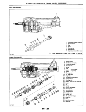
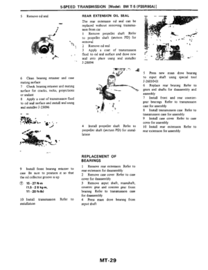
5SPEED TRANSMISSION [Model: BW T-5 (FS5R90A)I
Input shaft assembly
n
1 Input shaft bearmg retamer 2 Hex headbolt
3
Seal
4 Stum 5 Bearmgcup
6 Bearmgcone
7 Input shaft
(mam drive gear)
ZlHex head bolt1 15-27N.rnl15-Z8kgrn,11 -20ft-lbl
Output shaft assembly
n
iMT848
1 Needle rollers
2 Needle thrust bearmg
3 Thrustbearmgrace
4 Blockngnng
5 SPnng
9 Blo&ngnng
10 3rdspeedgea1
12 2nd speed thrust washer
13 Zndspeedgear
14 Blockngnng
15 Output
shaft and hub assembly
16 Insert
17
F’m
18 SPW
19 Reverse shdmg gear
20 Block~ngimg
21 lstspeedgear
22 Thm$washer
23 Bearmgcone
24 Beanngcup
25 5th speed &wen gear
26 S~pmg
27 BaJ
28 Speedometer
gear
29 S~pnng
11 SMP IUlg
MT-21
Page 22 of 34
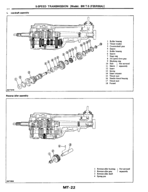
5SPEED TRANSMISSION [Model: BW T-5 (FS5R90A)l -1
C aterrhaft assembly
1 Rollerbearmg
2 Thrustwasha
3 Countershaft gear
4 Spacer
5 Rollerbeanng
6 Spacer I snapnng
8 5th speed drlve gear
9 Blockrngrmg
10 Hub Notsmced
11 Sleeve 1 separately 12 lnmt
14 Insert retamer
16 Needle thrust bearmg
18 Funnel
13 SP~
IS Thrust race
17 Thrustrace
Reverse idler assembly
n
1 Reverse idler bushmg Not ~e~ced
2 Rwase idler gear
3 Rwersetdler shaft 1 separately
4 Spnngpm
UT850
MT-22
Page 23 of 34
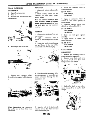
l
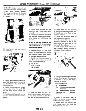
REAR EXTENSION
DISASSEMBLY
1
2 Drain oil
3
damper sleeve
Wipe off drt and grease
Remove sluft lever assembly and
4 Remove pm from offset")
5SPEED TRANSMISSION [Model: BW T-5 (FS5R90A)l
REAR EXTENSION
DISASSEMBLY
1
2 Drain oil
3
damper sleeve
Wipe off drt and grease
Remove sluft lever assembly and
4 Remove pm from offset lever
-.. - ._
'.* .I El
-.. n
5 Remove rear extension, offset
lever, detent
spnng and ball by tappmg
it
7
When disassembling rear extension,
be careful not to lose thrust race
and funnel.
INSPECTION
1 Clean with solvent and check for
cracks
2 Check mating surface of rear
extension for small nicks, prolec-
tions or sealant
If the rear extension bushing or guide
plate are worn, cracked or broken,
replace them as an assembly of bush-
ing, guide plate and rear extension
housing.
ASSEMBLY
1 Clean matmg surfaces of case and
rear extension
2 Apply a contmuous bead of
sealant to the matmg surface of the
case
3 Retam the needle thrust bearmg,
race and funnel
to the rear of the
countershaft with Petroleum Jelly
4 Place detent ball, spnng and offset
lever mto position on guide plate and
install extension houslng to the
transmission case
5 Ahgn the hole ?n the shifter shaft
with the hole
m the offset lever and
mstall the retammg pm
MT-23
6 Install rear extenQon bolts to
transmission case
0 : 27 - 62 Nm
(2 8 -6 3 kg-m,
20 - 46 ft-lb)
7 Apply a contmuous bead of
sealant to shlft cover opening of
rear extension
8 Assemble damper sleeve mto
offset lever and install shlft lever
@ :20-34Nm
(2.0 - 3.5 kgm,
14 .25 ft-lb)
9 Make sure that gears operate
smoothly
10 Apply sealant to thread and
install dram plug
0.20 - 34 N m
(2 0 - 3.5 kg-m,
14
- 25 ft-lb)
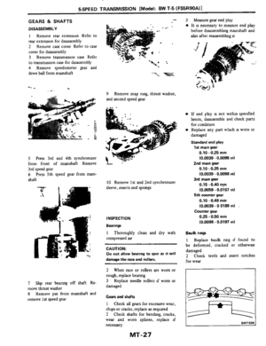
CASE COVER
DISASSEMBLY
1 Remove rear extension Refer to
rear extension for disassembly
2 Remove cover bolts and cover
by tapping it with dnver Shde cover
to nght side of case and hft
3 Pull shifter shaft to rear and re-
move stnkmg lever to shlfter shaft
roll pm
Page 24 of 34
I
4 Remove shifter shaft through rear
of case cover
5 Slide selector plates from shift
fork assembhes
. __ - - . . I
INSPECTION
1 Clean with")
5SPEED TRANSMISSION [Model: BW T-5 (FS5R90A)I
4 Remove shifter shaft through rear
of case cover
5 Slide selector plates from shift
fork assembhes
. __ - - . . I
INSPECTION
1 Clean with solvent and check for
wear, scratches, projections, damage,
breakage
or other faulty conditions
Replace any part whch is worn or
damaged
2 Inspect shft fork inserts for wear
or damage Replace if necessary
ASSEMBLY
I Assemble selector plates to sluft
fork assembhes
2 Install shifter shaft through open-
mg m rear of case cover and assemble
to
1-2 duft fork, mterlock plate,
strkmg lever and
3-4 sluft fork
Install shfter shaft roll pin
to stnkmg
lever
3 Apply a contmuous bead of
sealant to case cover matlng surface
4 Install cover to case
5 Apply sealant to threads and
install two ahgnment dowels into
cover
6 Apply sealant to threads and
install case cover bolts
@ : 8.1 - 14.7 N m
(0.83 - 1.5 kg-m,
6.0 - 10 8 ft-lb)
7 Install rear extension Refer to
rear extension for assembly
TRANSMISSION CASE
DISASSEMBLY
1 Remove rear extenson Refer to
rear extension for disassembly
2 Remove case cover Refer to case
cover for disassembly
3 Remove back-up hght swltch
4 Remove retamer rmg and pivot
Pm
5 Remove funnel, thrust race, and
needle thrust beanng
6 Remove snap nng and thrust
race from rear
of 5th speed synchro-
nuer hub
MT-24
7 Remove pin from 5th speed hft
fork
8 Remove 5th speed shift fork,
synchronizer and counter gear
9 Remove front bearmg retamer
10 Remove mput shaft and mam
drive gear assembly Position flat area
of mam drive gear toward the counter
gear and remove
through the front
of the case

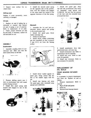

BEARING RETAINER
1 Insert reverse shaft, then install bearing re-
tainer
SMTO28
2. Tighten each screw, then stake it at two points")


I
Input shaft assembly
n
1 Input shaft bearmg retamer 2 Hex headbolt
3
Seal
4 Stum 5 Bearmgcup
6 Bearmgcone
7 Input shaft
(mam drive gear)
Zl")
l -1
C aterrhaft assembly
1 Rollerbearmg
2 Thrustwasha
3 Countershaft gear
4 Spacer
5 Rollerbeanng
6 Spacer I snapnng
8 5th speed drlve gear
9 B")