Page 25 of 34
I
11 Remove mamshaft rear bearmg
race and remove mamshaft assembly
through top of case
I
12 Remove 5th speed shift rad,
reverse fork with")
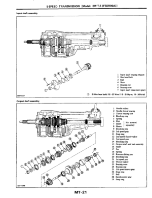
SSPEED TRANSMISSION [Model: BW T-5 (FS5R90A)I
11 Remove mamshaft rear bearmg
race and remove mamshaft assembly
through top of case
I
12 Remove 5th speed shift rad,
reverse fork with 5th and reverse
relay lever, and spnng
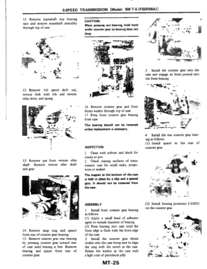
13 Remove pm from reverse idler
shaft Remove reverse idler shaft
and gear
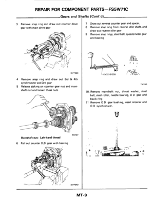
14 Rrmove snap nng and spacer
from rear of counter gear beanng
15. Remove counter gear rear beanng
by pressmg counter gear toward rear
of case untd bearmg is free Remove
bearing and spacer from rear of
counter gear
CAUTION:
When pressing out bearing, hold hand
under counter gear
so bearing does not
drop
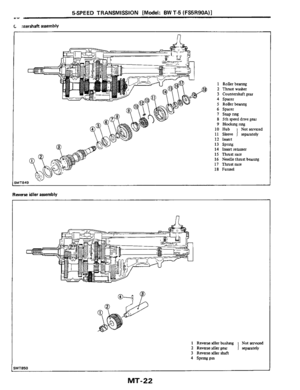
16 Remove counter gear and front
thrust washer through top of case
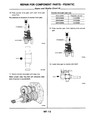
11 Press front counter gear beanng
from case
This bearing should not be removed
unless replacement
is necessary.
INSPECTION
1 Clean with solvent and check for
cracks or pits
2 Check mating surfaces of trans-
mission case for small nicks, projec-
tions or sealant
The magnet at the bottom of the caSe
is held in place by a clip and a special
glue.
It should not be removed from
the case.
ASSEMBLY
1 Install front counter gear beanng
as follows
(1) Apply a
small bead of adheslve
agent to outside dlameter of bearmg
(2) Press bearmg into case untd the
front edge
is flush with the front edge
of the case
2 Install the counter gear thrust
washer into the case being sure
to abgn
the tang with the notch
m the case
Retam the washer
m the case with
a light coat of petroleum jelly
MT-25
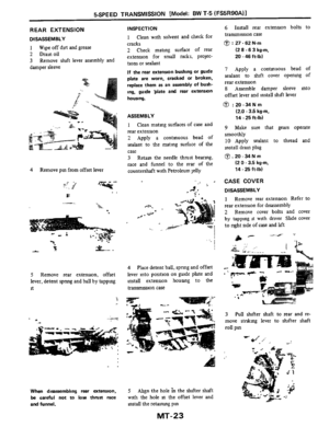
3 Install the counter gear mto the
case and engage its front journal mto
the front bearmg
-' .".-:;-;' . -
.._. .." .
4 Install the rear counter gear bear-
ing as follows
(1) Install spacer to the rear of
counter gear
(2) Install beanng protector 5-33032
on the counter gear
Page 26 of 34
I
(3) Install beanng over protector and
press mto case uslng bearmg mstaller
J-29895 When properly mstalled,
the beanng race
WIU protrude from")
SSPEED TRANSMISSION [Model: BW T-5 (FS5R90A)I
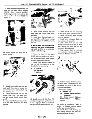
(3) Install beanng over protector and
press mto case uslng bearmg mstaller
J-29895 When properly mstalled,
the beanng race
WIU protrude from the
case
3 12 to 3 22 mm (0 1228 to
0 1268 in)
(4) Install spacer and snap nng at
rear of beanng
5 Install reverse idler gear mto case
with shft fork groove toward the
rear Install reverse idler shaft, 0-rmg
and retammg pm
6 Install reverse fork with 5th and
reverse relay lever, 5th speed sluft
rad and spnng Install backup hght
switch
7 Instal mamshaft assembly mto the
case and mstall mamshaft rear bear-
mg race.
8 Install roller bearmgs mto the
mam drive gear Retaxn with petro-
leum jelly
9 Install mput shaft and
mam drive
gear assembly, needle thrust bearing,
thrust bearmg race and bloclung ring
into case
Be sure to align the flat arm of the
main drwe gear wlth the countergear
and
install carefully IO as not to dis-
lodge the roller bearings.
10 Remove at least 0 15 mm shuns
(0 0059 in) from under front bearing
race
in bearing retainer Install reman-
ing
shuns and race into retainer
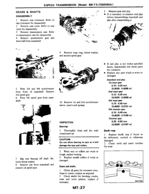
11 Install front bearing retamer to
case
Be sure to position it so that
the
oll collector groove is up
@ : 15 - 27 Nm
(1.5 - 2.8 kg-m,
11-20h-lb)
12 Install 5th speed shift fork, 5th
speed counter gear and synchronuer as
a umt Ahgn
pm holes m duft fork
and
sluft rad and mstall retmmg pm
13 Install thrust race and snap rmg
to rear of 5th speed synchronuer hub
14 Install case cover Refer to case
cover for assembly
15 Install rear extension Refer to
rear extension for assembly
16 Push mput shaft to rear and
mount dial mdicator
so that its stem
rests aganst the front end of the
input shaft Zero indicator
17 Push output shaft forward and
read mdicator Record readmg for
calculation Remove mdicator
.-. ,
18 Remove beanng retamer and bear-
ing race Select proper thckness
sium
to provlde 0 13 to 025 mm (00051
to 0 0098 m) preload
Calculation Example
A
+ B = Shim size
(A) Indicator reading 0.10 rnm
(B) Desired preload 0.20 mm
Additional shim 0.30 mm
required
(deaance)
19 Apply a contmuous bead of
sealant
to bearing retamer matmg
surface and threads of bolts.
20 Install shuns and bearmg race
mto beanng retamer and lnstall the
beanng retainer as in Step 11
MT-26
Page 27 of 34
I
GEARS & SHAFTS
DISASSEMBLY
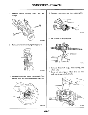
1 Remove rear extension Refer to
rear extension for disassembly
2 Remove case cover Refer to case
cover for disasse")
5SPEED TRANSMISSION [Model: BW T-5 (FS5R90A)I
GEARS & SHAFTS
DISASSEMBLY
1 Remove rear extension Refer to
rear extension for disassembly
2 Remove case cover Refer to case
cover for disassembly
3 Remove transmission case Refer
to transmission case for dsassembly
4 Remove speedometer gear and
drive ball from manshaft
.b ., . W"
5 Press 3rd and 4th synchronrzer
from front of mmshaft Remove
3rd speed gear
6 Press 5th speed gear from mam-
shaft
7 Shp rear beanng off shaft Re-
move thrust washer
8 Remove pm from mmshaft and
remove 1st speed gear
9
and second speed gear
Remove snap rmg, thrust washer,
10 Remove 1st and 2nd !,ynchronrzer
sleeve, inserts and spnngs
INSPECTION
Bearings
1
compressed au
CAUTION:
Do not allow bearing to spin as It will
damage the race and rollers.
Thoroughly clean and dry with
2
rough, replace bearing
3
damaged
Gean and shafts
1 Check all gears for excessive wear,
chips
or cracks, replace as requlred
2 Check shafts for bendmg, cracks,
wear and worn sphes, replace if
necessary
When race or rollers are worn or
Replace needle rollers if worn
or
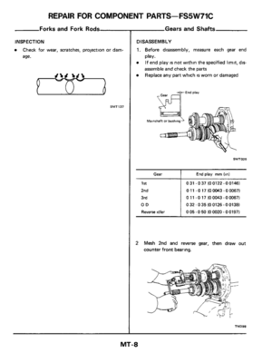
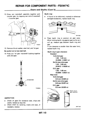
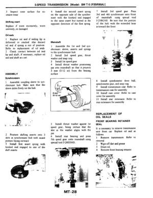
3 Measure gear end play
rn It is necessary to measure end play
before disassembhng mmshaft and
also after reassembhg it
rn If end play is not withm specified
hits, disassemble and check parts
for condition
rn Replace any part whch is worn or
damaged
Standard end play
1st main gear
0.10.025 mm
(0.0039 - 0.0098 in)
0.10 - 025 mm
(0.0039
- 0.0098 in)
0.15 - 0.40 my
(0.0059 .0.0157
in)
0.10 .0.48 mm
(0.0039.0 0189
in)
025.050 mm
(0.0098
- 0.0197 in)
2nd main gear
3rd main gear
5th counter gear
Counter gear
bulk rings
1 Replace baulk nng if found to
be deformed, cracked or otherwise
damaged
2 Check teeth and msert notches
for wear
SMT026
MT-27
Page 28 of 34
I
3 Inspect cone surface for ex-
cessive wear
Shifting insert
Replace if worn excessively, worn
unevenly, or damaged
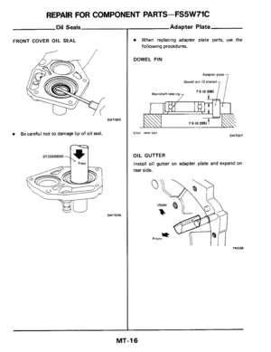
011 seals
1 Replace oll se")
5SPEED TRANSMISSION [Model: BW T-5 (FS5R90A)I
3 Inspect cone surface for ex-
cessive wear
Shifting insert
Replace if worn excessively, worn
unevenly, or damaged
011 seals
1 Replace oll seal if seahng hp is
deformed or cracked Also discard
OII seal d spnng is out of position
Refer
to replacement of OII seals
2 Check contact between
od seal
lip and shaft, if necessary, replace
oil
seal and shaft as a set
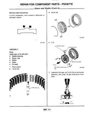
ASSEMBLY
Synchronizers
1 Assemble couplmg sleeve to syn-
chronuer hub Make sure that the
sleeve &des freely on the hub
2 Posltion duftmg mserts mto 3
slots m synchroruzer hub with raised
portion facmg outward
3 hstd first msert SpMg wlth
hooked end engaged
to one of the
shft mserts
4 Install the second insert sprlng
on the opposlte side of the synchro-
nuer with the hooked end engaged
to the same msert but turned in the
opposite direction of the first sprmg
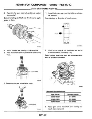
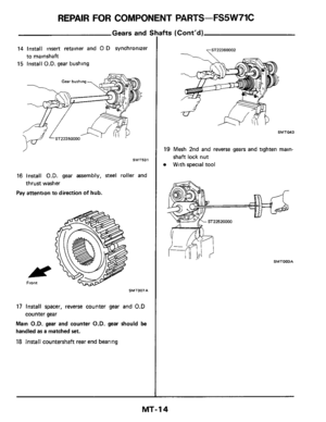
7 Install 3rd speed gear Press
3rd and
4th synchronuer onto front
of mainshaft using special
tool
J-25863-01 Be sure that the portion
of the hub with the extended hose
is toward the front
Mainshaft
1 Assemble the 1st and 2nd syn-
chronizer sleeve, mserts and springs
to the synchronuer hub
2 Install 2nd speed gear, thrust
washer and snap rmg
3 Install 1st speed gear
4 Install thrust washer positioning
pm into mmshaft
so that it projects
3 nun (0 12 in) from the bearmg
surface
5 Install thrust washer against 1st
speed gear, bemg certain that the
slot m the washer allgns mth the
Pm 6 Install rear beanng and press
5th speed gear onto mamshaft
usmg
special tool J-2.601041.
8 Install speedometer drive ball,
speedometer gear, and snap ring
9 Install transmission case Refer to
transmission case for assembly
10 Install case cover Refer to case
cover for assembly
11 Install rear extension Refer to
rear extension for assembly
REPLACEMENT OF
OIL SEALS
FRONT BEARING RETAINER
SEAL
It is necessary to remove transmission
unit from car Replace
all seal as
follows 1 Remove transmission Refer
to
removal
2
3 Dramall.
4 Remove front bearmg retamer
Wipe off dnt and grease
MT-28
Page 29 of 34
l
5 Remove oil seal
6 Clean bearing retainer and case
mating surface
7 Check beanng retainer and matmg
surface for cracks, nicks, projections")
SSPEED TRANSMISSION [Model: BW T-5 (FS5R90A)l
5 Remove oil seal
6 Clean bearing retainer and case
mating surface
7 Check beanng retainer and matmg
surface for cracks, nicks, projections
or sealant
8 Apply a coat of transmission fluid
to oil seal surface and install seal usmg
seal installer J-23096
- -.
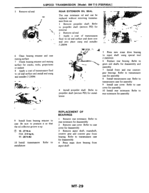
REAR EXTENSION OIL SEAL
The rear extension oll seal can be
replaced without removing transmis-
sion from car
1 Remove propeller shaft Refer
to propeller shaft (section
PD) for
removal
2 Remove oll seal
3 Apply a coat of transmission
fluid
to oil seal surface and drive new
seal into place
usmg seal installer
J-28894
4 Install propeller shaft Refer to
propeller shaft (section
PD) for instal-
lation
REPLACEMENT OF
BEARINGS
9 Install front bearing retainer to
case Be sure to position
it so that
the
oil collector groove is up
@ 15.27N.m
(1.5 - 2 8 kg-m,
11 -20ft-lbl
10 Install transmission Refer to
installation
1 Remove rear extension Refer to
rear extension for disassembly
2 Remove case cover Refer
to case
cover for disassembly
3 Remove mput shaft, mmshaft,
counter gear
and counter gear front
beanng Refer to tranmission case
for disassembly
4 Press man drive bearmg from
input shaft
5 Press new mam drive bearmg
to mput shaft usmg special tool
J-26010-01 6 Replace rear bearmg Refer
to
gears and shafts for disassembly and
assembly
7 Install front and rear counter-
gear bearmgs Refer to transmission
case for assembly
8 Install transmission case Refer to
transmission case for assembly
9 Install case cover Refer to case
cover for assembly
10 Install rear extension Refer to
rear extension for assembly
MT-29
Page 30 of 34
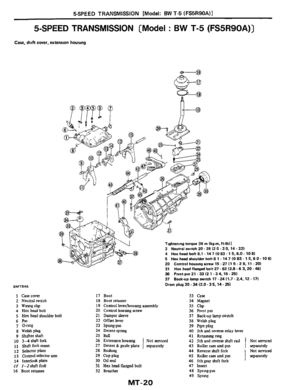
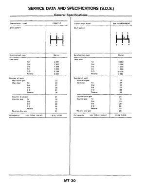
SERVICE DATA AND SPECIFICATIONS (S.D.S.)
Synchromesh type
General I
Warner
Transmtrrion -ode1
Shnft pattern
I
Synchromesh type
Gear ratio 1st
2nd
3rd
4th
OD
Re"e,Se
Number of teeth
Maln drive gear
Main bear 1st 2nd
3rd
OD
Reverse
Counter drive gear
counter gear 1st 2nd
3rd
OD RWeW
Reverse idler gear
011 capacity 1,ter (US pt Imp Pt)
FS5W71C
135
24R
Warner
3 321
1902
1308
1000
0 759
3 382
22
33
21 26
21
36
31 14
20
28 39
15
21
1 9 l4,3-3/81
cifications ~~
Slitft pattern
I ll 35
24R
Gear
ratio
1st 2nd
3rd
4th
OD
Reverse
3 350
2 056 1376
1 000
0 779
3
153
Number of teeth Main drive gear
Main gear 1 It
2nd
3rd
OD Reverse
23
34
32
21
29
32
Counter drwe gear Counter gear 1st
2nd
3rd OD
Reverse Reverse idler gear
34
15 23
29 55 15
20
011 capactty liter IUS pt. Imp ptl 1 1 9 I4 3-3/81
MT-30
Page 31 of 34
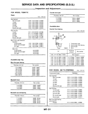
 ~
3
42 - 3 51 IO 1346 -0 13821
3 32.3 41 IO 1307.0 13431
322-331 101268-013031
3 12-321 101228-012641
3
02 - 3 11 10 1189 -0 12241
2 92.3 01")
SERVICE DATA AND SPECIFICATIONS (S. D. S.) ~
3
42 - 3 51 IO 1346 -0 13821
3 32.3 41 IO 1307.0 13431
322-331 101268-013031
3 12-321 101228-012641
3
02 - 3 11 10 1189 -0 12241
2 92.3 01 10 1150 -0 1185)
Inspection a ~ ~
0 1 IO 0041
32218. V5000
0 2 IO 0081 32218 - V5001
03(00121 32218-V5002
04IOO16l 32218-V5003
0 5 IO 0201 32218- VM04
0 6 IO 0241 32218 - V5005
FOR MODEL FS5W71C
Gears Unit mm linl
Gear backlash
Main drive gear
1st gear
2nd gear 3rd gear
0 D gear
Reverse
idler gear
0 05 - 0 10 IO 0020 - 0 00391 0 05.0 20 IO 0020 - 0 00791 0 05.0 20 IO 0020.0 00791
0 05.0 20 IO 0020 - 0 00791
0 05 - 0 20 (0 0020 - 0 00791
0 05 - 0 20 IO 0020 - 0 00791
Gear end play
1st gear 2nd gear
3rd gear 0 D gear
Reverse
idler gear
0 31 - 0 37 IO 0122.0 0146) 0 11 -0 17 (00043- 0 00671
0 11 .O 17 (0 0043.0 00671
032 - 0 35 10 0126 -0 01381
0 05 - 0 50 IO 0020.0 01971
Baulk ring to gear clearance
1st & 2nd gear 3rd & main drive gear
Standard
1 00 - 1 40 (0 0394.0 0551 I
1 20. 1 50 IO 0472.0 0591 I
0 D gear 1 00.1 40 IO 0394 -0 05511
Wear limtt
1st & 2nd gear
0 D gear
0 5 10 0201
0 5 IO 0201
3rd & main drive gear 0 8 (0 0311
Available snap ring
Main drive gear bearing
Thickness mm (In1 Part numbel
1 73 IO 0681 I 32204 - 78005
1
80 IO 07091 32204 78000 1 87 IO 07361 32204.78001
1 94 IO 07641 32204.78002
2 01 IO 07911 32204 - 78003
2 08 10 08191 32204 - 78004
Mainshaft front
Thickness mm (in1 Part number
1 4 IO 0551
1 5 IO 0591
1 6 IO 0631
32263. V5200
32263
- V5201
32263. V5202
Mainshaft rear end bearing
Thickness mmlinl Part number
1 1 (0 0431
1
2 IO 0471
1 3 IO 051 I
t 4 (0 0551
32228 20100 32228 - 20101
32228 20102
32228
- 20103
I Adjustment
Counter drive gear
-
Thickness mm Id Part number -
1 4 IO 0551
1 5 IO 0591
1 6 IO 0631
3221 5. E9000
32215- E9001
3221 5
- E9002 -
Available shim
Counter front bearing
Lht mm lml
1 Transmisrron care
2 Counter gear front bearlng
3 Counter gear
TM371 4 Shim
‘,A” Thickness Of shim Part number
352-371 101386-014611 1 Not necessary
FOR MODEL BW T-5 (FS5R90A) Unit mm (m)
Transmission model
Gear backlash
Main drive gear 0 05 - 0 15 IO 0020.0 00591
1st
gear 0 05.0 15 IO 0020 0 00591
2nd
gear 0 05 - 0 15 IO 0020 0 00591
3rd
gear 0 05 - 0 15 IO 0020.0 w591
5th gear 0 05 - 0 15 IO 0020 -0 00591
Reverse idler gear 0 10 - 0 20 IO 0039.0 00791 -
Gear end play
1st main gear 0 10 - 0 25 IO 0039.0 00981
2nd main gear 0 10 - 0 25 10 0039.0 00981
3rd
main gear 0 15 - 0 40 10 0059 - 00157)
5th counter
gear 0 10-048100059-001891
0 25 -0 50 IO 0098 -00197l counter gear - Main drive gear bearing
adjusting
shim
Preload 0 13 - 0 25 10 0051 - 0 00981 -
-
MT-31
Page 32 of 34

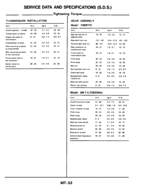
Clutch operatin- vlinder 30 40 3 1 .4 1 22 - 30
Tranrmirsian to engine 43. 58 4 4 - 5 9 32 - 43
Engm rear plate to 9-12 09-12 65-87
tranimlwon
Crossmem")
SERVICE DATA AND SPECIFICATIONS (S.D.S.)
Clutch operatin- vlinder 30 40 3 1 .4 1 22 - 30
Tranrmirsian to engine 43. 58 4 4 - 5 9 32 - 43
Engm rear plate to 9-12 09-12 65-87
tranimlwon
Crossmember
to body 31-42 32-43 23-31
Rear mounting insulator 31 - 42 3 2 - 4 3 23 - 31
to crossmember
Rear mounting insulator
31 -42 3 2 - 4 3 23 - 31
to rear exterlslo"
Transmission case IO 16-21 16-21 12-15
rear extenslo"
Starter motor to 29-39 30-40 22-29
tranmission
Tightenin!
I
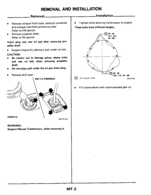
TFiANSMlSSlON INSTALLATION
Unit Nm kg-m ft-lb
I
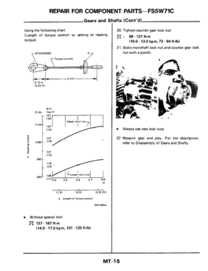
g Torque
GEAR ASSEMBLY
Mode'. FS5W71C
U"lt Nm kg-m ft-lb ~~
Bearing retamer IO 16-23
16-23 12-17 adapter plate
Mainshaft
lock nut 137-167 140-170 101.123
Counter gear lock nut 98-127 100-130 72-94
Rear extension to 16.21 16-21 12-15 transmission case
Front cover to 16-21 16-21 12-15 transmission case
Filler plug 25 - 34 25-35 18-25
Drain plug 25-34 25-35 18-25
Ball PI" 20.34 20-35 14-25
Strtkmg lever lock nut 9- 12 09-12 65-87
Check ball plug 19-25 19-25 14-18
Speedometer sleeve 4-5 04-05 29-36 installation
Backap lamp switch
20-29 20-30 14-22
Return rprlng plug 8- 10 08-10 58-72
Model: BW T-5 (FS5R90A)
U"lt Nm kg-m ft-lb
Clutch housing to case
Cover
to case
Front retainer to case
Filler plug
Drain plug
Speedometer sleeve
Back-up lamp swtch
Reverse PfYDt pm
Neutral witch
Extension to care
Control lever housmg to
extenson
41 -69
81-147 15-27
20.34
20.34
4-5 17-24
21 -33
20.29
27
- 62
15-27
42-70
083-15 15-28
20-35
20-35
04-05
17-24
21-34
20-30
28-63
15-28 30 - 51
60-108 11 -20
14-25
14
- 25
29-36
12-17
16
- 25
14
- 22
20 .46
11
-20
MT-32


Synchromesh type
General I
Warner
Transmtrrion -ode1
Shnft pattern
I
Synchromesh type
Gear ratio 1st
2nd
3rd
4th
OD
Re\"e,Se
Number of teeth
Ma")