Page 9 of 34
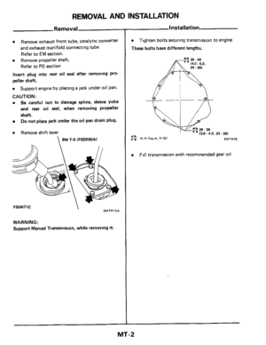
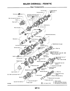
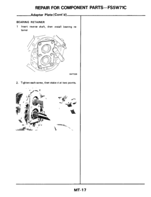
REPAIR FOR COMPONENT PARTS-FS5W71C
Gears and S
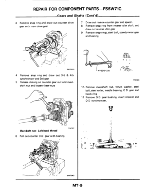
3 Remove snap ring and draw out counter drive
gear with main drive gear
SMT023
4 Remove snap ring and draw out 3rd & 4th
synchronizer and 3rd
gear
5 Release staking on counter gear nut and main-
shaft nut and loosen these nuts
TM757
Mainshaft nut: Left-hand thread
Pull out counter 0.D gear with bearing 6
ifts (Cont'd)
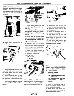
7
8
9
Draw out reverse counter gear and spacer.
Remove snap ring from reverse idler shaft, and
draw out reverse idler gear
Remove snap rings,
steel ball, speedometer gear
and bearing
-37 \ II \ .' I . .-
KV32101330
TM760
10. Remove mainshaft nut, thrust washer, steel
ball, steel roller, needle bearing, 0 D gear and
baulk ring
11 Remove 0 D gear bushing, insert retainer and
0 D synchronizer.
MT-9
Page 10 of 34

REPAIR FOR COMPONENT PARTS-FS5W71C
Gears and S
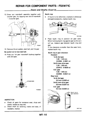
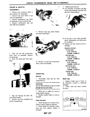
12. Draw out mainshaft assembly together with
counter gear, by tapping rear end of mainshaft
- d counter gear.
13 Remove thrust washer, steel ball, and 1st gear
Be careful not to lose steel ball.
14 Press out 1st gear mainshaft bushing together
with 2nd gear.
d H
TMMSA
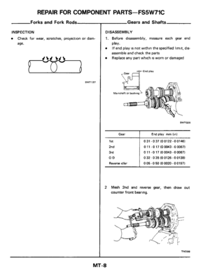
INSPECTION
0 Check all gears for excessive wear, chips and
cracks, replace
as required.
Check shaft for bending, cracks and wear, if
necessary, replace
0
ifts (Cont'd)
bulk rings
0 If found to be deformed, cracked or otherwise
damaged excessively, replace baulk ring
SMT026
0 Place baulk ring in position on gear cone
While holding baulk ring against gear
as far as it
will go, measure gap between baulk ring and
gear If the clearance
is smaller than the wear limit,
replace baulk ring.
Baulk ring to gear clearance:
Standard
1st & 2nd gear
1.00 - 1.40 mm
(0.0394 - 0 0551 in)
3rd & main drive gear
1.20 - 1.60 mm
(0.0472 - 0 0630 in)
1 .OO - 1.40 mm
(0.0394 - 0.0551 in)
O.D. gear
Wear limit
1st & 2nd gear
0.5 mm (0.020 in)
3rd
& main drive gear
0.8 mm (0.031 in)
O.D. gear
0.5
mm (0.020 in)
hulk ring to gear clearance
w SMT140
MT-10
Page 11 of 34
REPAIR FOR COMPONENT PARTS-FS5W71C
Gears and S
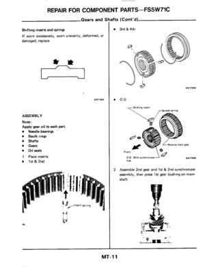
Shifting inserts and springs
If worn excessively, worn unevenly, deformed, or
damaged, replace
SMTO64
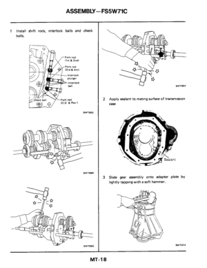
ASSEMBLY
Note:
Apply gear oil to each
part.
Needle bearings
Baulk rings
Shafts
Gears
Oil seals
1 Place inserts
1st & 2nd
ifts (Cont'd)
3rd &4th
OD
SMT994
0 D (5th) synchronizer SMT986 hub
2 Assemble 2nd gear and 1st & 2nd synchronizer
assembly, then press 1st gear bushing on main-
shaft
MT-11
Page 12 of 34
REPAIR FOR COMPONENT PARTS-FS5W71C
Parts number
Gears and 5
Thickness mm (in)
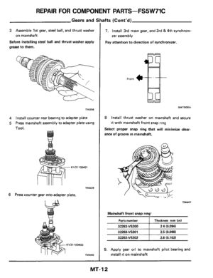
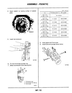
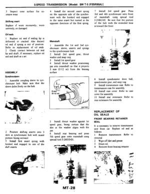
3 Assemble 1st gear, steel ball, and thrust washer
on mainshaft
Before
installing steel ball and thrust washer apply
grease
to them.
32263-V5202
TM358
4 Install counter rear bearing to adapter plate
5 Press mainshaft assembly to adapter plate using
Tool.
2.6 (0.102)
KV31100401
TM439
6 Press counter gear into adapter plate.
Bfts (Cont'd)
7. Install 3rd main gear, and 3rd & 4th synchroni-
zer assembly
Pay attention to direction of synchronizer. ~
Front
SMT008A
8 Install
thrust washer on mainshaft and secure
it with mainshaft front snap ring
Select proper snap ring that will minimize clear-
ance
of groove in mainshaft.
TMMl
Mainshaft front snap ring'
2.5 (0.098) 32263-V5201 I
9. Apply gear oil to mainshaft pilot bearing and
install it on mainshaft
MT-12
Page 13 of 34
REPAIR FOR COMPONENT PARTS-FS5W71C
Parts number -
Gears and S
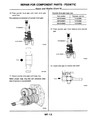
10 Press counter drive gear with main drive gear
Pay attention to direction of counter front gear.
using Tool. Thickness mm (in)
a
ST23860000
32215-€9000
KV31100401
1 4 (0 055)
TM442
32215-E9001
Front 4 t-- t
15 (0.059)
11 Secure counter drive gear with snap ring
Select proper snap ring that will minimize clear-
ance of groove in countershaft.
322 15-€9002
TM366
1.6 (0.063)
ifts (Cont'd)
12 Press counter gear front bearing onto counter
gear
-Ba
ST22360002
13. Install idler gear to reverse idler shaft
Front c
MT-13
Page 14 of 34
REPAIR FOR COMPONENT PARTS-FS5W71C
Gears and 5
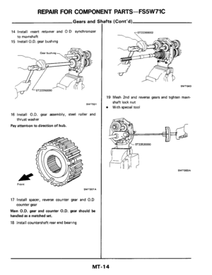
14 Install insert retainer and 0 D synchronizer
15 Install O.D. gear bushing
to mainshaft
,J
SMT531
16 Install O.D. gear assembly, steel roller and
Pay attention to direction
of hub.
thrust washer
SMT007A
17 Install spacer, reverse counter gear and 0.D
counter gear
Main
O.D. gear and counter O.D. gear should be
handled as a matched set.
18 Install countershaft rear end bearing
ifts (Cont'd)
SMTM3
19 Mesh 2nd and reverse gears and tighten main-
shaft lock nut
With special tool
SMT003A
MT- 14
Page 15 of 34
REPAIR FOR COMPONENT PARTS-FS5W71C
Gears and S
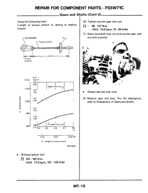
Using the following chart
(Length
of torque wrench vs. setting or reading
torque)
7 ST22520000 c7
I I1 5) 12 0) (2 5) Iff)
L Length of torque wrench
SMT004A
Without special tool
[91 137-167N.m
(14.0 - 17.0 kg-m, 101 - 123ft-lb)
3fts (Cont’d)
20 Tighten counter gear lock nut
: 98-127N.m
(10.0 - 13.0 kgm, 72 - 94 ft-lb)
2 I. Stake mainshaft lock nut and counter gear lock
nut with a punch.
22 Measure gear end play. For the description,
Always use new lock nuts
refer to Disassembly of Gears and Shafts.
MT-15
Page 16 of 34
REPAIR FOR COMPONENT PARTS-FS5W71C
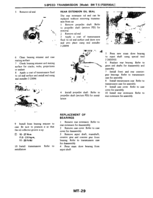
Oil Seals
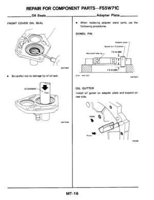
FRONT COVER OIL SEAL
Be careful not to damage lip of oil seal.
ST23800000
Adapter Plate
When replacing adapter plate parts, use the
following procedures.
DOWEL PIN
Adapter plate
oowel pm 12 placer)
7 5 IO 2951 1 Mainshaft bearing7
umt mrn I!") SMT027
OIL GUTTER
Install
oil gutter on adapter plate and expand on
rear side.
... TM356
MT-16


3 Assemble 1st gear, steel ball, and thrust washer
on mainshaft
Before
installing steel ball and thrust washe")


7 ST22520000 c7
I I1 5) 12 0) (2 5) Iff)
L Length of torque")
