Page 20 of 34
![NISSAN 300ZX 1984 Z31 Manual Transmission Workshop Manual 5-SPEED TRANSMISSION [Model: BW T-5 (FS5R90A)l
5-SPEED TRANSMISSION [Model : BW T-5 (FS5R90A)]
Case. shift cover, extension housing
Tightening torque [N m 1kg-m.ff-lbll
2 Neutral witch 20 - 29 1 NISSAN 300ZX 1984 Z31 Manual Transmission Workshop Manual 5-SPEED TRANSMISSION [Model: BW T-5 (FS5R90A)l
5-SPEED TRANSMISSION [Model : BW T-5 (FS5R90A)]
Case. shift cover, extension housing
Tightening torque [N m 1kg-m.ff-lbll
2 Neutral witch 20 - 29 1](/manual-img/5/575/w960_575-19.png)
5-SPEED TRANSMISSION [Model: BW T-5 (FS5R90A)l
5-SPEED TRANSMISSION [Model : BW T-5 (FS5R90A)]
Case. shift cover, extension housing
Tightening torque [N m 1kg-m.ff-lbll
2 Neutral witch 20 - 29 12 0.3 0, 14 - 221
4 Hex head bolt 8.1 - 14 7 10 83 - 1 5,6.0.10 81 5 Hex head shoulder bolt 8 1 - 14 7 IO 83.1 5.6 0 -
20 Control housing rrew 15 - 27 11 5 - 2 8.11 - 201
31 Hex head flanged bolt 27 - 62 12.8.6 3,20 .461
36 Pivot pin 21 -33 12 1 -34, 15-25)
37 Bad-up lamp
witch 17 - 24 11.7 .2.4.12.171
Drain plug 20 .34 (2.0.3 5, 14 - 251 SMT846
1 Casecwer
2 Neutralswltch
3 Wmgcbp 4 Hexheadbolt
5 Hex head shoulder bolt
6h 7 0-nng
8 Welshplug
9 Shfter shaft 10 3-4 Mtfork 11 swt fork msert
12 Selector plate 13 Control seiector ann
14 Interlock plate I5 I-Zshrft fork
16 Boot retamer
10 81
17 Boot 18 Boot retamer
19 Control Iever/housng assembly 20 Control houmg screw
21 Dampersleeve
22 Offset lever 23 Spmg-pm
24 Detentspmg
25 Ball
26 Extennon housmg Not sewiced 27 Detent & guide plate ! separately
28 Bushmg
29 Cup plug 30 01Iseal
31 Hex head flanged bolt
32 Breath
Mi-20
33 Case 34 Magnet 35 cllp 36 Plvatpm
37 Back-up lamp swtch
38 Welsh plug
39 Plpeplug 40 5th and reverse relay lever
42 5th and ~everse rhrft rad Not sernced
separately
Not se~ced
separately
41 Retammgmg
43 Roller cam and pm
44 Reverse duft fork
4$ Roller cam and pm
46 5th gear duft fork 47 Insert
48 Spring-pin 49 sprmg
!
Page 25 of 34

SSPEED TRANSMISSION [Model: BW T-5 (FS5R90A)I
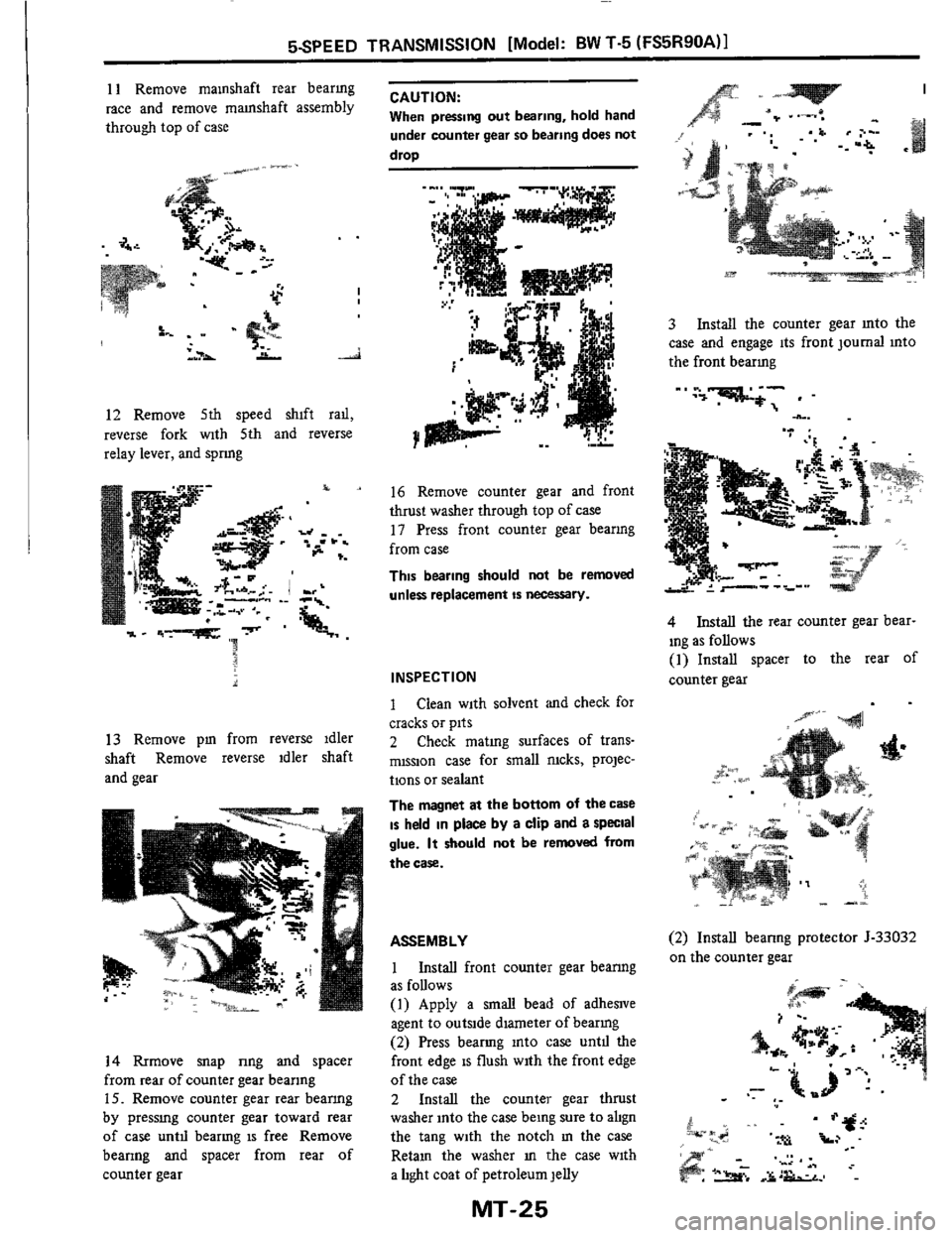
11 Remove mamshaft rear bearmg
race and remove mamshaft assembly
through top of case
I
12 Remove 5th speed shift rad,
reverse fork with 5th and reverse
relay lever, and spnng
13 Remove pm from reverse idler
shaft Remove reverse idler shaft
and gear
14 Rrmove snap nng and spacer
from rear of counter gear beanng
15. Remove counter gear rear beanng
by pressmg counter gear toward rear
of case untd bearmg is free Remove
bearing and spacer from rear of
counter gear
CAUTION:
When pressing out bearing, hold hand
under counter gear
so bearing does not
drop
16 Remove counter gear and front
thrust washer through top of case
11 Press front counter gear beanng
from case
This bearing should not be removed
unless replacement
is necessary.
INSPECTION
1 Clean with solvent and check for
cracks or pits
2 Check mating surfaces of trans-
mission case for small nicks, projec-
tions or sealant
The magnet at the bottom of the caSe
is held in place by a clip and a special
glue.
It should not be removed from
the case.
ASSEMBLY
1 Install front counter gear beanng
as follows
(1) Apply a
small bead of adheslve
agent to outside dlameter of bearmg
(2) Press bearmg into case untd the
front edge
is flush with the front edge
of the case
2 Install the counter gear thrust
washer into the case being sure
to abgn
the tang with the notch
m the case
Retam the washer
m the case with
a light coat of petroleum jelly
MT-25
3 Install the counter gear mto the
case and engage its front journal mto
the front bearmg
-' .".-:;-;' . -
.._. .." .
4 Install the rear counter gear bear-
ing as follows
(1) Install spacer to the rear of
counter gear
(2) Install beanng protector 5-33032
on the counter gear
Page 26 of 34

SSPEED TRANSMISSION [Model: BW T-5 (FS5R90A)I
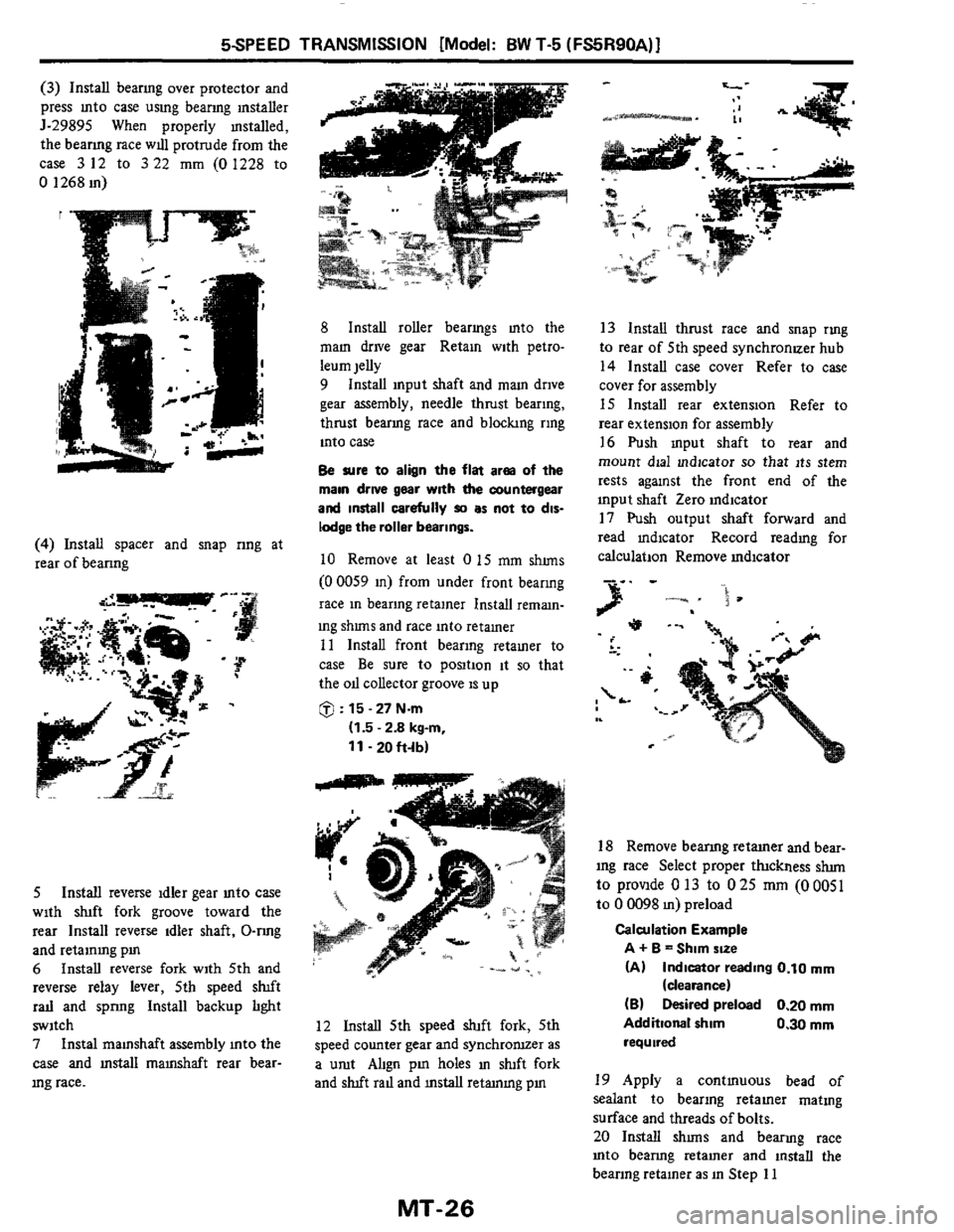
(3) Install beanng over protector and
press mto case uslng bearmg mstaller
J-29895 When properly mstalled,
the beanng race
WIU protrude from the
case
3 12 to 3 22 mm (0 1228 to
0 1268 in)
(4) Install spacer and snap nng at
rear of beanng
5 Install reverse idler gear mto case
with shft fork groove toward the
rear Install reverse idler shaft, 0-rmg
and retammg pm
6 Install reverse fork with 5th and
reverse relay lever, 5th speed sluft
rad and spnng Install backup hght
switch
7 Instal mamshaft assembly mto the
case and mstall mamshaft rear bear-
mg race.
8 Install roller bearmgs mto the
mam drive gear Retaxn with petro-
leum jelly
9 Install mput shaft and
mam drive
gear assembly, needle thrust bearing,
thrust bearmg race and bloclung ring
into case
Be sure to align the flat arm of the
main drwe gear wlth the countergear
and
install carefully IO as not to dis-
lodge the roller bearings.
10 Remove at least 0 15 mm shuns
(0 0059 in) from under front bearing
race
in bearing retainer Install reman-
ing
shuns and race into retainer
11 Install front bearing retamer to
case
Be sure to position it so that
the
oll collector groove is up
@ : 15 - 27 Nm
(1.5 - 2.8 kg-m,
11-20h-lb)
12 Install 5th speed shift fork, 5th
speed counter gear and synchronuer as
a umt Ahgn
pm holes m duft fork
and
sluft rad and mstall retmmg pm
13 Install thrust race and snap rmg
to rear of 5th speed synchronuer hub
14 Install case cover Refer to case
cover for assembly
15 Install rear extension Refer to
rear extension for assembly
16 Push mput shaft to rear and
mount dial mdicator
so that its stem
rests aganst the front end of the
input shaft Zero indicator
17 Push output shaft forward and
read mdicator Record readmg for
calculation Remove mdicator
.-. ,
18 Remove beanng retamer and bear-
ing race Select proper thckness
sium
to provlde 0 13 to 025 mm (00051
to 0 0098 m) preload
Calculation Example
A
+ B = Shim size
(A) Indicator reading 0.10 rnm
(B) Desired preload 0.20 mm
Additional shim 0.30 mm
required
(deaance)
19 Apply a contmuous bead of
sealant
to bearing retamer matmg
surface and threads of bolts.
20 Install shuns and bearmg race
mto beanng retamer and lnstall the
beanng retainer as in Step 11
MT-26