Page 9 of 38
DESCRIPTION-Air Conditioner (Manual)
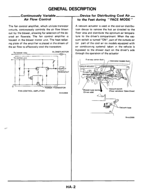
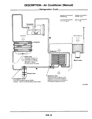
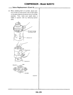
Refrigeration Cycle
Condenser
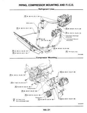
Safety valve Discharger refrigerant to
atmosphere at pressures above approx 3,727 kPa (38 kg/cm'. 540 psi) The valve cannot be reused -_ ..
Receiver drier
Delivers sprayed refrlgerant to the
evaporator to facilitate refrigerant
evaporation and controls the amount
of refrigerant passing the orifice
Turns OFF at pressures below 196 kPa (2 kglcm', 28 psi1 cutting compressor power supply
v
I
44
Blower motor
SHA238B
Page 10 of 38

Refrigerant Leak Warning System
The refrigerant leak warning system, used in con-
junction with the low-pressure switch, protects the
cooler cycle fro")
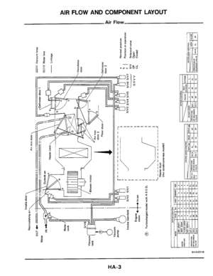
DESCRIPTION-Air Conditioner (Manual)
Refrigerant Leak Warning System
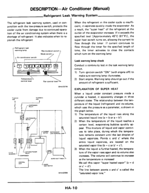
The refrigerant leak warning system, used in con-
junction with the low-pressure switch, protects the
cooler cycle from damage due to continued opera-
tion of the
air conditioning system when there is a
shortage of refrigerant
It also indicates when to re-
plenish the refrigerant
Refrigerant leak
warnmg lamp Recirculation switch
Air conditioner switch
control lever
SHA227B
I ll I
SHA2286
When the refrigerant in the cooler cycle is insuffi-
cient,
it vaporizes quickly inside the evaporator As
a result, the "super heat" of the refrigerant at the
outlet of the evaporator increases
If it exceeds the
specified level [Approximately 45°C
(8l0F)1, the
super heat switch turns on, allowing the current to
flow through the timer If current continues to
flow through the timer for the specified length of
time, the timer activates to close the contacts
which turn on the warning lamp
Leak warning lamp check
Conduct a continuity test in the leak warning lamp
circuit.
1) Turn ignition switch "ON" (with engine off) to
make sure warning lamp illuminates.
2) Start engine. Warning lamp should go out if the
amount of refrigerant
is sufficient.
EXPLANATION OF SUPER HEAT
When a liquid under constant pressure inside a
cylinder is heated, it apparently changes in three
different
states The relationship between the tem-
perature of the liquid (refrigerant) and
its volume,
which
uses the pressure as a parameter, is shown in
the graph below.
1) The temperature of the liquid rises along the
saturated liquid line (a -+ b or a + b')
2) When the temperature of the liquid reaches a
certain level, evaporating bubbles quickly ap-
pear This mixture of liquid and vapor contin-
ues to take place, during which the tempera-
ture remains constant until the
last droplet of
liquid vaporizes. Points c and c' where the
entire liquid vaporizes, are located on the
saturated vapor line (b
+ c or b -+ c').
3) When the liquid is further heated, the tempera-
ture of the vapor
rises again and its volume also
increases.
The volume will continue to increase
as the temperature is increased
We call this vapor "super heated vapor" (c + d
or c'
+ d')
The line between points c and c'
is called the
"saturated vapor line."
HA-I 0
Page 11 of 38

Refrigerant Leak Wai
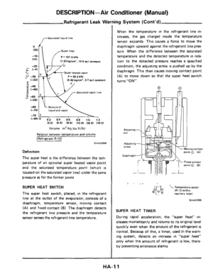
,---Saturated liquid line
Super heat
-10 P=1010kPa
I1 03 kg/cm2, 14 6 si1 mnsant (141
U 4- Super heated vapor
P = 39 2 kPa 10 40 kgl")
DESCRIPTION-Air Conditioner (Manual)
Refrigerant Leak Wai
,---Saturated liquid line
Super heat
-10 P=1010kPa
I1 03 kg/cm2, 14 6 si1 mnsant (141
U 4- Super heated vapor
P = 39 2 kPa 10 40 kglcm', 5 7 pal mmtant (-221
2 -40
P Saturated vapor line
5 40 + (-581
40 1, k;xture; 1 , (-761 liquid and vapor
-70
(-9410 02 04 06 08 10 12 1321 (641 (9 61 (12 81 (16 01 (1921
Volume m3/kg (cu ftilb)
Relation between temperature and volume
(Refrigerant R-121
SHA2398
Definition
The super heat is the difference between the tem-
perature of an optional super heated vapor point
and the saturated temperature point (which
is
located on the saturated vapor line) under the same
pressure
as for the former point
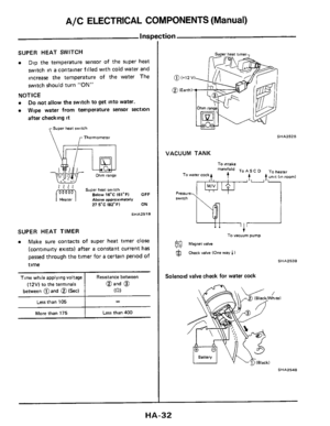
SUPER HEAT SWITCH
The super heat switch, placed, in the refrigerant
line
at the outlet of the evaporator, consists of a
diaphragm. temperature sensor, moving contact
(A) and fixed contact (B) The diaphragm detects
the refrigerant line pressure and the temperature
sensor senses the refrigerant line temperature.
ing System (Cont'd)
When the temperature in the refrigerant line in-
creases, the
gas charged inside the temperature
sensor expands This causes
a force to move the
diaphragm upward against
the refrigerant line pres-
sure When
the difference between the saturated
temperature and the detected temperature
in rela-
tion to the detected pressure reaches
a specified
condition, the adjusting screw
is pushed up by the
diaphragm This then causes moving contact point
(A) to move down so that the super heat switch
turns
"ON"
0
vmg COntaCt
I . ,I
$(& Temperature sensor & (R-12 within b~ capillary rubel
SHA2298
SUPER HEAT TIMER
During rapid acceleration, the "super heat" in-
creases momentarily and returns to
its original level
quickly even when the amount of the refrigerant
is
normal. Because of this, a timer, used in the warn-
ing system, detects an increase
in "super heat"
only when the amount of refrigerant
is low, there-
by preventing erroneous alarms
HA-I 1
Page 12 of 38

DISCHARGING, EVACUATING, CHARGING AND CHECKING
Precautions
WARNING:
Always be careful that refrigerant does not
come in contact with your skin.
Always wear
eye protection when working
around the
system
Keep refrigerant containers stored below 50°C
(122" F) and never drop it from a high place
Work
in well-ventilated area because refrigerant
gas evaporates quickly and breathing may be-
come difficult due to the lack of oxygen
Keep refrigerant away from open flames
be-
cause poisonous gas will be produced if it is
burns.
Do not use steam to clean surface of condenser
or evaporator
Be sure to use cold water or
compressed air.
Compressed
air must never be used to clean a
dirty line Clean with refrigerant gas
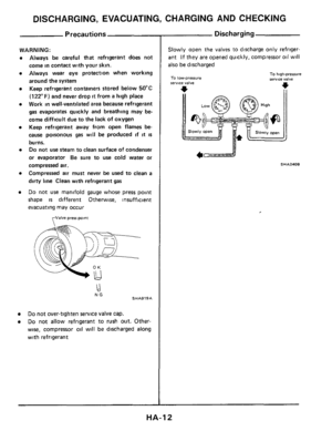
Do not use manifold gauge whose press point
shape
is different Otherwise, insufficient
evacuating may occur
fJalve press point
NG SHA919A
Do not over-tighten service valve cap.
Do not allow refrigerant to rush out. Other-
wise, compressor oil will
be discharged along
with refrigerant
Discharging
Slowly open the valves to discharge only refriger-
ant If they
are opened quickly, compressor oil will
also be discharged
To low-pressure IerYlCe valve
To high-pressure service valve
*
SHA240B
4c==--J
HA-I 2
Page 13 of 38

300 /1,000)
Evacuating The System
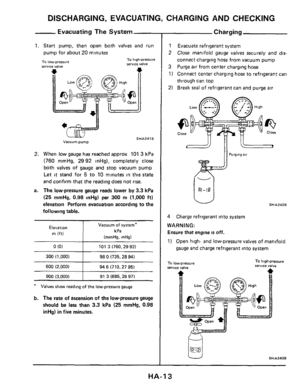
1. Start pump, then open both valves and run
pump for about 20 minutes
-. -
101 3 (760.29 92)
98")
DISCHARGING, EVACUATING, CHARGING AND CHECKING
0 (0)
300 /1,000)
Evacuating The System
1. Start pump, then open both valves and run
pump for about 20 minutes
-. -
101 3 (760.29 92)
98
0 (735.28 94)
To high-pressure serwce valve To low-pressure
600 (2,000)
Vacuum pump
94 6 (710.27 95)
SHA241 B
900 (3.000)
2. When low gauge has reached approx 101 3 kPa
(760 mmHg, 2992 inHg), completely close
both valves of gauge and stop vacuum pump
Let
it stand for 5 to 10 minutes in this state
and confirm that the reading does not rise.
a. The low-pressure gauge reads lower by 3.3 kPa
(25 mrnHg, 0.98 inHg) per 300 rn (1.000 ft)
elevation Perform evacuation according to the
following table.
91 3 (685.26 97)
I
Vacuum of system*
kPa
(mmHs. inHal
Elevation
m (ftl
* Values show reading of the low-pressure gauge
b. The rate of ascension of the low-pressure gauge
should be less than
3.3 kPa (25 mmHg, 0.98
inHg) in five minutes.
- Charging
1 Evacuate refrigerant system
2
Close manifold gauge valves securely and dis-
connect charging hose from vacuum pump
3 Purge air from center charging hose
1) Connect center charging hose to refrigerant can
through can top
2) Break
seal of refrigerant can and purge air
SHA2428
4 Charge refrigerant into system
WARNING:
Ensure that engine is off.
1) Open high- and low-pressure valves of manifold
gauge and charge refrigerant into system
SHA243B
HA-I 3
Page 14 of 38
 Quick charging
Immerse in water heated to about40*C 11W0FI for a Short time
AC184A
CAUTION.
If charging liquefied refrigerant into")
DISCHARGING, EVACUATING, CHARGING AND CHECKING
Chargin!
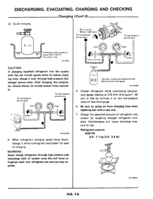
2) Quick charging
Immerse in water heated to about40*C 11W0FI for a Short time
AC184A
CAUTION.
If charging liquefied refrigerant into the system
with the can turned upside down to reduce charg-
ing time, charge it only through high pressure (dis-
charge) service valve. After charging, the compres-
sor should always be turned several times manual-
ly.
To high-pressure sermce valve To low-pressure
SHA244B
5. When refrigerant charging speed slows down,
charge
it while running the compressor for ease
of charging
WARNING:
Never charge refrigerant through high pressure side
(discharge
side) of system since this w~ll force re-
frigerant back into refrigerant can and can may
ex-
plode.
Cont'd)
Run at Idling (Below 1.500 rpml
To high-pressure servlce valve
II
To low-pressure IerUlCe valve
@g Fan lever, made and temperature dial Maximum cool and speed
I? SHAZ~SB
Charge refrigerant while controlling low-pres
sure gauge reading
at 275 kPa (2 8 kg/cm2, 40
psi) or less by turning in or out low-pressure
valve of manifold gauge.
Be sure to purge air from charging hose when
replacing can with a new one.
Charge the specified amount of refrigerant into
system by weighing charged refrigerant with
scale Overcharging will cause discharge pres-
sure
to rise.
Refrigerant amount:
MJS170
0.9 - 1.1 kg (2.0 - 2.4 Ib)
SHA9OOA
HA-I 4
Page 15 of 38
DISCHARGING, EVACUATING, CHARGING AND CHECKING
Charging (Cont'd)
The state of the bubbles in sight glass should only
be used for checking whether the amount of
charged refrigerant is small or not The amount of
charged refrigerant can be correctly judged by
means of discharge pressure.
8 After charging, be sure to install valve cap on
service valve
9 Confirm that there are no leaks in system by
checking with a leak detector
HA-I 5
Page 16 of 38

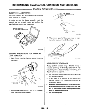
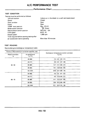
DISCHARGING, EVACUATING, CHARGING AND CHECKING
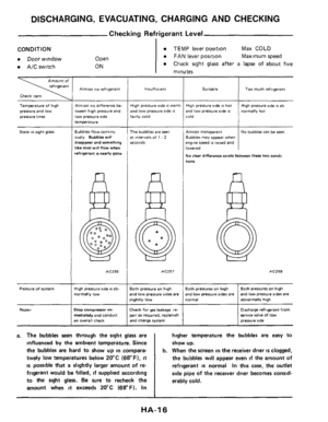
Checking Refrigerant Level
I
Suitable
CONDITION
Door window
AIC switch
TOO much refrigerant
Open
ON
TEMP lever position Max COLD
FAN lever position Maximum speed
Check sight glass after a lapse of about five
minutes
Check item
Terneralure of high
pressure and
low
pressure lines
Staie !n slght glass
Pressure of system
Repair
Almost no refrigerant
Almost no difference be-
tween high pressure and
low pressure side temperature
Bubbles flow continu
ously Bubbler will disappear and something
like mest will flow when
refrigerant
IS nearly gone
AC256
High Pressure side os ab-
normally low
Stop compressor m.
mediately and conduct an Overall check
iigh pressure side IS warm
Ind low pressure side is
awly cold
-he bubbler are seen
it inieivals of 1 - 2
econds
ACZ57
loth pressure on high
nd low pressure sides are
lighfly low
:heck for gas leakage re-
air as required. replenish Nnd charge system
a. The bubbles seen through the sight glass are
influenced by the ambient temperature. Since
the
bubbles are hard to show up in compara-
tively
low temperatures below 20°C (68°F). it
is possible that a slightly larger amount of re-
frigerant would be filled,
if supplied according
to the sight glass.
Be sure to recheck the
amount when
it exceeds 20°C (68°F). In
iigh pressure ride is hot
ind
low pressure ride 8s
High pressure Side IS ab
normally hot
4Imost transparent
lubblei may appear when ,ngine speed 8s raised and
owered
do dear difference exists between these two condi-
No bubbler can be seen
10"s
AC258
:oth pressures on high
nd
low pressure rides are ormal abnormally hgh
Both pressures on high
and
low pressure rider are
Dmharge refragerant from sewice valve of low
pressure ride
higher temperature the bubbles are easy to
show up.
b. When the screen in the receiver drier is clogged,
the bubbles will appear
even if the amount of
refrigerant
IS normal In this case, the outlet
side pipe of the receiver drier becomes consid-
erably cold.
1
HA-I 6

Refrigeration Cycle
Condenser
Safety valve Discharger refrigerant to
atmosphere at pressures above approx 3,727 kPa (38 kg/cm. 540 psi) The valve cannot be")

The state of the bubbles in sight glass should only
be used for checking whether the amount of
charged refrigerant is small or")