Page 17 of 38

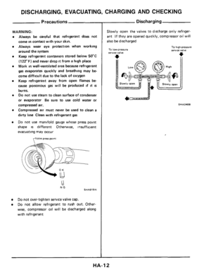
DISCHARGING, EVACUATING, CHARGING AND CHECKING
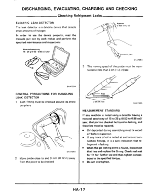
ELECTRIC L EAK-DETECTOR
The leak detector IS a delicate device that detects
small amounts of halogen
In order to
use the device properly, read the
manuals
put out by each maker and perform the
specified maintenance and inspections
Nominal senmivity 15.25 g (0 53.0 88 ozllvear
.. SHA733A
GENERAL PRECAUTIONS FOR HANDLING
LEAK DETECTOR
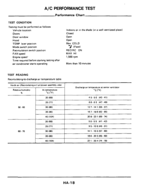
1 Each fitting must be checked around its entire
periphery
SHA734A
2 Move probe close to and 3 mm (0 12 in) away
from the point to be checked
SHA735A
3 The moving speed of the probe must be main-
tained
at less than 3 cm (1 2 in)/sec
SHA736A 3 cm (1 2 ml
MEASUREMENT STANDARD
If any reaction is noted using a detector having a
nominal sensitivity of 15 to 25 g (0.53 to 0.88 od/
year, that portion checked be found as leaking, and
therefore must be repaired.
Oil deposited during assembling musr be wiped
off before inspection
If any trace of oil is noted at and around con-
nection fittings,
it is a sure indication that re-
frigerant
is leaking
When the
gas leaking point is found, disconnect
that line and replace
the O-ring. Check seal seat
for fit for further use and then tighten connec-
tions
to the specified torque.
Do not overtighten.
HA-I 7
Page 18 of 38
A/C PERFORMANCE TEST
Performance Chart
Inside air (Recirculating air) at blower assembly inlet
Relative humidity At temperature
% OC (OF)
20 (68)
TEST CONDITION
Testing must be performed as follows
Vehicle location
Doors
Door window
Hood
TEMP lever position
Mode switch position
Recirculation switch position
FAN speed
Engine speed'
Time required before starting
testing after
air conditioner starts operating
Discharge air temperature at center ventilator
'C (OF)
45-50 (40-41)
TEST READING
Recirculating-to-discharge air temperature table
50-60
Indoors or in the shade (in a well ventilated place)
Closed
Open
Open Max
COLD
# (Face)
RECIRC ON
MAX HI
1,500 rpm
More than 10 minutes
-.
86-95 (47-49)
12 7
- 14 1 (55 - 57)
16 7.186
(62 -65)
25 (77)
30 (86)
35 (951
60 - 70
50-55 (41-42)
9 5
- 10 5 (49 - 51)
14
1 - 15 5 (57- 60)
18 6 - 20 5 (65 - 69)
20 (68)
25 (77)
30
(86)
35 (95)
208-231 (69-74)
40 (104) 231 -254174-78)
HA-I 8
Page 19 of 38

20 (68)
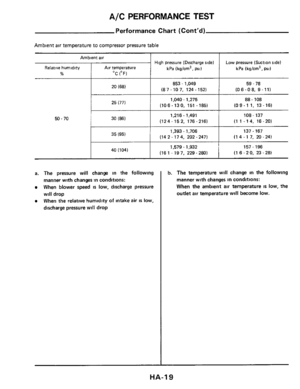
Performance Chart (Cont’d)
High pressure (Discharge side)
kPa (kg/cm2,
psi)
Low pressure (Suction si")
A/C PERFORMANCE TEST
Ambient air
Relative humidity Air temperature
% OC (OF)
20 (68)
Performance Chart (Cont’d)
High pressure (Discharge side)
kPa (kg/cm2,
psi)
Low pressure (Suction side)
kPa (kg/cm’, psi)
853 - 1,049 59 - 78
(87-107. 124-1521 (06-08. 9-11)
Ambient air temperature to compressor pressure table
I I
1,040.1,275 88.108 ~
25(771
(10 6 - 13 0, 151 - 185) (09-1 1. 13-16)
50.70 I I
1,216- 1,491 108 - 137
(124-152, 176-216) (1 1 .14, 16.20) 1 30(86)
I I
1,393 - 1,706 137.167
(14 2 - 174, 202 - 247) (14-17. 20-24)
I I
1,579 - 1,932
(161 -197, 229-280) 157 - 196
(1
6 - 2 0, 23 - 28) I 40(104)
a. The pressure will change in the following
manner with changes in conditions:
When blower speed is low, discharge pressure
will drop
When the relative humidity of intake air IS low,
discharge pressure will drop
b. The temperature will change in the following
manner with changes
in conditions:
When the ambient air temperature
IS low, the
outlet air temperature will become low.
HA-I 9
Page 20 of 38

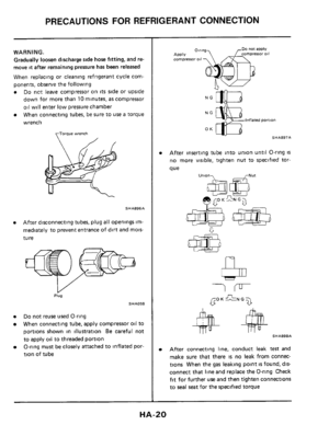
PRECAUTIONS FOR REFRIGERANT CONNECTION
WARNING.
Gradually loosen discharge side hose fitting, and re-
move
it after remaining pressure has been released
When replacing or cleaning refrigerant cycle com-
ponents, observe the following
Do not leave compressor on its side or upside
down for more than 10 minutes, as compressor
oil will enter low pressure chamber
When connecting tubes, be sure to
use a torque
wrench
torque wrench
SHA896A
After disconnecting tubes, plug all openings im-
mediately to prevent entrance of dirt and mois-
tu
re
Plug
SHA058
Do not reuse used O-ring
When connecting tube, apply compressor oil to
portions shown in illustration
Be careful not
to apply oil to threaded portion
O-ring must be closely attached to inflated por-
tion of tube
NG
lnflaied pomon
OK - SHA897A
After inserting tube into union until O-ring is
no more visible, tighten nut to specified tor-
que
u"'06a e GO K GN G 7
b
SHA898A
After connecting line, conduct leak test and
make sure that there
IS no leak from connec-
tions When the
gas leaking point IS found, dis-
connect that line and replace the O-ring Check
fit for further use and then tighten connections
to seal seat for the specified torque
HA-20
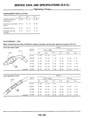
Page 21 of 38
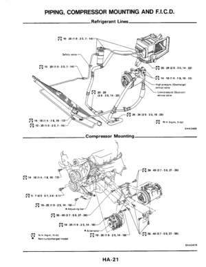
PIPING, COMPRESSOR MOUNTING AND F.I.C.D.
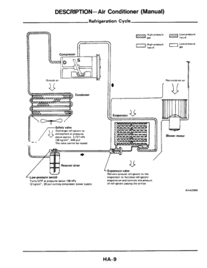
Refrigerant Lines
10 20110-20.7-14)
Safety valve
Lm 20- 29 (2 0 - 30.14 - 221
m 14 - 18 I1 4.1 8,lO - 131
20 - 29 Low-prerrure (S”Ctl0”)
fYm 1 (20 30.14- service valve
25 -34 (2 5 - 35,18 -251
m N m lkg-m, ft-lb)
SHA246B 0 10-20 I1 0-20.7. 14)J
Compressor Mounting
h
5-7(05 07.36-511i
[91 19-25 I1 9- 25.14.18)
*Adjurting bar
PJ) 36 -49 I3 7.5 0,27.361
(91 19 -25 (1 9.2 5,14.18)
N rn (kg-m, ft-lbl (91 19-2511
Non-turbocharged model
SHA247B
HA-21
>
36.49 I3 7.50.27 - 361 ,
9 - 25.14- 181
Page 22 of 38

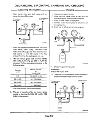
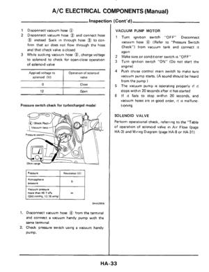
1
2
Run engine until it reaches operating tempera-
ture.
With air conditioning system
OFF (whe")
PIPING, COMPRESSOR MOUNTING AND F.I.C.D.
Idle Speed Adju
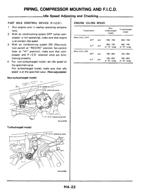
FAST IDLE CONTROL DEVICE (F.1.C.D )
1
2
Run engine until it reaches operating tempera-
ture.
With air conditioning system
OFF (when com-
pressor
is not operating), make sure that engine
is at correct idle speed
3 With air conditioning system ON (Recircula-
tion switch
at "RECIRC" position, fan control
lever
at "HI" position), make sure that com-
pressor and
F I C D solenoid valve are func-
tioning properly
For non-turbocharged model,
set idle speed at
the specified value
For turbocharged model, make sure that idle
speed is at the specified value (Nonadjustable)
4
Non-turbocharged model
F I C D socket pin 0
solenoid valve
Turbocharged model
solenoid valve
SHA248B
ng and Checking
ENGINE IDLING SPEED
NO"-
model
Turbocharged
model Tranrmission turbocharged
When AIC 86 OFF
MIT rpm 650-750 650 - 750
650.750 600.700 AIT rpm at "0" range at "D" range
When AIC IS ON
MIT rpm 750-850 750 - 850
750.850 750.850 AIT rpm at "D" range at "0" range
HA-22
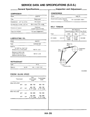
Page 23 of 38

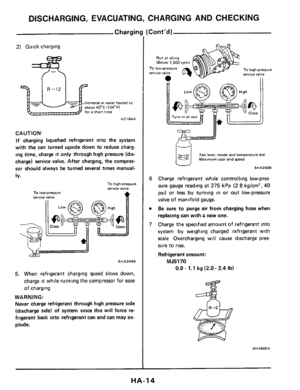
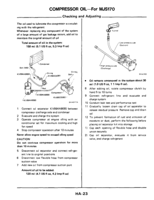
COMPRESSOR OIL--For MJS170
Checking and Adjusting
The oil used to lubricate the compressor is circulat-
ing with the refrigerant
Whenever replacing any component of the system
of
a large amount of gas leakage occurs, add oil to
maintain the original amount
of oil
Total amount of oil in the system:
150 mP (5.1 US fl 02, 5.3 Imp fl 02)
KV994A9690
KV992C50822 /
i;(V994A9690 SHAO17A
1
2
3
Connect oil separator KV994A9690 between
compressor discharge
side and condenser
Evacuate and charge the system
Operate compressor
at engine idling with air
conditioner
set for maximum cooling and high
fan speed
4 Stop compressor operation after 10 minutes
Never allow engine speed to exceed idling speed
CAUTION.
Do not continue compressor operation for more
than 10 minutes
5 Disconnect oil separator and connect refriger-
ant line
to original positions
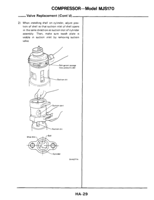
6 Disconnect low flexible hose from compressor
suction
valve
7 Add new oil from compressor suction port
Amount of oil to be added:
120 mP (4.1 US fl oz,4.2 Imp fl 02)
Low pressure ride
SHA702
0 Oil remains unremoved in the system about 30
mP (1.0 US fl 02, 1 1 Imp fl 02).
8 After adding oil, rotate compressor clutch by
hand 5 to 10 turns
9 Connect refrigerant line and evacuate and
charge system
10 Conduct leak
test and performance test
11 Gradually loosen drain cap of oil separator to
release residual pressure Remove cap and drain
Oil
12 To prevent formation of rust and intrusion of
moisture or dust, perform the following before
placing oil separator kit into storage
1) Cap each opening of flexible hose and double
union securely
2) Cap oil separator, evacuate it from service
valve, and charge refrigerant
HA-23
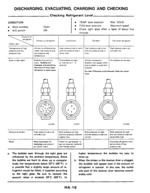
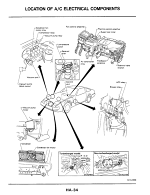
Page 24 of 38

Replacement of compressor
Replacement of evaporator
Replacement
of receiver drver (liquid tank)
There is")
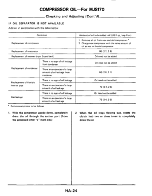
COMPRESSOR OIL-For MJS170
Condition Amount of oil to be added mP IUS fl 02. Imp fl 02)
Replacement of compressor
Replacement of evaporator
Replacement
of receiver drver (liquid tank)
There is no sign of oil leakage
from condenser
1 Remove all oil from new and old compressors *
2 Charge new compressor with the same amount of
oil as was in the old compressor
80 (2 7,2 8)
Oil need not be added
Oil need not be added
Replacement Of ‘Ondenser There are evidences of a large
amount of
oil leakage from
condenser 60 (2 0.2 1)
There is no sign of oil leakage
There are evidences of a large
amount of
oil leakage 70 (2 4, 2 5) hose or pipe
Oil need not be added
There is no sign of oil leakage
There are evidences
of a large
amount
of oil leakage
Gas leakage
* Remove compressor oil as follows
1. With the compressor upside down, completely
drain the
oil through the suction port (from
the embossed letter
“s” mark side)
Oil need not be added
70 I2 4, 2 5)
2 When the oil stops flowing out, rotate the
clutch hub
two or three times to completely
drain the
oil
HA-24
 at blower assembly inlet
Relative humidity At temperature
% OC (OF)
20 (68)
TEST CONDITION
Testing must be performed as")

Safety valve
Lm 20- 29 (2 0 - 30.14 - 221
m 14 - 18 I1 4.1 8,lO - 131
20 - 29 Low-prerrure (S”Ctl0”)
fYm 1 (")