Page 1 of 38
HEATER &
AIR CONDITIONER
I v __I_--
SECTION HA^ I
CONTENTS
GENERAL DESCR I PTlON . ... .. . HA- 2
AIR FLOW AND COMPONENT LAYOUT
. .. . .. HA- 3
DOOR CONTROL .. 1.. .. HA- 6
LOCATION OF VACUUM COMPONENTS ... HA- 5
HEATER ELECTRICAL CIRCUIT. . . . . .. HA- 7
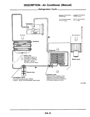
DESCRIPTION-Air Conditioner (Manual) . ... ..
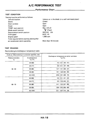
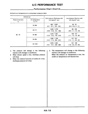
A/C PERFORMANCE TEST ..
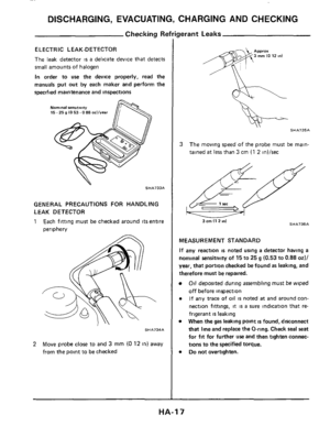
DISCHARGING, EVACUATING, CHARGING AND CHECKING
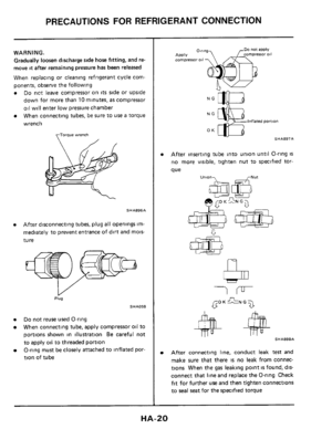
PRECAUTIONS FOR REFRIGERANT CONNECTION .
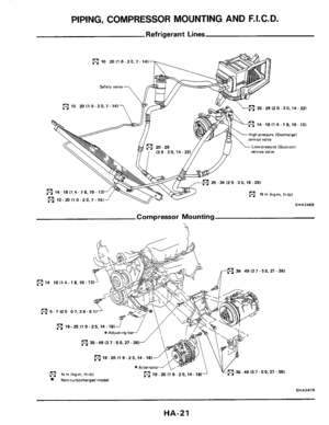
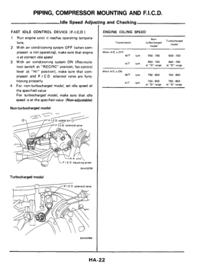
PIPING, COMPRESSOR MOUNTING AND F.1 C D.
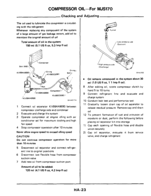
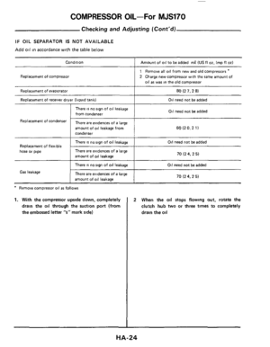
COMPRESSOR OIL-ForMJS170
. . .. ..
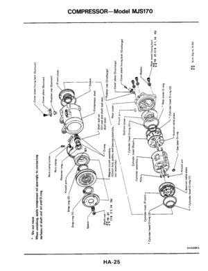
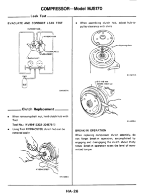
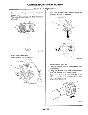
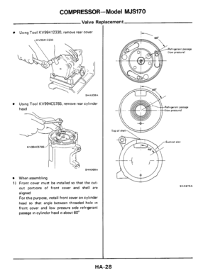
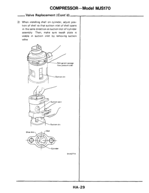
COMPRESSOR-Model MJS170 .. ..
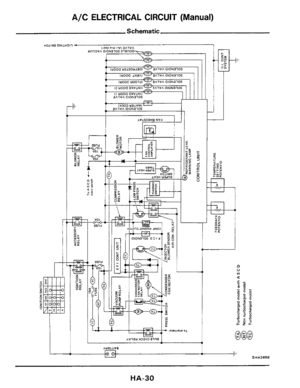
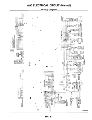
A/C ELECTRICAL CIRCUIT (Manual) . .. ..
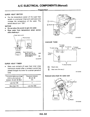
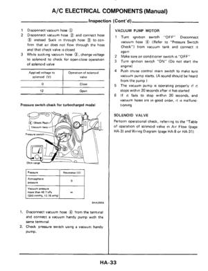
A/C ELECTRICAL COMPONENTS (Manual) ..
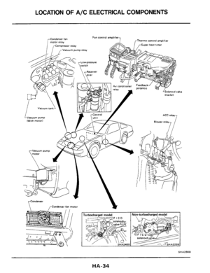
LOCATION OF A/C ELECTRICAL COMPONENTS ....
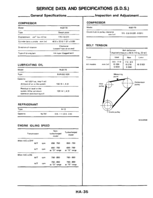
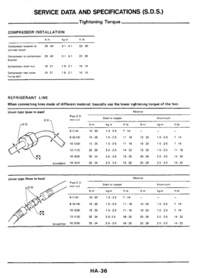
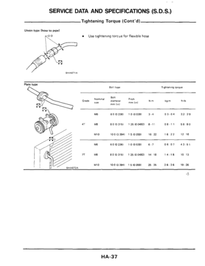
SERVICE DATA AND SPECIFICATIONS (S D S ) . .
SPECIAL SERVICE TOOLS .. ..
HA- 9
HA-12
HA-18
HA-20
. HA-21
HA-23
HA-25
. HA-30
.. HA-32
. HA-34
.. HA-35
. HA-38
Page 2 of 38

GENERAL DESCRIPTION
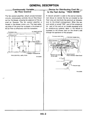
Continuously Variable Air Flow Control
The fan control amplifier, which utilizes transistor
circuits, continuously controls the air flow blown
out
by the blower, allowing for selection of the de-
sired air flowrate. The fan control amplifier
IS
housed in the blower motor unit. The heat-radiat-
ing plate of the amplifier
is placed in the stream of
the air flow to effectively cool the transistors
BLOWER MOTOR To blower relay M
AT AT
I - I __4;-..2 POWER TRANSISTOR
FAN CONTROL AMPLIFIER SHA255B
-Device for Distributing Cool Air -
to the Feet during " FACE MODE "
A vacuum actuator is used in the cool-air distribu-
tion device to remove the hot
air directed to the
floor area and distribute the optimum air tempera-
ture to the driver's compartment When the vac-
uum switch
is turned "ON", part of the outside air
(or part of the cool air on models equipped with
air conditioning systems) taken in the vehicle is
bypassed to the shower duct on the driver's side
through the operation of the actuator
4 Vacuum swfch IFloor ventilator Open-Close) 'Shower-ty pe nozzle (Driver sidel
Vacuum hose
a
HA-2
Page 3 of 38
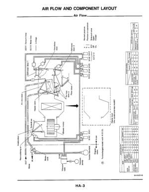
AIR FLOW AND COMPONENT LAYOUT
Air Flow
SHA231B
HA-3
Page 4 of 38
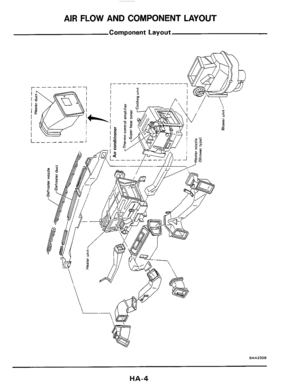
AIR FLOW AND COMPONENT LAYOUT
Component Layout
SHA232B
HA-4
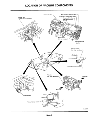
Page 5 of 38
LOCATION OF VACUUM COMPONENTS
\Vacuum tank
Vacuum pump motor
SHA2338
HA-5
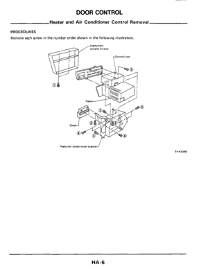
Page 6 of 38
DOOR CONTROL
Heater and Air Conditioner Control Removal
PROCEDURES
Remove each screw in the number order shown in the following illustration.
Radiolaw condnmner bracket f
SHA234B
HA-6
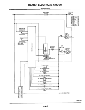
Page 7 of 38
HEATER ELECTRICAL CIRCUIT
Schematic
BATTERY
FEEDBACK
POTENT10
TEMPERATURE
SEmlNG POTENT10
I I
For water cock
FUSIBLE
LINK
1
4
BLOWER
RELAY
For intake actuator
For floor door actuator
For vemila~uator
Far defros-
DSVV IForawmtxdoor)
DSVV IForairmrxdoorl -
a
SHA236B
HA-7
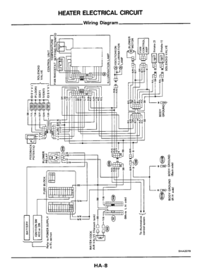
Page 8 of 38
HEATER ELECTRICAL CIRCUIT
Wiring Diagram
SHA237B
HA-8