Page 17 of 38

DISCHARGING, EVACUATING, CHARGING AND CHECKING
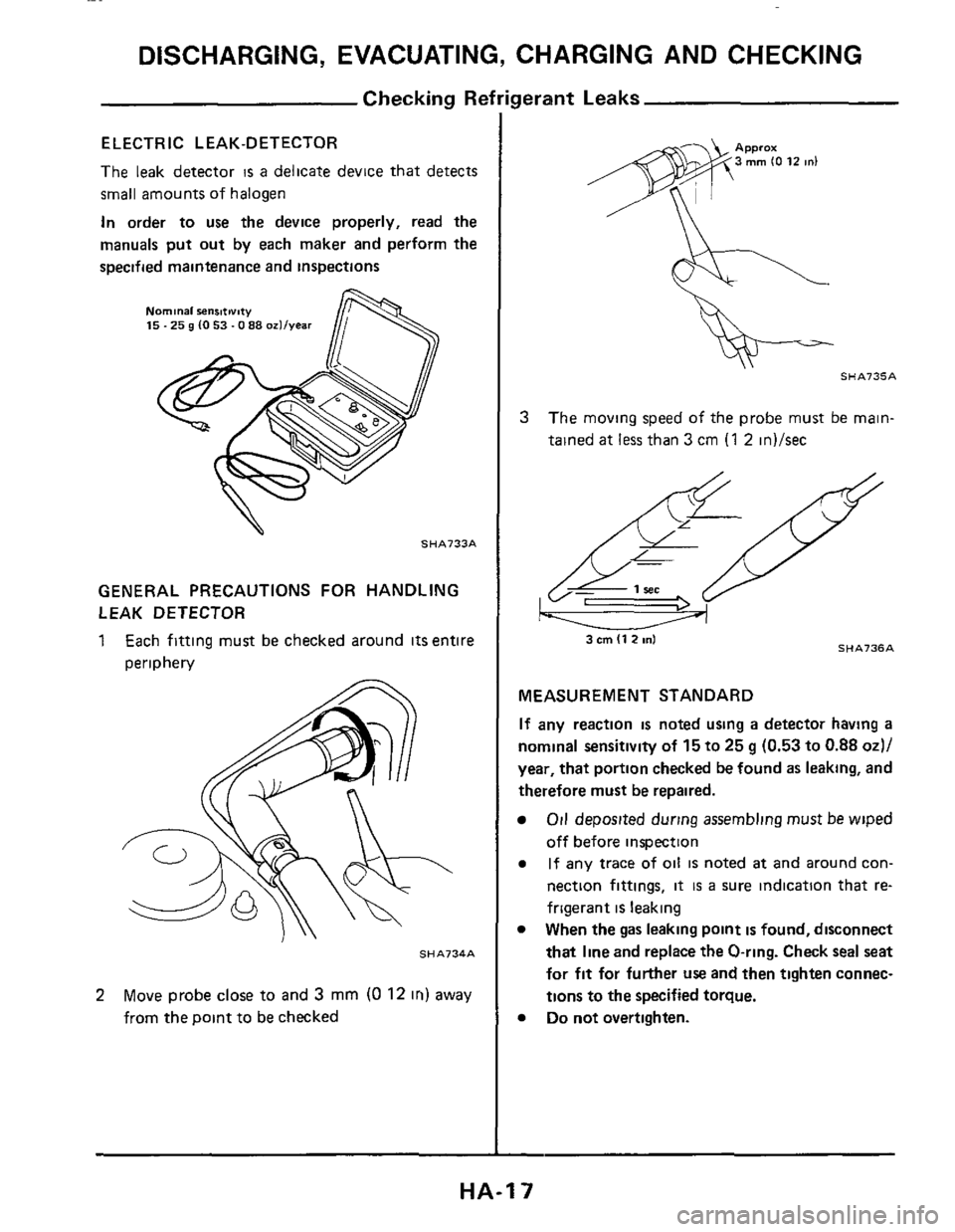
ELECTRIC L EAK-DETECTOR
The leak detector IS a delicate device that detects
small amounts of halogen
In order to
use the device properly, read the
manuals
put out by each maker and perform the
specified maintenance and inspections
Nominal senmivity 15.25 g (0 53.0 88 ozllvear
.. SHA733A
GENERAL PRECAUTIONS FOR HANDLING
LEAK DETECTOR
1 Each fitting must be checked around its entire
periphery
SHA734A
2 Move probe close to and 3 mm (0 12 in) away
from the point to be checked
SHA735A
3 The moving speed of the probe must be main-
tained
at less than 3 cm (1 2 in)/sec
SHA736A 3 cm (1 2 ml
MEASUREMENT STANDARD
If any reaction is noted using a detector having a
nominal sensitivity of 15 to 25 g (0.53 to 0.88 od/
year, that portion checked be found as leaking, and
therefore must be repaired.
Oil deposited during assembling musr be wiped
off before inspection
If any trace of oil is noted at and around con-
nection fittings,
it is a sure indication that re-
frigerant
is leaking
When the
gas leaking point is found, disconnect
that line and replace
the O-ring. Check seal seat
for fit for further use and then tighten connec-
tions
to the specified torque.
Do not overtighten.
HA-I 7
Page 20 of 38

PRECAUTIONS FOR REFRIGERANT CONNECTION
WARNING.
Gradually loosen discharge side hose fitting, and re-
move
it after remaining pressure has been released
When replacing or cleaning refrigerant cycle com-
ponents, observe the following
Do not leave compressor on its side or upside
down for more than 10 minutes, as compressor
oil will enter low pressure chamber
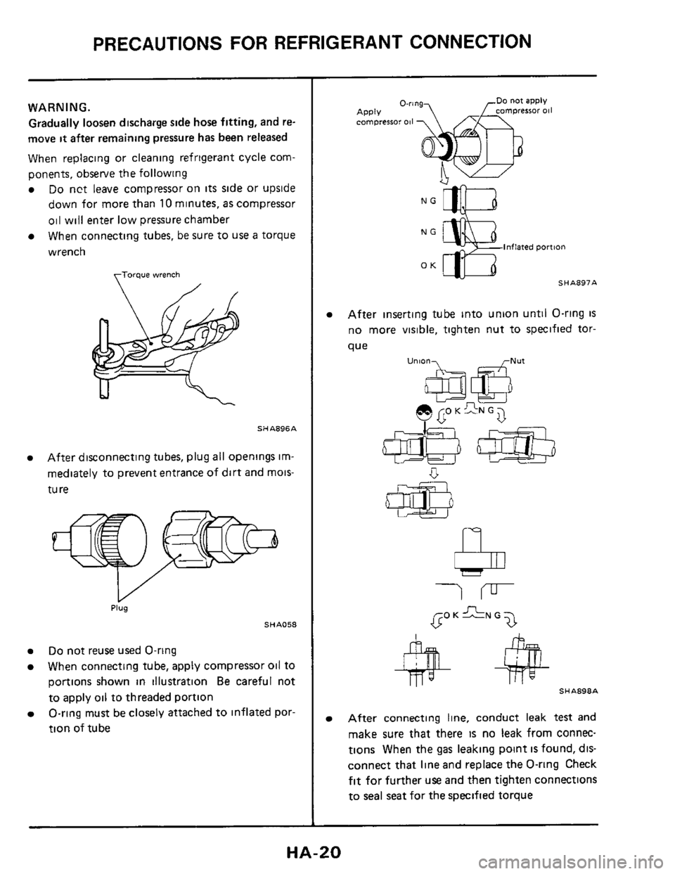
When connecting tubes, be sure to
use a torque
wrench
torque wrench
SHA896A
After disconnecting tubes, plug all openings im-
mediately to prevent entrance of dirt and mois-
tu
re
Plug
SHA058
Do not reuse used O-ring
When connecting tube, apply compressor oil to
portions shown in illustration
Be careful not
to apply oil to threaded portion
O-ring must be closely attached to inflated por-
tion of tube
NG
lnflaied pomon
OK - SHA897A
After inserting tube into union until O-ring is
no more visible, tighten nut to specified tor-
que
u"'06a e GO K GN G 7
b
SHA898A
After connecting line, conduct leak test and
make sure that there
IS no leak from connec-
tions When the
gas leaking point IS found, dis-
connect that line and replace the O-ring Check
fit for further use and then tighten connections
to seal seat for the specified torque
HA-20
Page 26 of 38
COMPRESSOR-Model MJS170
Leak Test
EVACUATE AND CONDUCT LEAK TEST
7 KV994C1552
SHA907A
Clutch Replacement
When removing shaft nut, hold clutch hub with
Tool
Tool No.: KV99412302 (J24878-1)
Using Tool KV994C5780, clutch hub can be
removed easily
SHA268A
When assembling clutch hub, adjust hub-to-
pulley clearance with shims
SHA272A
SHA908A
BREAK-IN OPERATION
When replacing compressor clutch assembly, do
not forget break-in operation, accomplished by
engaging and disengaging the clutch about thirty
times Break-in operation
raises the level of trans-
mitted torque
HA-26
Page 36 of 38

SERVICE DATA AND SPECIFICATIONS (S.D.S.)
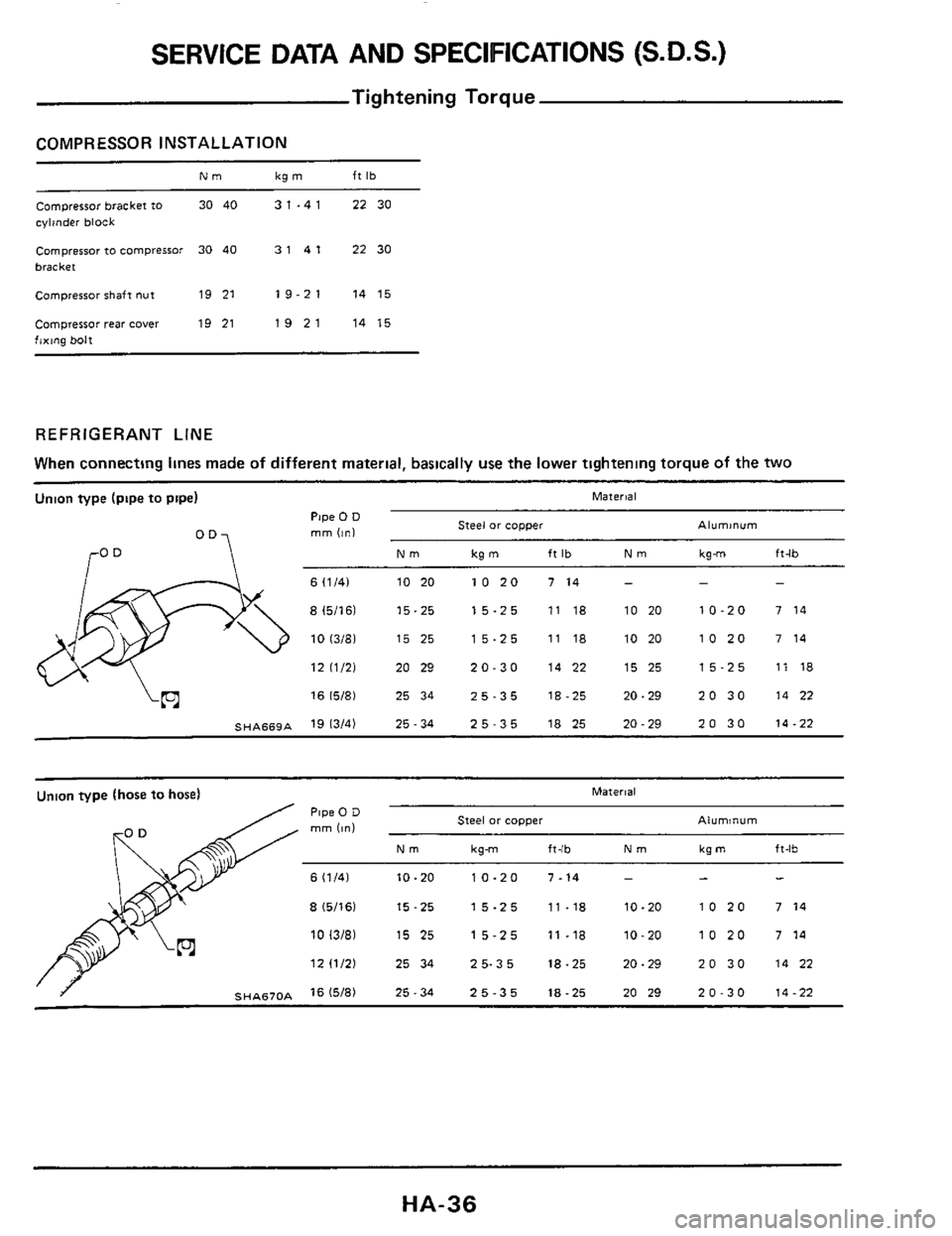
Tightening Torque
COMPRESSOR INSTALLATION
Compressor bracket to 30 40 3 1 .4 1 22 30
cylinder block
Compressor to compressor 30 40 3141 2230
bracket
Compressor shafl nut 19 21 19-21 14 15
Compressor rear cover 19 21 1921 1415
fixing bolt
REFRIGERANT LINE
When connecting lines made of different material, basically use the lower tightening torque of the two ~~
Union
type (pipe to pipe) Material
Pipe 0 D
mm (in) Steel or copper Aluminum
Nm kg m ft Ib Nm kgm ft-lb ro
6 11/41 10 20 10 20 7 14 - - -
8 15/16) 15-25 15-25 11 18 10 20 10-20 7 14
10 13/81 15 25 15-25 11 18 10 20 10 20 7 14
12 11/21 20 29 20-30 14 22 15 25 15-25 11 18
16 15/81 25 34 25-35 18-25 20-29 20 30 14 22
SHA669A 19 13/4) 25-34 25-35 18 25 20-29 20 30 14-22
Union type (hose to hose) Malerial
Pipe 0 D rnm Iin) Steel or copper Aluminum
Nm kg-m fl-lb Nm kg m ft-lb
6 11/41 10-20 10-20 7-14 - - -
8 15/161 15-25 15-25 11-18 10-20 10 20 7 14
10 13/81 15 25 15-25 11-18 10-20 10 20 7 14
12 11/21 2534 25-35 18-25 20-29 2030 1422
SHA670A I5I8) 25-34 25-35 18-25 20 29 20-30 14-22
HA-36
Page 37 of 38
SERVICE DATA AND SPECIFICATIONS (S.D.S.)
Tightening Torque (Cont'd)
Union type (hose to pipel
a Use tightening torcue for flexible hose
SHA671A
Plate type Bolt tYlX Tightening torque
Bolt Nominal Pitch diameter Nm kg-m ft-lb mm (in1 mm lini Grade 112e
M6 6 0 10 2361 1 0 10 0391 3 -4 03-04 22 29
4T M8 80103151 125100492) 8-11 08-11 58 80
M10 10 0 1.3 3941 1 5 IO 0591 16 22 1622 1216
M6 6 0 IO 2361 1 0 IO 0391 6 - 7 06 07 43-51
7T M8 80 10 3151 1 25 I004921 14 18 14-18 1013
M10 100103941 15100591 25 35 26-36 19-26
.3
HA-37'