Page 25 of 38
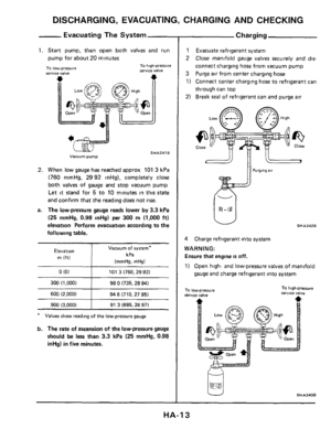
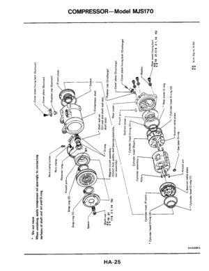
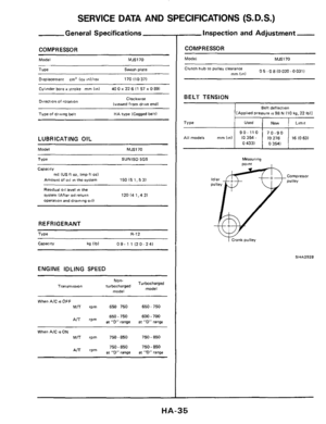
COMPRESSOR-Model MJS170
HA-25,
Page 26 of 38
COMPRESSOR-Model MJS170
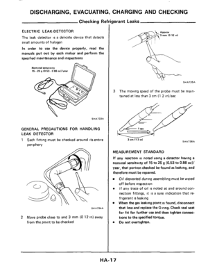
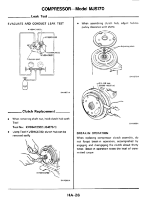
Leak Test
EVACUATE AND CONDUCT LEAK TEST
7 KV994C1552
SHA907A
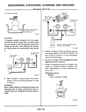
Clutch Replacement
When removing shaft nut, hold clutch hub with
Tool
Tool No.: KV99412302 (J24878-1)
Using Tool KV994C5780, clutch hub can be
removed easily
SHA268A
When assembling clutch hub, adjust hub-to-
pulley clearance with shims
SHA272A
SHA908A
BREAK-IN OPERATION
When replacing compressor clutch assembly, do
not forget break-in operation, accomplished by
engaging and disengaging the clutch about thirty
times Break-in operation
raises the level of trans-
mitted torque
HA-26
Page 27 of 38
COMPRESSOR-Model MJS170
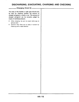
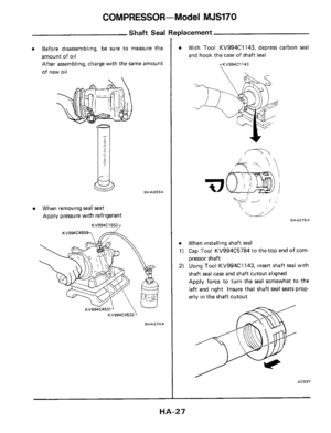
Shaft Seal Replacement
Before disassembling, be sure to measure the
amount of
oil
After assembling, charge with the same amount
of new oil
When removing seal seat
Apply pressure with refrigerant
KV994C15527
SHA033A
SHA274A
0 With Tool KV994C1 143, depress carbon seal
and hook the case of shaft seal
yKV994C1143
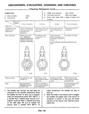
0 When installing shaft seal
1) Cap Tool KV994C5784 to the top end of corn-
pressor shaft
2) Using Tool KV994C1 143, insert shaft seal with
shaft
seal case and shaft cutout aligned
Apply force to turn the
seal somewhat to the
left and right insure that shaft seal seats prop-
erly in the shaft cutout
AC037
HA-27
Page 28 of 38
COMPRESSOR-Model MJS170
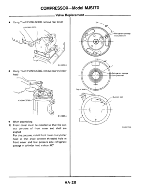
Valve Re
Using Tool KV99412330, remove rear cover
yKV9941 2330
SHAO38A
Using Tool KV994C5785, remove rear cylinder
head
SHA909A
When assembling
1) Front cover must be installed so that the cut-
out portions of front cover and
shell are
aligned
For this purpose, install front cover on cylinder
head
so that angle between threaded hole in
front cover and low pressure side refrtgerant
passage in cylinder head
is about 60"
acement
k
Refrigerant parrage
SHA276A
HA-28
Page 29 of 38
COMPRESSOR-Model MJS170
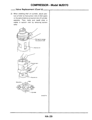
-Valve Replacement (Cont’d)-
2) When installing shell on cylinder, adjust post-
tion
of shell so that suction inlet of shell opens
in the same direction
as suction slot of cylinder
assembly
Then, make sure swash plate is
visible in suction inlet by removing suction
valve
Refrigeranr parsage (low presure sidel
SHA277A
HA-29
Page 30 of 38
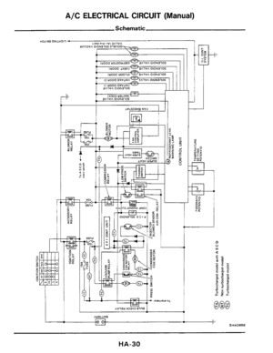
A/C ELECTRICAL CIRCUIT (Manual)
Schematic
I, AYlllWfB 1 - tl I' SHA249B
HA-30
Page 31 of 38
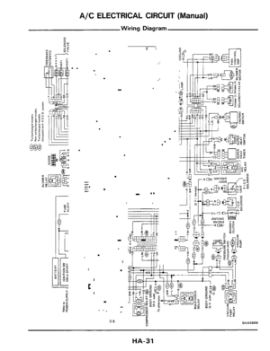
A/C ELECTRICAL CIRCUIT (Manual)
Wiring Diagram
.
.
... ... .... .. . ...
.
.
.
.
I
t
.
HA-31
Page 32 of 38
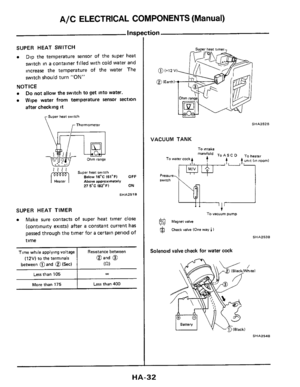
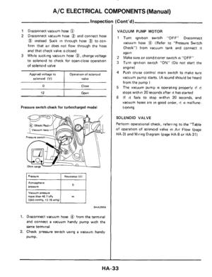
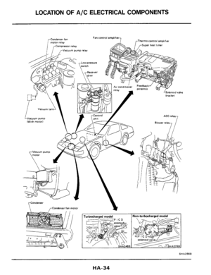
A/C ELECTRICAL COMPONENTS (Manual)
Time while applying voltage
(12V) to the terminals
between @and
@ (Sed
Inspc
Resistance between
@and
@
622)
SUPER HEAT SWITCH
a Dip the temperature sensor of the super heat
switch in
a container filled with cold water and
increase the temperature of the water The
switch should turn
"ON"
Do not allow the switch to get into water.
Wipe water from temperature sensor section
after checking
it
NOTICE
a
a
Super heat s.wlch
Thermometer
Ohm range __ - - ._ .- - -- .. . . ".
' ' ' ' Super hear switch Below 16'C 161°F) OFF Above approximately 27 5-C (82°F) ON
hb
SHA251B
More than 175 Less than 400
Less than 105 I co
SHA252B
VACUUM TANK
To intake manifold TO As To heater t,,t unit (An room) To warer cock
To vacuum pump
@ Magnet valve
Check valve (One way 1 )
SHAZ53B
Solenoid valve check for water cock
SHA254B
HA-32


 Front cover must be")
-
2) When installing shell on cylinder, adjust post-
tion
of shell so that suction inlet of shell opens
in the same direction
as suction")

Schematic
I, AYlllWfB 1 - tl I SHA249B
HA-30")

Wiring Diagram
.
.
... ... .... .. . ...
.
.
.
.
I
t
.
HA-31")

Time while applying voltage
(12V) to the terminals
between @and
@ (Sed
Inspc
Resistance between
@and
@
622)
SUPER HEAT SWITCH
a Dip the temperature")