1983 FIAT UNO roof
[x] Cancel search: roofPage 4 of 303
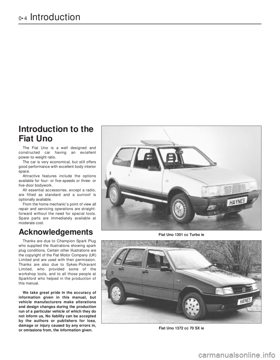
The Fiat Uno is a well designed and
constructed car having an excellent
power-to-weight ratio.
The car is very economical, but still offers
good performance with excellent body interior
space.
Attractive features include the options
available for four- or five-speeds or three- or
five-door bodywork.
All essential accessories, except a radio,
are fitted as standard and a sunroof is
optionally available.
From the home mechanic’s point of view all
repair and servicing operations are straight-
forward without the need for special tools.
Spare parts are immediately available at
moderate cost.
Acknowledgements
Thanks are due to Champion Spark Plug
who supplied the illustrations showing spark
plug conditions. Certain other illustrations are
the copyright of the Fiat Motor Company (UK)
Limited and are used with their permission.
Thanks are also due to Sykes-Pickavant
Limited, who provided some of the
workshop tools, and to all those people at
Sparkford who helped in the production of
this manual.
We take great pride in the accuracy of
information given in this manual, but
vehicle manufacturers make alterations
and design changes during the production
run of a particular vehicle of which they do
not inform us, No liability can be accepted
by the authors or publishers for loss,
damage or injury caused by any errors in,
or omissions from, the information given.
0•4Introduction
Introduction to the
Fiat Uno
Fiat Uno 1301 cc Turbo ie
Fiat Uno 1372 cc 70 SX ie
Page 65 of 303
7 Carburettor idle speed and
mixture- adjustment
4
1All carburettors have their mixture
adjustment set in production. The screw is
fitted with a tamperproof cap.
2Under normal circumstances, only the idle
speed screw need be adjusted to set the
engine idle speed to the specified level.
3Before attempting to adjust the idle speed
or mixture, it is important to have the ignition
and valve clearances correctly set and the
engine at normal operating temperature with
the air cleaner fitted.
4Where the mixture must be adjusted, prise
out the tamperproof plug and turn the mixture
screw in to weaken or out to enrich the
mixture until the engine runs smoothly without
any tendency to “hunt”.
5Ideally an exhaust gas analyser should be
used to make sure that the CO level is within
the specified range.
6Once the mixture has been correctly set,
re-adjust the idle speed screw.
8 Carburettor-
removal and refitting
2
1Remove the air cleaner.
2Disconnect the flow and return fuel hoses
from the carburettor and plug them.3Disconnect the coolant hoses from the
carburettor throttle valve plate block.
Provided the cooling system is cold and not
under pressure there should be almost no loss
of coolant. Tie the hoses up as high as
possible with a piece of wire.
4Disconnect the vacuum and vent hoses
from the carburettor.
5Disconnect the throttle and choke controls
from the carburettor.
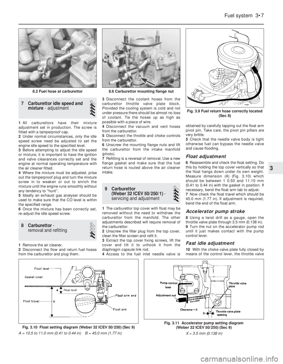
6Unscrew the mounting flange nuts and lift
the carburettor from the intake manifold
(photo).
7Refitting is a reversal of removal. Use a new
flange gasket and make sure that the fuel
return hose is routed above the air cleaner
intake.
9 Carburettor
(Weber 32 ICEV 50/250/1)-
servicing and adjustment
4
1The carburettor top cover with float may be
removed without the need to withdraw the
carburettor from the manifold. The other
adjustments described will require removal of
the carburettor.
2Unscrew the filter plug from the top cover,
clean the filter screen and refit it.
3Extract the top cover fixing screws, lift the
cover and tilt it to unhook it from the
diaphragm capsule link rod.
4Access to the fuel inlet needle valve isobtained by carefully tapping out the float arm
pivot pin. Take care, the pivot pin pillars are
very brittle.
5Check that the needle valve body is tight
otherwise fuel can bypass the needle valve
and cause flooding.
Float adjustment
6Reassemble and check the float setting. Do
this by holding the top cover vertically so that
the float hangs down under its own weight.
Measure dimension (A) (Fig. 3.10) which
should be between 1 0.50 and 11.10 mm
(0.41 to 0.44 in) with the gasket in position. If
necessary, bend the float arm tab to adjust.
7Now check the float travel which should be
45.0 mm (1.77 in). If adjustment is required,
bend the end of the float arm.
Accelerator pump stroke
8Using a twist drill as a gauge, open the
throttle valve plate through 3.5 mm (0.138 in).
9Turn the nut on the accelerator pump rod
until it just makes contact with the pump
control lever.
Fast idle adjustment
10With the choke valve plate fully closed by
means of the control lever, the throttle valve
Fuel system 3•7
Fig. 3.9 Fuel return hose correctly located
(Sec 8)
8.6 Carburettor mounting flange nut8.2 Fuel hose at carburettor
Fig. 3.10 Float setting diagram (Weber 32 ICEV 50/250) (Sec 9)
A = 10.5 to 11.0 mm (0.41 to 0.44 in) B = 45.0 mm (1.77 in)Fig. 3.11 Accelerator pump setting diagram
(Weber 32 ICEV 50/250) (Sec 9)
X = 3.5 mm (0.138 in)
3
Page 91 of 303

1 General description
The electrical system is of 12 volt negative
earth type and employs a belt-driven
alternator and a pre-engaged type starter
motor.
The models in the range are all adequately
equipped with electrical accessories, while SX
versions also have power windows and
centralised door locking plus a check control
system (Section 34).
2 Battery- inspection, charging,
removal and refitting
2
1The battery is of maintenance-free type and
under normal circumstances, no topping up
will be required, but regularly check that the
electrolyte level is between the minimum and
maximum lines on the translucent battery
casing.
2If the electrolyte level does drop below theminimum line, suspect a leak in the battery
casing or that the alternator is overcharging. If
the latter is the case, rectify the alternator fault
and then prise out the two rectangular plugs
from the top of the battery and top up with
distilled or purified water.
3Always keep the battery terminals clean
and smear them with petroleum jelly to
prevent corrosion.
4The battery will normally be kept fully
charged by the alternator, but it is possible for
the battery to become discharged if the daily
mileage is very low with much use being
made of the starter and electrical accessories.
5When the battery begins to deteriorate with
age it may also require a boost from a mains
charger.
6Disconnect both battery leads before
connecting the mains charger. 7To remove the battery from the car, first
disconnect the leads from the battery
terminals (earth first) and then unscrew the
securing clamp from the casing projection at
the base of the casing (photo).
8Lift the battery from its mounting platform.
Refitting is a reversal of removal. Reconnect
the earth cable last.
Fuses
Circuit protected Fuse rating (A)
1 Stop lamps, direction indicator lamps, instrument panel warning
lamps, tachometer economy gauge, check control system . . . . . . 10
2 Windscreen wiper and washer, rear screen wiper/washer, check
system panel illumination . . . . . . . . . . . . . . . . . . . . . . . . . . . . . . . . 20
3 Left front parking, right rear tail lamp, cigar lighter illumination,
heater control and clock, digital clock illumination . . . . . . . . . . . . . 7.5
4 Right front parking lamp and left rear tail lamp, instrument panel
illumination and rear number plate lamp . . . . . . . . . . . . . . . . . . . . . 7.5
5 Left-hand dipped headlamp, rear foglamps . . . . . . . . . . . . . . . . . . 10
6 Right-hand dipped headlamp . . . . . . . . . . . . . . . . . . . . . . . . . . . . . 10
7 Left-hand headlamp (main beam) . . . . . . . . . . . . . . . . . . . . . . . . . . 10
8 Right-hand headlamp (main beam) . . . . . . . . . . . . . . . . . . . . . . . . . 10
9 Engine cooling fan and horn (Comfort) . . . . . . . . . . . . . . . . . . . . . . 25
10 Heater booster fan, digital clock map reading lamp . . . . . . . . . . . . 20
11 Heated tailgate glass . . . . . . . . . . . . . . . . . . . . . . . . . . . . . . . . . . . 20
12 Courtesy lamps, cigar lighter, radio power feed, disc pad
sensors, economy gauge (ES models) . . . . . . . . . . . . . . . . . . . . . . 10
13 Hazard warning lamps . . . . . . . . . . . . . . . . . . . . . . . . . . . . . . . . . . 10
14 Spare (Comfort), Horn (Super) . . . . . . . . . . . . . . . . . . . . . . . . . . . . 20
BulbsWattage
Headlamp . . . . . . . . . . . . . . . . . . . . . . . . . . . . . . . . . . . . . . . . . . . . . . . . 40/45 or Halogen H4 60/55
Front parking . . . . . . . . . . . . . . . . . . . . . . . . . . . . . . . . . . . . . . . . . . . . . 5
Side repeater . . . . . . . . . . . . . . . . . . . . . . . . . . . . . . . . . . . . . . . . . . . . . 5
Tail . . . . . . . . . . . . . . . . . . . . . . . . . . . . . . . . . . . . . . . . . . . . . . . . . . . . 5
Stop . . . . . . . . . . . . . . . . . . . . . . . . . . . . . . . . . . . . . . . . . . . . . . . . . . . . 21
Reversing . . . . . . . . . . . . . . . . . . . . . . . . . . . . . . . . . . . . . . . . . . . . . . . . 21
Rear foglamp . . . . . . . . . . . . . . . . . . . . . . . . . . . . . . . . . . . . . . . . . . . . . 21
Direction indicator . . . . . . . . . . . . . . . . . . . . . . . . . . . . . . . . . . . . . . . . . 21
Rear number plate . . . . . . . . . . . . . . . . . . . . . . . . . . . . . . . . . . . . . . . . . 5
Courtesy lamp (roof) . . . . . . . . . . . . . . . . . . . . . . . . . . . . . . . . . . . . . . . . 10
Courtesy lamp (pillar) . . . . . . . . . . . . . . . . . . . . . . . . . . . . . . . . . . . . . . . 5
Warning and indicator . . . . . . . . . . . . . . . . . . . . . . . . . . . . . . . . . . . . . . Wedge base
Torque wrench settingsNm lbf ft
Alternator mounting and adjustment nuts . . . . . . . . . . . . . . . . . . . . . . . 50 87
Starter motor bolts . . . . . . . . . . . . . . . . . . . . . . . . . . . . . . . . . . . . . . . . . 48 35
9•2 Electrical system
2.7 Battery clamp
If battery terminal corrosion
has occurred, it may be
neutralised by applying
sodium bicarbonate or
household ammonia.
Page 97 of 303
20 Interior lamps-
bulb renewal
1
Courtesy lamp
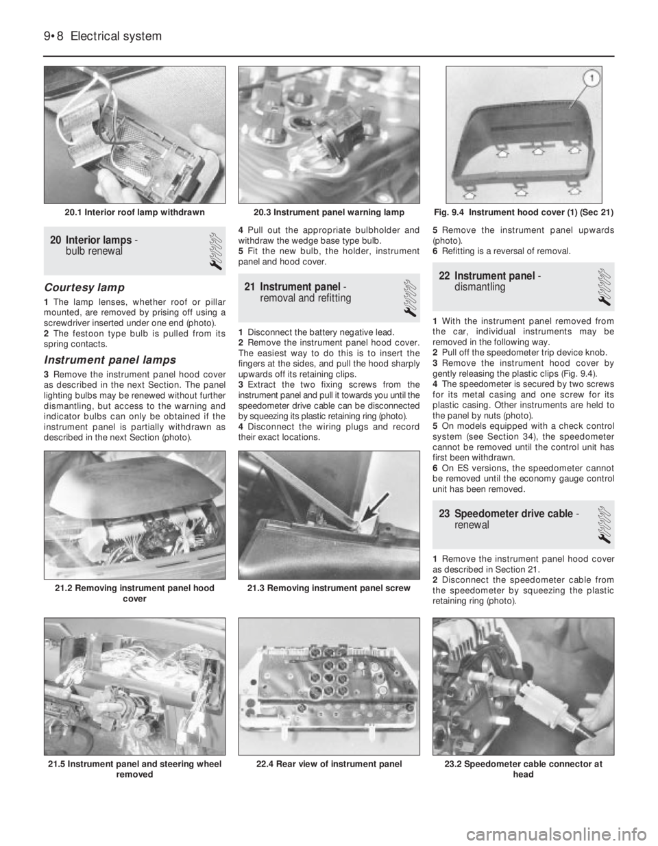
1The lamp lenses, whether roof or pillar
mounted, are removed by prising off using a
screwdriver inserted under one end (photo).
2The festoon type bulb is pulled from its
spring contacts.
Instrument panel lamps
3Remove the instrument panel hood cover
as described in the next Section. The panel
lighting bulbs may be renewed without further
dismantling, but access to the warning and
indicator bulbs can only be obtained if the
instrument panel is partially withdrawn as
described in the next Section (photo). 4Pull out the appropriate bulbholder and
withdraw the wedge base type bulb.
5Fit the new bulb, the holder, instrument
panel and hood cover.
21 Instrument panel-
removal and refitting
1
1Disconnect the battery negative lead.
2Remove the instrument panel hood cover.
The easiest way to do this is to insert the
fingers at the sides, and pull the hood sharply
upwards off its retaining clips.
3Extract the two fixing screws from the
instrument panel and pull it towards you until the
speedometer drive cable can be disconnected
by squeezing its plastic retaining ring (photo).
4Disconnect the wiring plugs and record
their exact locations. 5Remove the instrument panel upwards
(photo).
6Refitting is a reversal of removal.
22 Instrument panel-
dismantling
1
1With the instrument panel removed from
the car, individual instruments may be
removed in the following way.
2Pull off the speedometer trip device knob.
3Remove the instrument hood cover by
gently releasing the plastic clips (Fig. 9.4).
4The speedometer is secured by two screws
for its metal casing and one screw for its
plastic casing. Other instruments are held to
the panel by nuts (photo).
5On models equipped with a check control
system (see Section 34), the speedometer
cannot be removed until the control unit has
first been withdrawn.
6On ES versions, the speedometer cannot
be removed until the economy gauge control
unit has been removed.
23 Speedometer drive cable-
renewal
1
1Remove the instrument panel hood cover
as described in Section 21.
2Disconnect the speedometer cable from
the speedometer by squeezing the plastic
retaining ring (photo).
9•8 Electrical system
23.2 Speedometer cable connector at
head22.4 Rear view of instrument panel21.5 Instrument panel and steering wheel
removed
21.3 Removing instrument panel screw21.2 Removing instrument panel hood
cover
Fig. 9.4 Instrument hood cover (1) (Sec 21)20.3 Instrument panel warning lamp20.1 Interior roof lamp withdrawn
Page 110 of 303
release its top coil from the strut upper
mounting, hold the flats on the strut spindle
and unscrew the spindle nut.
8Take off the upper mounting components
and the clamped coil spring. The clamps need
not be removed if the spring is to be fitted to a
new strut.
9Commence reassembly by fitting the coil
spring onto the strut. Make sure that the
smaller coil is at the top and the lower coil is
up against its end stop in the spring seat.
10Check that the strut boot is in position.
11Fit the upper mounting components and
screw on the spindle nut.
12Gently release the spring clamps and
remove them.
13Refit the strut to the car by reversing the
removal operations.
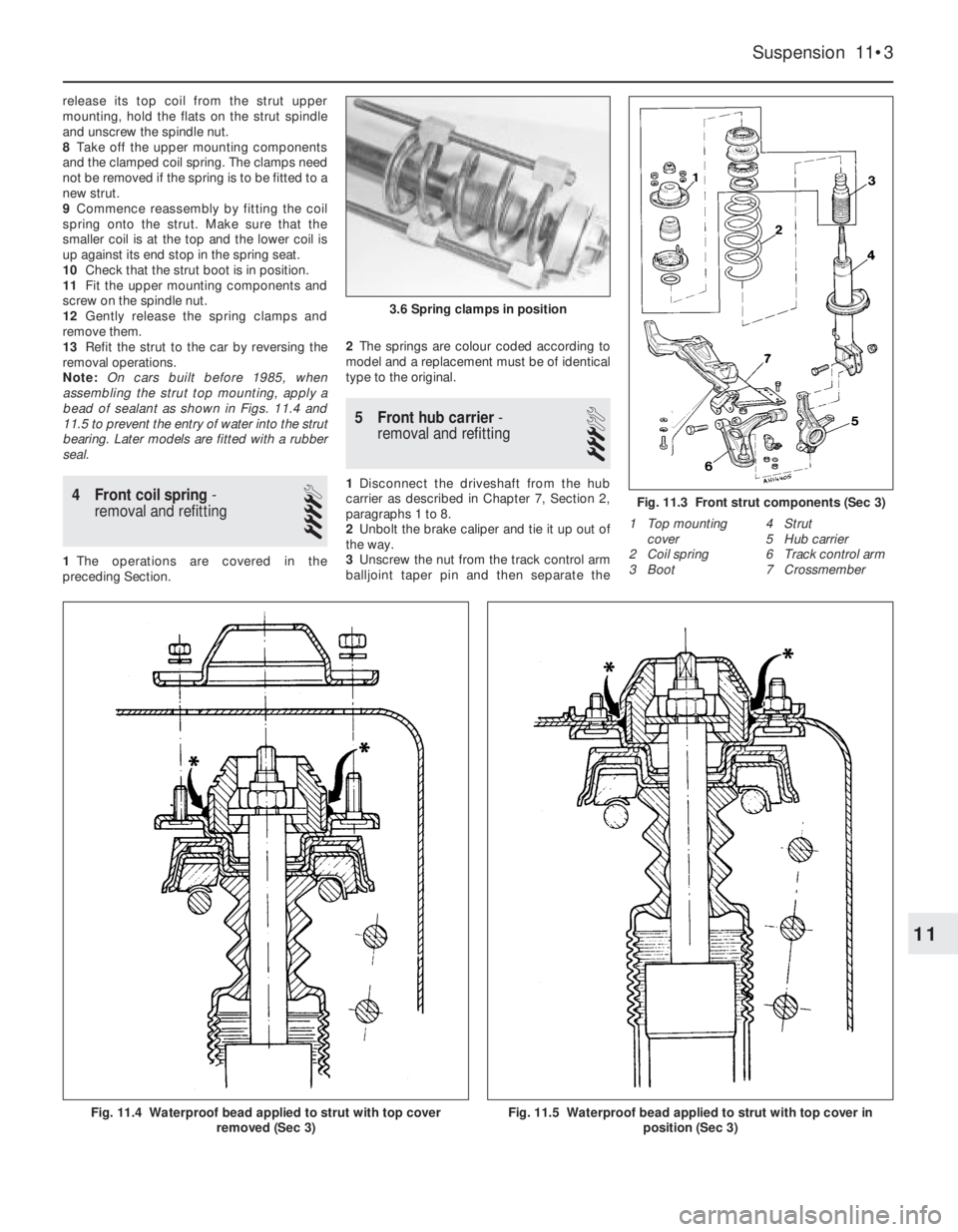
Note: On cars built before 1985, when
assembling the strut top mounting, apply a
bead of sealant as shown in Figs. 11.4 and
11.5 to prevent the entry of water into the strut
bearing. Later models are fitted with a rubber
seal.
4 Front coil spring-
removal and refitting
4
1The operations are covered in the
preceding Section.2The springs are colour coded according to
model and a replacement must be of identical
type to the original.
5 Front hub carrier-
removal and refitting
3
1Disconnect the driveshaft from the hub
carrier as described in Chapter 7, Section 2,
paragraphs 1 to 8.
2Unbolt the brake caliper and tie it up out of
the way.
3Unscrew the nut from the track control arm
balljoint taper pin and then separate the
Suspension 11•3
1 Top mounting
cover
2 Coil spring
3 Boot4 Strut
5 Hub carrier
6 Track control arm
7 Crossmember
Fig. 11.3 Front strut components (Sec 3)
3.6 Spring clamps in position
Fig. 11.4 Waterproof bead applied to strut with top cover
removed (Sec 3)Fig. 11.5 Waterproof bead applied to strut with top cover in
position (Sec 3)
11
Page 114 of 303
12
For dimensions, weights etc. refer to the Introductory Section of this Manual.
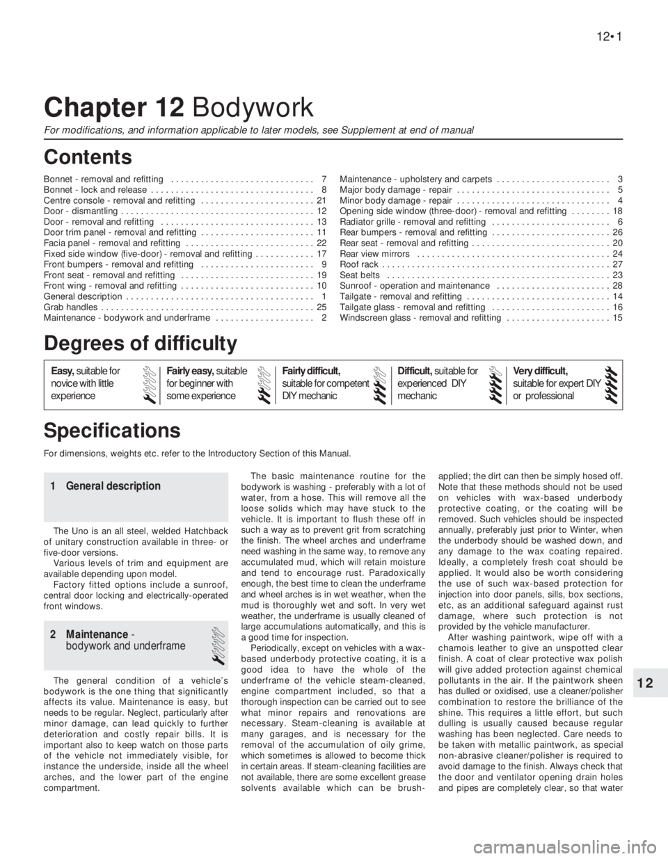
Chapter 12 Bodywork
For modifications, and information applicable to later models, see Supplement at end of manual
Bonnet - removal and refitting . . . . . . . . . . . . . . . . . . . . . . . . . . . . . 7
Bonnet - lock and release . . . . . . . . . . . . . . . . . . . . . . . . . . . . . . . . . 8
Centre console - removal and refitting . . . . . . . . . . . . . . . . . . . . . . . 21
Door - dismantling . . . . . . . . . . . . . . . . . . . . . . . . . . . . . . . . . . . . . . . 12
Door - removal and refitting . . . . . . . . . . . . . . . . . . . . . . . . . . . . . . . 13
Door trim panel - removal and refitting . . . . . . . . . . . . . . . . . . . . . . . 11
Facia panel - removal and refitting . . . . . . . . . . . . . . . . . . . . . . . . . . 22
Fixed side window (five-door) - removal and refitting . . . . . . . . . . . . 17
Front bumpers - removal and refitting . . . . . . . . . . . . . . . . . . . . . . . 9
Front seat - removal and refitting . . . . . . . . . . . . . . . . . . . . . . . . . . . 19
Front wing - removal and refitting . . . . . . . . . . . . . . . . . . . . . . . . . . . 10
General description . . . . . . . . . . . . . . . . . . . . . . . . . . . . . . . . . . . . . . 1
Grab handles . . . . . . . . . . . . . . . . . . . . . . . . . . . . . . . . . . . . . . . . . . . 25
Maintenance - bodywork and underframe . . . . . . . . . . . . . . . . . . . . 2Maintenance - upholstery and carpets . . . . . . . . . . . . . . . . . . . . . . . 3
Major body damage - repair . . . . . . . . . . . . . . . . . . . . . . . . . . . . . . . 5
Minor body damage - repair . . . . . . . . . . . . . . . . . . . . . . . . . . . . . . . 4
Opening side window (three-door) - removal and refitting . . . . . . . . 18
Radiator grille - removal and refitting . . . . . . . . . . . . . . . . . . . . . . . . 6
Rear bumpers - removal and refitting . . . . . . . . . . . . . . . . . . . . . . . . 26
Rear seat - removal and refitting . . . . . . . . . . . . . . . . . . . . . . . . . . . . 20
Rear view mirrors . . . . . . . . . . . . . . . . . . . . . . . . . . . . . . . . . . . . . . . 24
Roof rack . . . . . . . . . . . . . . . . . . . . . . . . . . . . . . . . . . . . . . . . . . . . . . 27
Seat belts . . . . . . . . . . . . . . . . . . . . . . . . . . . . . . . . . . . . . . . . . . . . . 23
Sunroof - operation and maintenance . . . . . . . . . . . . . . . . . . . . . . . 28
Tailgate - removal and refitting . . . . . . . . . . . . . . . . . . . . . . . . . . . . . 14
Tailgate glass - removal and refitting . . . . . . . . . . . . . . . . . . . . . . . . 16
Windscreen glass - removal and refitting . . . . . . . . . . . . . . . . . . . . . 15
12•1
Specifications Contents
Easy,suitable for
novice with little
experienceFairly easy,suitable
for beginner with
some experienceFairly difficult,
suitable for competent
DIY mechanic
Difficult,suitable for
experienced DIY
mechanicVery difficult,
suitable for expert DIY
or professional
Degrees of difficulty
54321
1 General description
The Uno is an all steel, welded Hatchback
of unitary construction available in three- or
five-door versions.
Various levels of trim and equipment are
available depending upon model.
Factory fitted options include a sunroof,
central door locking and electrically-operated
front windows.
2 Maintenance-
bodywork and underframe
1
The general condition of a vehicle’s
bodywork is the one thing that significantly
affects its value. Maintenance is easy, but
needs to be regular. Neglect, particularly after
minor damage, can lead quickly to further
deterioration and costly repair bills. It is
important also to keep watch on those parts
of the vehicle not immediately visible, for
instance the underside, inside all the wheel
arches, and the lower part of the engine
compartment.The basic maintenance routine for the
bodywork is washing - preferably with a lot of
water, from a hose. This will remove all the
loose solids which may have stuck to the
vehicle. It is important to flush these off in
such a way as to prevent grit from scratching
the finish. The wheel arches and underframe
need washing in the same way, to remove any
accumulated mud, which will retain moisture
and tend to encourage rust. Paradoxically
enough, the best time to clean the underframe
and wheel arches is in wet weather, when the
mud is thoroughly wet and soft. In very wet
weather, the underframe is usually cleaned of
large accumulations automatically, and this is
a good time for inspection.
Periodically, except on vehicles with a wax-
based underbody protective coating, it is a
good idea to have the whole of the
underframe of the vehicle steam-cleaned,
engine compartment included, so that a
thorough inspection can be carried out to see
what minor repairs and renovations are
necessary. Steam-cleaning is available at
many garages, and is necessary for the
removal of the accumulation of oily grime,
which sometimes is allowed to become thick
in certain areas. If steam-cleaning facilities are
not available, there are some excellent grease
solvents available which can be brush-applied; the dirt can then be simply hosed off.
Note that these methods should not be used
on vehicles with wax-based underbody
protective coating, or the coating will be
removed. Such vehicles should be inspected
annually, preferably just prior to Winter, when
the underbody should be washed down, and
any damage to the wax coating repaired.
Ideally, a completely fresh coat should be
applied. It would also be worth considering
the use of such wax-based protection for
injection into door panels, sills, box sections,
etc, as an additional safeguard against rust
damage, where such protection is not
provided by the vehicle manufacturer.
After washing paintwork, wipe off with a
chamois leather to give an unspotted clear
finish. A coat of clear protective wax polish
will give added protection against chemical
pollutants in the air. If the paintwork sheen
has dulled or oxidised, use a cleaner/polisher
combination to restore the brilliance of the
shine. This requires a little effort, but such
dulling is usually caused because regular
washing has been neglected. Care needs to
be taken with metallic paintwork, as special
non-abrasive cleaner/polisher is required to
avoid damage to the finish. Always check that
the door and ventilator opening drain holes
and pipes are completely clear, so that water
Page 119 of 303
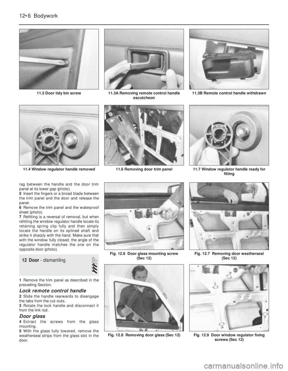
rag between the handle and the door trim
panel at its lower gap (photo).
5Insert the fingers or a broad blade between
the trim panel and the door and release the
panel.
6Remove the trim panel and the waterproof
sheet (photo).
7Refitting is a reversal of removal, but when
refitting the window regulator handle locate its
retaining spring clip fully and then simply
locate the handle on its splined shaft and
strike it sharply with the hand. Make sure that
with the window fully closed, the angle of the
regulator handle matches the one on the
opposite door (photo).
12 Door- dismantling
3
1Remove the trim panel as described in the
preceding Section.
Lock remote control handle
2Slide the handle rearwards to disengage
the tabs from the cut-outs.
3Rotate the lock handle and disconnect it
from the link rod.
Door glass
4Extract the screws from the glass
mounting.
5With the glass fully lowered, remove the
weatherseal strips from the glass slot in the
door.
Fig. 12.9 Door window regulator fixing
screws (Sec 12)Fig. 12.8 Removing door glass (Sec 12)
Fig. 12.7 Removing door weatherseal
(Sec 12)Fig. 12.6 Door glass mounting screw
(Sec 12)
12•6 Bodywork
11.7 Window regulator handle ready for
fitting11.6 Removing door trim panel11.4 Window regulator handle removed
11.3B Remote control handle withdrawn11.3A Removing remote control handle
escutcheon11.2 Door tidy bin screw
Page 121 of 303
speakers, central door locking or power
operated windows, the electrical leads must be
disconnected and withdrawn through the
flexible duct before the door hinges are
unbolted. Disconnection will require removal of
the door trim panel as described in Section 11.
5It is recommended that the door is unbolted
from the hinge, leaving the hinge attached to
the body pillar.
6Refitting is a reversal of removal, but leave
the bolts finger tight until the door has been
gently closed and its alignment checked.
7The door can be moved up and down or
sideways using the travel provided by the
elongated bolt holes.
8If the door is not flush with the adjacent
body panels then shims should be inserted
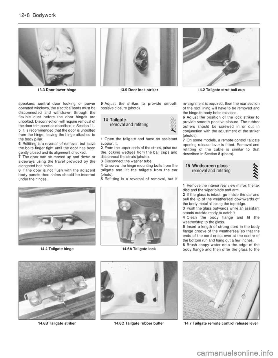
under the hinges.9Adjust the striker to provide smooth
positive closure (photo).
14 Tailgate-
removal and refitting
1
1Open the tailgate and have an assistant
support it.
2From the upper ends of the struts, prise out
the locking wedges from the ball cups and
disconnect the struts (photo).
3Disconnect the washer tube.
4Unscrew the hinge mounting bolts from the
tailgate and lift the tailgate from the car
(photo).
5Refitting is a reversal of removal, but ifre-alignment is required, then the rear section
of the roof lining will have to be removed and
the hinge to body bolts released.
6Adjust the position of the lock striker to
provide smooth positive closure. The rubber
buffers should be screwed in or out in
conjunction with the adjustment of the striker
(photos).
7On some models, a remote control tailgate
opening release lever is fitted. Removal and
refitting of the cable is similar to that
described in Section 8 (photo).
15 Windscreen glass-
removal and refitting
5
1Remove the interior rear view mirror, the tax
disc and the wiper blade and arm.
2If the glass is intact, go inside the car and
pull the lip of the weatherseal downwards off
the body metal all along the top edge.
3Push the glass outwards while an assistant
stands outside ready to catch it.
4Clean the body flange and fit the
weatherstrip to the glass.
5Insert a length of strong cord in the body
flange groove of the weatherseal so that the
ends of the cord cross over at the centre of
the bottom run and hang out a few inches.
6Brush soapy water onto the edge of the
body flange and then offer the glass to the
12•8 Bodywork
14.7 Tailgate remote control release lever14.6C Tailgate rubber buffer14.6B Tailgate striker
14.6A Tailgate lock14.4 Tailgate hinge
14.2 Tailgate strut ball cup13.9 Door lock striker13.3 Door lower hinge