1983 FIAT UNO wheel alignment
[x] Cancel search: wheel alignmentPage 171 of 303

new oil seal, ensuring that it is correctly
orientated, and drive it squarely into position.
149Refit all disturbed components.
Flywheel - removal,
inspection and refitting#
150If not already done, remove the clutch as
described in Chapter 5.
151Prevent the flywheel from turning by
jamming the ring gear teeth, or by bolting a
strap between the flywheel and the cylinder
block.
152Make alignment marks on the flywheel
and the end of the crankshaft, so that the
flywheel can be refitted in its original position.
153Unscrew the securing bolts and remove
the washer plate, then withdraw the flywheel.
Do not drop it, it is very heavy.
154With the flywheel removed, the ring gear
can be examined for wear and damage.
155If the ring gear is badly worn or has
missing teeth it should be renewed. The old
ring gear can be removed from the flywheel by
cutting a notch between two teeth with a
hacksaw and then splitting it with a cold
chisel. Wear eye protection when doing this.
156Fitting of a new ring gear requires heating
the ring to a temperature of 80ºC (176ºF). Do
not overheat, or the hard-wearing properties
will be lost. The gear has a chamfered inner
edge which should fit against the shoulder on
the flywheel. When hot enough, place the gear
in position quickly, tapping it home ifnecessary, and let it cool naturally without
quenching in any way.
157Ensure that the mating faces are clean,
then locate the flywheel on the rear of the
crankshaft, aligning the previously made
marks on the flywheel and crankshaft.
158Fit the washer plate, and insert the
securing bolts, then prevent the flywheel from
turning as described in paragraph 151 whilst
the bolts are tightened progressively to the
specified torque setting in a diagonal
sequence (photos).
159If applicable, refit the clutch as described
in Chapter 5.
Sump -
removal and refittingÁ
160Drain the engine oil from the sump as
described in Chapter 1.
161Disconnect the lead from the engine oil
level sensor in the sump.
162Unscrew and remove the bolts retaining the
gear linkage mounting bracket (where applicable)
and the clutch housing lower cover bolts.
Remove the cover from the clutch housing.
163Unscrew and remove the sump retaining
bolts and nuts and lower the sump from the
crankcase. Recover the gasket.
164Clean all traces of old gasket from the
sump, crankcase and both oil seal housing
mating surfaces.
165Commence reassembly by applying
sealing compound (FIAT No. 5882442 orequivalent) to the joints between the
crankshaft front and rear oil seal housings and
the mating face of the crankcase (photo).
166Locate the new gasket in position on the
crankcase then fit the sump. As it is fitted it
will need to be twisted to avoid fouling the oil
pump unit. Refit the retaining bolts and nuts
and tighten them to the specified torque
(photos).
167Check that the sump drain plug is refitted
and fully tightened. If the engine is in the car,
top up the engine oil level.
Oil pump - removal,
checking and refittingª
168Drain the engine oil and remove the
sump as described in the previous
sub-Section.
169Unscrew the retaining bolts then
withdraw the oil pump and intake pipe/filter
from its location within the crankcase.
Remove the gasket.
170If oil pump wear is suspected, first check
the cost and availability of new parts and the
cost of a new pump. Then examine the pump
as described below and decide whether
renewal or repair is the best course of action.
171Unscrew the three securing bolts and
remove the oil pump cover (photo). Note that
as the cover is removed, the oil pressure relief
valve components will be released.
172Recover the oil pressure relief valve,
spring and spring seat.
13•46 Supplement: Revisions and information on later models
7B.166C . . . and insert the retaining bolts7B.166B . . . refit the sump . . .7B.166A Locate the new gasket . . .
7B.165 Apply sealant to the front oil seal
housing/cylinder block joint7B.158B . . . tighten the bolts to the
specified torque7B.158A Locate the flywheel, washer plate
and bolts . . .
Page 214 of 303

Ignition unit
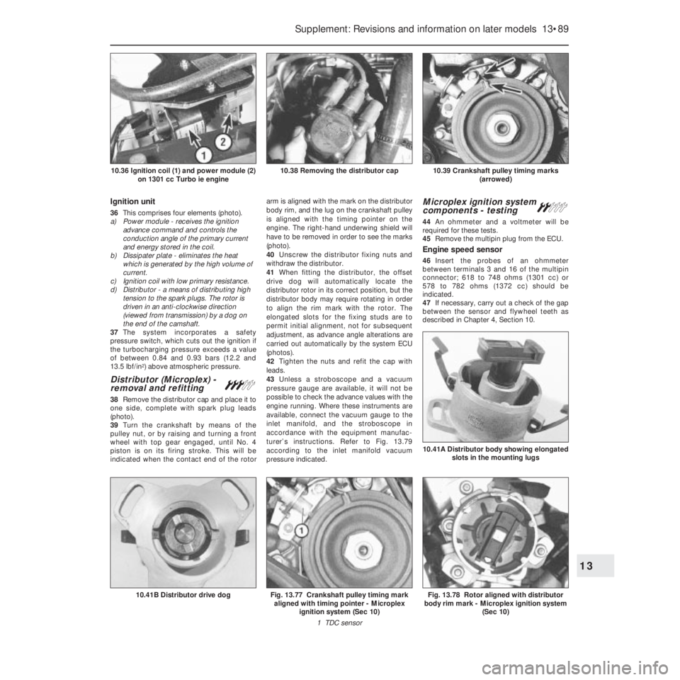
36This comprises four elements (photo).
a) Power module - receives the ignition
advance command and controls the
conduction angle of the primary current
and energy stored in the coil.
b) Dissipater plate - eliminates the heat
which is generated by the high volume of
current.
c) Ignition coil with low primary resistance.
d) Distributor - a means of distributing high
tension to the spark plugs. The rotor is
driven in an anti-clockwise direction
(viewed from transmission) by a dog on
the end of the camshaft.
37The system incorporates a safety
pressure switch, which cuts out the ignition if
the turbocharging pressure exceeds a value
of between 0.84 and 0.93 bars (12.2 and
13.5 lbf/in
2) above atmospheric pressure.
Distributor (Microplex) -
removal and refitting#
38Remove the distributor cap and place it to
one side, complete with spark plug leads
(photo).
39Turn the crankshaft by means of the
pulley nut, or by raising and turning a front
wheel with top gear engaged, until No. 4
piston is on its firing stroke. This will be
indicated when the contact end of the rotorarm is aligned with the mark on the distributor
body rim, and the lug on the crankshaft pulley
is aligned with the timing pointer on the
engine. The right-hand underwing shield will
have to be removed in order to see the marks
(photo).
40Unscrew the distributor fixing nuts and
withdraw the distributor.
41When fitting the distributor, the offset
drive dog will automatically locate the
distributor rotor in its correct position, but the
distributor body may require rotating in order
to align the rim mark with the rotor. The
elongated slots for the fixing studs are to
permit initial alignment, not for subsequent
adjustment, as advance angle alterations are
carried out automatically by the system ECU
(photos).
42Tighten the nuts and refit the cap with
leads.
43Unless a stroboscope and a vacuum
pressure gauge are available, it will not be
possible to check the advance values with the
engine running. Where these instruments are
available, connect the vacuum gauge to the
inlet manifold, and the stroboscope in
accordance with the equipment manufac-
turer’s instructions. Refer to Fig. 13.79
according to the inlet manifold vacuum
pressure indicated.
Microplex ignition system
components - testing ª
44An ohmmeter and a voltmeter will be
required for these tests.
45Remove the multipin plug from the ECU.
Engine speed sensor
46Insert the probes of an ohmmeter
between terminals 3 and 16 of the multipin
connector; 618 to 748 ohms (1301 cc) or
578 to 782 ohms (1372 cc) should be
indicated.
47If necessary, carry out a check of the gap
between the sensor and flywheel teeth as
described in Chapter 4, Section 10.
Supplement: Revisions and information on later models 13•89
10.39 Crankshaft pulley timing marks
(arrowed)10.38 Removing the distributor cap10.36 Ignition coil (1) and power module (2)
on 1301 cc Turbo ie engine
Fig. 13.78 Rotor aligned with distributor
body rim mark - Microplex ignition system
(Sec 10)
10.41A Distributor body showing elongated
slots in the mounting lugs
Fig. 13.77 Crankshaft pulley timing mark
aligned with timing pointer - Microplex
ignition system (Sec 10)
1 TDC sensor10.41B Distributor drive dog
13
Page 285 of 303

REF•2MOT Test Checks
Seat belts and seats
Note: The following checks are applicable to
all seat belts, front and rear.
MExamine the webbing of all the belts
(including rear belts if fitted) for cuts, serious
fraying or deterioration. Fasten and unfasten
each belt to check the buckles. If applicable,
check the retracting mechanism. Check the
security of all seat belt mountings accessible
from inside the vehicle.
MThe front seats themselves must be
securely attached and the backrests must
lock in the upright position.
Doors
MBoth front doors must be able to be opened
and closed from outside and inside, and must
latch securely when closed.
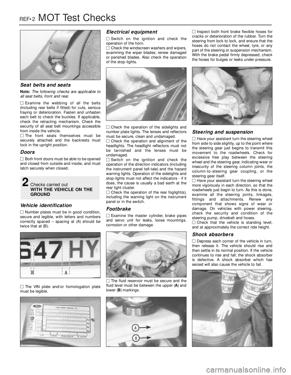
Vehicle identification
MNumber plates must be in good condition,
secure and legible, with letters and numbers
correctly spaced – spacing at (A) should be
twice that at (B).
MThe VIN plate and/or homologation plate
must be legible.
Electrical equipment
MSwitch on the ignition and check the
operation of the horn.
MCheck the windscreen washers and wipers,
examining the wiper blades; renew damaged
or perished blades. Also check the operation
of the stop-lights.
MCheck the operation of the sidelights and
number plate lights. The lenses and reflectors
must be secure, clean and undamaged.
MCheck the operation and alignment of the
headlights. The headlight reflectors must not
be tarnished and the lenses must be
undamaged.
MSwitch on the ignition and check the
operation of the direction indicators (including
the instrument panel tell-tale) and the hazard
warning lights. Operation of the sidelights and
stop-lights must not affect the indicators - if it
does, the cause is usually a bad earth at the
rear light cluster.
MCheck the operation of the rear foglight(s),
including the warning light on the instrument
panel or in the switch.
Footbrake
MExamine the master cylinder, brake pipes
and servo unit for leaks, loose mountings,
corrosion or other damage.
MThe fluid reservoir must be secure and the
fluid level must be between the upper (A) and
lower (B) markings.MInspect both front brake flexible hoses for
cracks or deterioration of the rubber. Turn the
steering from lock to lock, and ensure that the
hoses do not contact the wheel, tyre, or any
part of the steering or suspension mechanism.
With the brake pedal firmly depressed, check
the hoses for bulges or leaks under pressure.
Steering and suspension
MHave your assistant turn the steering wheel
from side to side slightly, up to the point where
the steering gear just begins to transmit this
movement to the roadwheels. Check for
excessive free play between the steering
wheel and the steering gear, indicating wear or
insecurity of the steering column joints, the
column-to-steering gear coupling, or the
steering gear itself.
MHave your assistant turn the steering wheel
more vigorously in each direction, so that the
roadwheels just begin to turn. As this is done,
examine all the steering joints, linkages,
fittings and attachments. Renew any
component that shows signs of wear or
damage. On vehicles with power steering,
check the security and condition of the
steering pump, drivebelt and hoses.
MCheck that the vehicle is standing level,
and at approximately the correct ride height.
Shock absorbers
MDepress each corner of the vehicle in turn,
then release it. The vehicle should rise and
then settle in its normal position. If the vehicle
continues to rise and fall, the shock absorber
is defective. A shock absorber which has
seized will also cause the vehicle to fail.
2Checks carried out
WITH THE VEHICLE ON THE
GROUND
Page 287 of 303

REF•4MOT Test Checks
MExamine the handbrake mechanism,
checking for frayed or broken cables,
excessive corrosion, or wear or insecurity of
the linkage. Check that the mechanism works
on each relevant wheel, and releases fully,
without binding.
MIt is not possible to test brake efficiency
without special equipment, but a road test can
be carried out later to check that the vehicle
pulls up in a straight line.
Fuel and exhaust systems
MInspect the fuel tank (including the filler
cap), fuel pipes, hoses and unions. All
components must be secure and free from
leaks.
MExamine the exhaust system over its entire
length, checking for any damaged, broken or
missing mountings, security of the retaining
clamps and rust or corrosion.
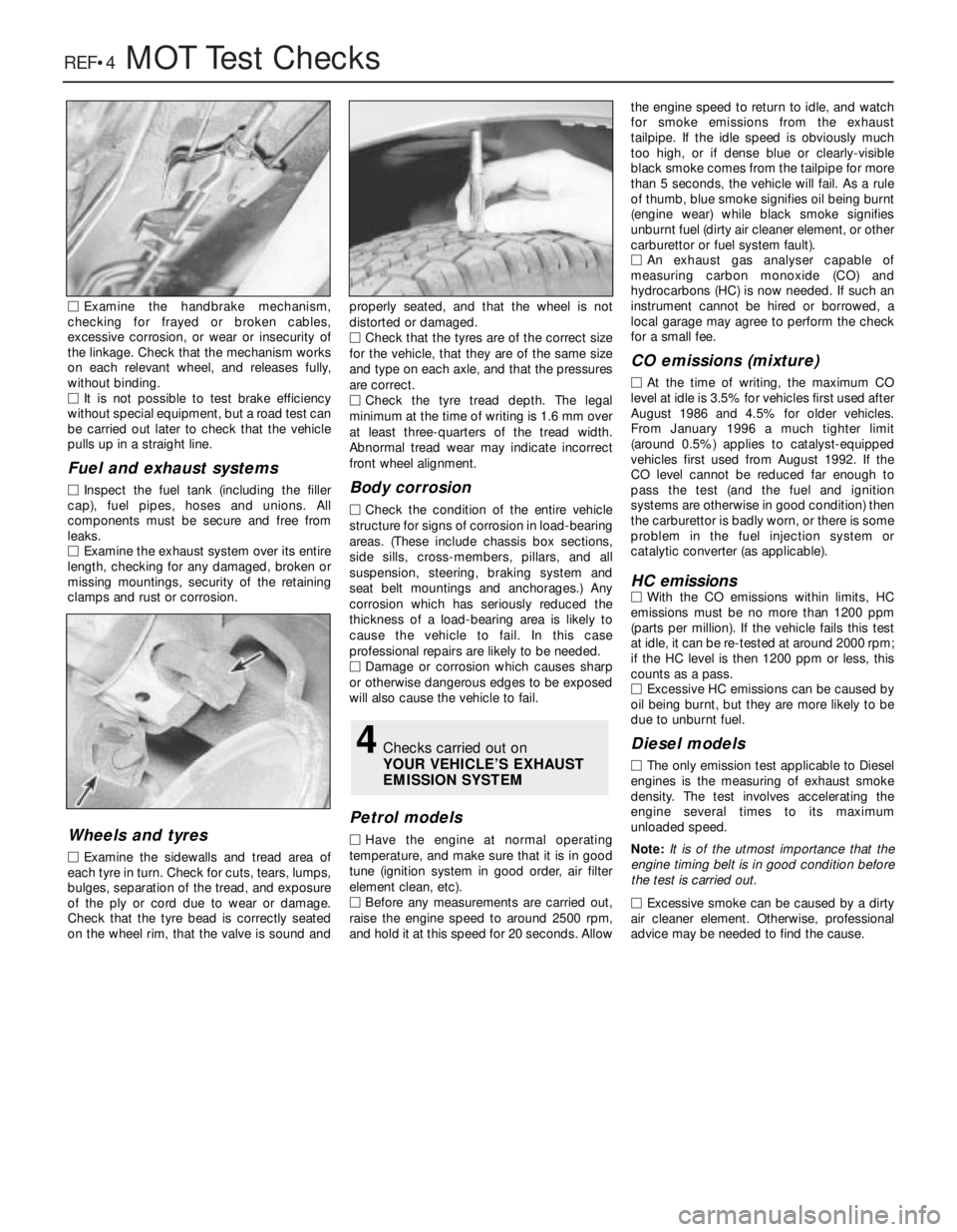
Wheels and tyres
MExamine the sidewalls and tread area of
each tyre in turn. Check for cuts, tears, lumps,
bulges, separation of the tread, and exposure
of the ply or cord due to wear or damage.
Check that the tyre bead is correctly seated
on the wheel rim, that the valve is sound andproperly seated, and that the wheel is not
distorted or damaged.
MCheck that the tyres are of the correct size
for the vehicle, that they are of the same size
and type on each axle, and that the pressures
are correct.
MCheck the tyre tread depth. The legal
minimum at the time of writing is 1.6 mm over
at least three-quarters of the tread width.
Abnormal tread wear may indicate incorrect
front wheel alignment.
Body corrosion
MCheck the condition of the entire vehicle
structure for signs of corrosion in load-bearing
areas. (These include chassis box sections,
side sills, cross-members, pillars, and all
suspension, steering, braking system and
seat belt mountings and anchorages.) Any
corrosion which has seriously reduced the
thickness of a load-bearing area is likely to
cause the vehicle to fail. In this case
professional repairs are likely to be needed.
MDamage or corrosion which causes sharp
or otherwise dangerous edges to be exposed
will also cause the vehicle to fail.
Petrol models
MHave the engine at normal operating
temperature, and make sure that it is in good
tune (ignition system in good order, air filter
element clean, etc).
MBefore any measurements are carried out,
raise the engine speed to around 2500 rpm,
and hold it at this speed for 20 seconds. Allowthe engine speed to return to idle, and watch
for smoke emissions from the exhaust
tailpipe. If the idle speed is obviously much
too high, or if dense blue or clearly-visible
black smoke comes from the tailpipe for more
than 5 seconds, the vehicle will fail. As a rule
of thumb, blue smoke signifies oil being burnt
(engine wear) while black smoke signifies
unburnt fuel (dirty air cleaner element, or other
carburettor or fuel system fault).
MAn exhaust gas analyser capable of
measuring carbon monoxide (CO) and
hydrocarbons (HC) is now needed. If such an
instrument cannot be hired or borrowed, a
local garage may agree to perform the check
for a small fee.
CO emissions (mixture)
MAt the time of writing, the maximum CO
level at idle is 3.5% for vehicles first used after
August 1986 and 4.5% for older vehicles.
From January 1996 a much tighter limit
(around 0.5%) applies to catalyst-equipped
vehicles first used from August 1992. If the
CO level cannot be reduced far enough to
pass the test (and the fuel and ignition
systems are otherwise in good condition) then
the carburettor is badly worn, or there is some
problem in the fuel injection system or
catalytic converter (as applicable).
HC emissionsMWith the CO emissions within limits, HC
emissions must be no more than 1200 ppm
(parts per million). If the vehicle fails this test
at idle, it can be re-tested at around 2000 rpm;
if the HC level is then 1200 ppm or less, this
counts as a pass.
MExcessive HC emissions can be caused by
oil being burnt, but they are more likely to be
due to unburnt fuel.
Diesel models
MThe only emission test applicable to Diesel
engines is the measuring of exhaust smoke
density. The test involves accelerating the
engine several times to its maximum
unloaded speed.
Note: It is of the utmost importance that the
engine timing belt is in good condition before
the test is carried out.
M
Excessive smoke can be caused by a dirty
air cleaner element. Otherwise, professional
advice may be needed to find the cause.
4Checks carried out on
YOUR VEHICLE’S EXHAUST
EMISSION SYSTEM
Page 296 of 303

Glossary of Technical TermsREF•13
REF
A
ABS (Anti-lock brake system)A system,
usually electronically controlled, that senses
incipient wheel lockup during braking and
relieves hydraulic pressure at wheels that are
about to skid.
Air bag An inflatable bag hidden in the
steering wheel (driver’s side) or the dash or
glovebox (passenger side). In a head-on
collision, the bags inflate, preventing the
driver and front passenger from being thrown
forward into the steering wheel or windscreen.
Air cleanerA metal or plastic housing,
containing a filter element, which removes
dust and dirt from the air being drawn into the
engine.
Air filter elementThe actual filter in an air
cleaner system, usually manufactured from
pleated paper and requiring renewal at regular
intervals.
Allen keyA hexagonal wrench which fits into
a recessed hexagonal hole.
Alligator clipA long-nosed spring-loaded
metal clip with meshing teeth. Used to make
temporary electrical connections.
AlternatorA component in the electrical
system which converts mechanical energy
from a drivebelt into electrical energy to
charge the battery and to operate the starting
system, ignition system and electrical
accessories.
Ampere (amp)A unit of measurement for the
flow of electric current. One amp is the
amount of current produced by one volt
acting through a resistance of one ohm.
Anaerobic sealerA substance used to
prevent bolts and screws from loosening.
Anaerobic means that it does not require
oxygen for activation. The Loctite brand is
widely used.
AntifreezeA substance (usually ethylene
glycol) mixed with water, and added to a
vehicle’s cooling system, to prevent freezing
of the coolant in winter. Antifreeze also
contains chemicals to inhibit corrosion and
the formation of rust and other deposits that
would tend to clog the radiator and coolant
passages and reduce cooling efficiency.
Anti-seize compoundA coating that
reduces the risk of seizing on fasteners that
are subjected to high temperatures, such as
exhaust manifold bolts and nuts.
AsbestosA natural fibrous mineral with great
heat resistance, commonly used in the
composition of brake friction materials.Asbestos is a health hazard and the dust
created by brake systems should never be
inhaled or ingested.
AxleA shaft on which a wheel revolves, or
which revolves with a wheel. Also, a solid
beam that connects the two wheels at one
end of the vehicle. An axle which also
transmits power to the wheels is known as a
live axle.
AxleshaftA single rotating shaft, on either
side of the differential, which delivers power
from the final drive assembly to the drive
wheels. Also called a driveshaft or a halfshaft.
BBall bearingAn anti-friction bearing
consisting of a hardened inner and outer race
with hardened steel balls between two races.
BearingThe curved surface on a shaft or in a
bore, or the part assembled into either, that
permits relative motion between them with
minimum wear and friction.
Big-end bearingThe bearing in the end of
the connecting rod that’s attached to the
crankshaft.
Bleed nippleA valve on a brake wheel
cylinder, caliper or other hydraulic component
that is opened to purge the hydraulic system
of air. Also called a bleed screw.
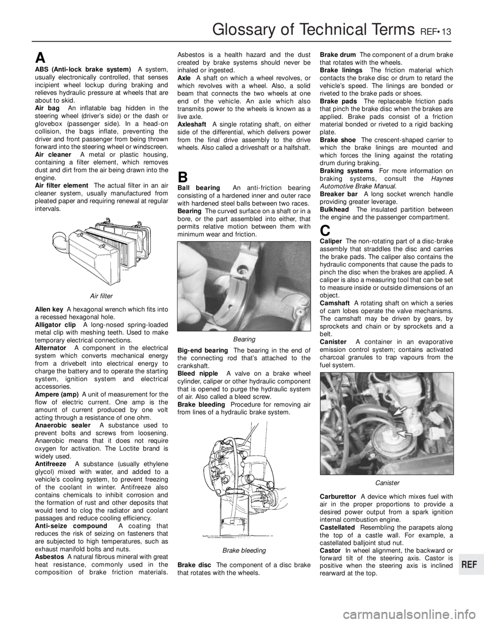
Brake bleedingProcedure for removing air
from lines of a hydraulic brake system.
Brake discThe component of a disc brake
that rotates with the wheels.Brake drumThe component of a drum brake
that rotates with the wheels.
Brake liningsThe friction material which
contacts the brake disc or drum to retard the
vehicle’s speed. The linings are bonded or
riveted to the brake pads or shoes.
Brake padsThe replaceable friction pads
that pinch the brake disc when the brakes are
applied. Brake pads consist of a friction
material bonded or riveted to a rigid backing
plate.
Brake shoeThe crescent-shaped carrier to
which the brake linings are mounted and
which forces the lining against the rotating
drum during braking.
Braking systemsFor more information on
braking systems, consult the Haynes
Automotive Brake Manual.
Breaker barA long socket wrench handle
providing greater leverage.
BulkheadThe insulated partition between
the engine and the passenger compartment.
CCaliperThe non-rotating part of a disc-brake
assembly that straddles the disc and carries
the brake pads. The caliper also contains the
hydraulic components that cause the pads to
pinch the disc when the brakes are applied. A
caliper is also a measuring tool that can be set
to measure inside or outside dimensions of an
object.
CamshaftA rotating shaft on which a series
of cam lobes operate the valve mechanisms.
The camshaft may be driven by gears, by
sprockets and chain or by sprockets and a
belt.
CanisterA container in an evaporative
emission control system; contains activated
charcoal granules to trap vapours from the
fuel system.
CarburettorA device which mixes fuel with
air in the proper proportions to provide a
desired power output from a spark ignition
internal combustion engine.
CastellatedResembling the parapets along
the top of a castle wall. For example, a
castellated balljoint stud nut.
CastorIn wheel alignment, the backward or
forward tilt of the steering axis. Castor is
positive when the steering axis is inclined
rearward at the top.
Canister
Brake bleeding
Bearing
Air filter
Page 302 of 303

S
Safety first -0•5
Safety pressure switch - 13•90
Scalding -0•5
Scratches in bodywork - 12•2
Screw threads and fastenings - REF•8
Seat belts - 12•10, REF•2
Seats - 12•9, REF•2
Servo unit -8•8, 13•103
Shock absorbers - 11•4, REF•2, REF•3
Shoes -8•3
Side light -9•7
Side repeater lamp -9•7
Spares - REF•10, REF•12
Spark plugs -4•7, 13•92
Speedometer -9•8
Spotlamp - 13•108
Springs - 11•3, 11•4, REF•3
Starter motor -9•4, 13•104, 13•105
Starter fault -1•35, 9•14, 13•92, REF•10
Steering-9•5, 10•1et seq, 13•106, REF•1,
REF•2, REF•3
Steering fault finding - 10•4
Stop lamp switch -8•9
Struts - 11•2, 13•111
Sump -1•11, 1•22, 1•26, 1•31, 13•19,
13•24, 13•46, 13•53
Sunroof - 12•12
Supplement: Revisions and information on
later models- 13•1et seq
Supplementary air valve - 13•67, 13•69,
13•71, 13•80
Suspension- 11•1et seq, 13•111, REF•2,
REF•3
Suspension fault finding - 11•6
Switches -2•3, 4•8, 8•9, 9•5, 13•69, 13•72,
13•80, 13•90, 13•106 to 13•109
T
Tailgate -9•6, 12•8, 12•9, 13•112
TDC sensor -4•7, 13•90, 13•91
Thermostat -2•3, 13•54, 13•57
Throttle control linkage - 13•72
Throttle position switch - 13•69, 13•72,
13•80
Throttle valve housing - 13•67, 13•70,
13•80
Tie-rod - 10•2
Timing -4•4, 13•85, 13•91
Timing belt -1•24, 1•29, 1•32, 13•20,
13•30, 13•35, 13•38, 13•53
Timing chain -1•9, 1•19, 1•22
Tools - REF•5, REF•7, REF•8, REF•10
Towing -0•8
Track control arm - 11•4
Trailing arms - 11•5
Transmission-1•13, 1•22, 1•27, 1•32, 6•1
et seq, 13•26, 13•33, 13•36, 13•49,
13•53, 13•94, 13•96
Transmission fault finding -6•4
Transmission oil -0•6, 0•13, 6•1, 13•14,
13•95
Trim panels - 12•5, 13•114
Trip master - 13•108
Tripode joint -7•3
Turbocharger - 13•82, 13•83
Turbocharger fault finding - 13•84
Tyres -7•5, 10•4, 11•6, REF•4
U
Underframe - 12•1
Unleaded fuel - 13•60
Upholstery - 12•2
V
Vacuum sensor - 13•86
Vacuum servo -8•8, 13•103
Valve clearances -1•9, 1•23, 1•32, 13•20,
13•37
Vehicle identification - REF•2, REF•12
Voltage regulator -9•4
W
Washer system -9•10, 13•110
Water pump -2•4, 13•55, 13•58
Weights -0•6, 13•17
Wheel alignment - 10•3
Wheel bearings -7•3, 7•4, REF•3
Wheel changing -0•8
Wheel cylinder -8•4
Wheels -7•5, REF•4
Window regulator - 12•7
Windows -9•11, 12•6, 12•9, 13•109,
13•113
Windscreen - 12•8, REF•1
Wings - 12•5
Wiper blade and arm -9•9
Wiper motor -9•9, 9•10, 13•109, 13•110
Wiper fault -9•14
Wiring diagrams- 14•1et seq
Working facilities - REF•7
IndexREF•19
REF