1983 FIAT UNO window
[x] Cancel search: windowPage 115 of 303
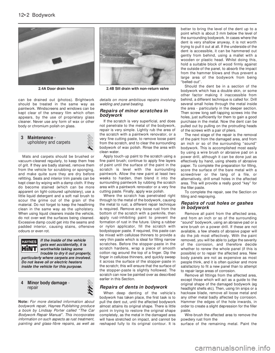
can be drained out (photos). Brightwork
should be treated in the same way as
paintwork. Windscreens and windows can be
kept clear of the smeary film which often
appears, by the use of proprietary glass
cleaner. Never use any form of wax or other
body or chromium polish on glass.
3 Maintenance-
upholstery and carpets
1
Mats and carpets should be brushed or
vacuum-cleaned regularly, to keep them free
of grit. If they are badly stained, remove them
from the vehicle for scrubbing or sponging,
and make quite sure they are dry before
refitting. Seats and interior trim panels can be
kept clean by wiping with a damp cloth. If they
do become stained (which can be more
apparent on light-coloured upholstery), use a
little liquid detergent and a soft nail brush to
scour the grime out of the grain of the
material. Do not forget to keep the headlining
clean in the same way as the upholstery.
When using liquid cleaners inside the vehicle,
do not over-wet the surfaces being cleaned.
Excessive damp could get into the seams and
padded interior, causing stains, offensive
odours or even rot.
4 Minor body damage-
repair
3
Note:For more detailed information about
bodywork repair, Haynes Publishing produce
a book by Lindsay Porter called “The Car
Bodywork Repair Manual”. This incorporates
information on such aspects as rust treatment,
painting and glass-fibre repairs, as well asdetails on more ambitious repairs involving
welding and panel beating.
Repairs of minor scratches in
bodywork
If the scratch is very superficial, and does
not penetrate to the metal of the bodywork,
repair is very simple. Lightly rub the area of
the scratch with a paintwork renovator, or a
very fine cutting paste, to remove loose paint
from the scratch, and to clear the surrounding
bodywork of wax polish. Rinse the area with
clean water.
Apply touch-up paint to the scratch using a
fine paint brush; continue to apply fine layers
of paint until the surface of the paint in the
scratch is level with the surrounding
paintwork. Allow the new paint at least two
weeks to harden, then blend it into the
surrounding paintwork by rubbing the scratch
area with a paintwork renovator or a very fine
cutting paste. Finally, apply wax polish.
Where the scratch has penetrated right
through to the metal of the bodywork, causing
the metal to rust, a different repair technique
is required. Remove any loose rust from the
bottom of the scratch with a penknife, then
apply rust-inhibiting paint to prevent the
formation of rust in the future. Using a rubber
or nylon applicator, fill the scratch with
bodystopper paste. If required, this paste can
be mixed with cellulose thinners to provide a
very thin paste which is ideal for filling narrow
scratches. Before the stopper-paste in the
scratch hardens, wrap a piece of smooth
cotton rag around the top of a finger. Dip the
finger in cellulose thinners, and quickly sweep
it across the surface of the stopper-paste in
the scratch; this will ensure that the surface of
the stopper-paste is slightly hollowed. The
scratch can now be painted over as described
earlier in this Section.
Repairs of dents in bodywork
When deep denting of the vehicle’s
bodywork has taken place, the first task is to
pull the dent out, until the affected bodywork
almost attains its original shape. There is little
point in trying to restore the original shape
completely, as the metal in the damaged area
will have stretched on impact, and cannot be
reshaped fully to its original contour. It isbetter to bring the level of the dent up to a
point which is about 3 mm below the level of
the surrounding bodywork. In cases where the
dent is very shallow anyway, it is not worth
trying to pull it out at all. If the underside of the
dent is accessible, it can be hammered out
gently from behind, using a mallet with a
wooden or plastic head. Whilst doing this,
hold a suitable block of wood firmly against
the outside of the panel, to absorb the impact
from the hammer blows and thus prevent a
large area of the bodywork from being
“belled-out”.
Should the dent be in a section of the
bodywork which has a double skin, or some
other factor making it inaccessible from
behind, a different technique is called for. Drill
several small holes through the metal inside
the area - particularly in the deeper section.
Then screw long self-tapping screws into the
holes, just sufficiently for them to gain a good
purchase in the metal. Now the dent can be
pulled out by pulling on the protruding heads
of the screws with a pair of pliers.
The next stage of the repair is the removal
of the paint from the damaged area, and from
an inch or so of the surrounding “sound”
bodywork. This is accomplished most easily
by using a wire brush or abrasive pad on a
power drill, although it can be done just as
effectively by hand, using sheets of abrasive
paper. To complete the preparation for filling,
score the surface of the bare metal with a
screwdriver or the tang of a file, or
alternatively, drill small holes in the affected
area. This will provide a really good “key” for
the filler paste.
To complete the repair, see the Section on
filling and respraying.
Repairs of rust holes or gashes
in bodywork
Remove all paint from the affected area,
and from an inch or so of the surrounding
“sound” bodywork, using an abrasive pad or a
wire brush on a power drill. If these are not
available, a few sheets of abrasive paper will
do the job most effectively. With the paint
removed, you will be able to judge the severity
of the corrosion, and therefore decide
whether to renew the whole panel (if this is
possible) or to repair the affected area. New
body panels are not as expensive as most
people think, and it is often quicker and more
satisfactory to fit a new panel than to attempt
to repair large areas of corrosion.
Remove all fittings from the affected area,
except those which will act as a guide to the
original shape of the damaged bodywork (eg
headlight shells etc). Then, using tin snips or a
hacksaw blade, remove all loose metal and
any other metal badly affected by corrosion.
Hammer the edges of the hole inwards, in
order to create a slight depression for the filler
paste.
Wire-brush the affected area to remove the
powdery rust from the
surface of the remaining metal. Paint the
12•2 Bodywork
2.4B Sill drain with non-return valve2.4A Door drain hole
If the inside of the vehicle
gets wet accidentally, it is
worthwhile taking some
trouble to dry it out properly,
particularly where carpets are involved.
Do not leave oil or electric heaters
inside the vehicle for this purpose.
Page 118 of 303
10 Front wing-
removal and refitting
1
1Remove the headlamp and front parking
lamp as described in Chapter 9. 2Withdraw the side repeater lamp and
disconnect the leads.
3Remove the front roadwheel.
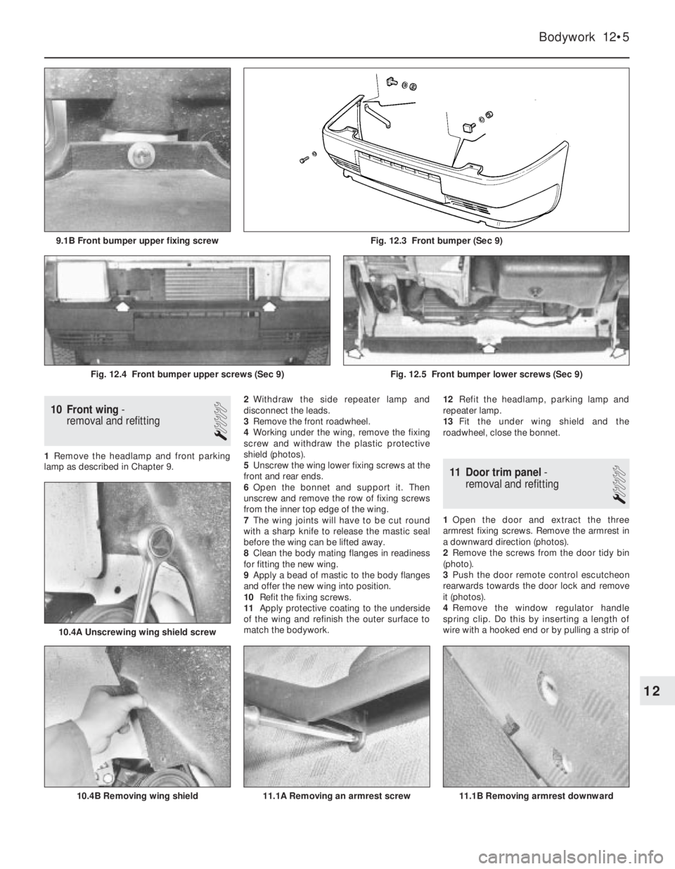
4Working under the wing, remove the fixing
screw and withdraw the plastic protective
shield (photos).
5Unscrew the wing lower fixing screws at the
front and rear ends.
6Open the bonnet and support it. Then
unscrew and remove the row of fixing screws
from the inner top edge of the wing.
7The wing joints will have to be cut round
with a sharp knife to release the mastic seal
before the wing can be lifted away.
8Clean the body mating flanges in readiness
for fitting the new wing.
9Apply a bead of mastic to the body flanges
and offer the new wing into position.
10Refit the fixing screws.
11Apply protective coating to the underside
of the wing and refinish the outer surface to
match the bodywork. 12Refit the headlamp, parking lamp and
repeater lamp.
13Fit the under wing shield and the
roadwheel, close the bonnet.
11 Door trim panel-
removal and refitting
1
1Open the door and extract the three
armrest fixing screws. Remove the armrest in
a downward direction (photos).
2Remove the screws from the door tidy bin
(photo).
3Push the door remote control escutcheon
rearwards towards the door lock and remove
it (photos).
4Remove the window regulator handle
spring clip. Do this by inserting a length of
wire with a hooked end or by pulling a strip of
Bodywork 12•5
Fig. 12.3 Front bumper (Sec 9)9.1B Front bumper upper fixing screw
11.1B Removing armrest downward11.1A Removing an armrest screw
10.4A Unscrewing wing shield screw
10.4B Removing wing shield
Fig. 12.4 Front bumper upper screws (Sec 9)Fig. 12.5 Front bumper lower screws (Sec 9)
12
Page 119 of 303
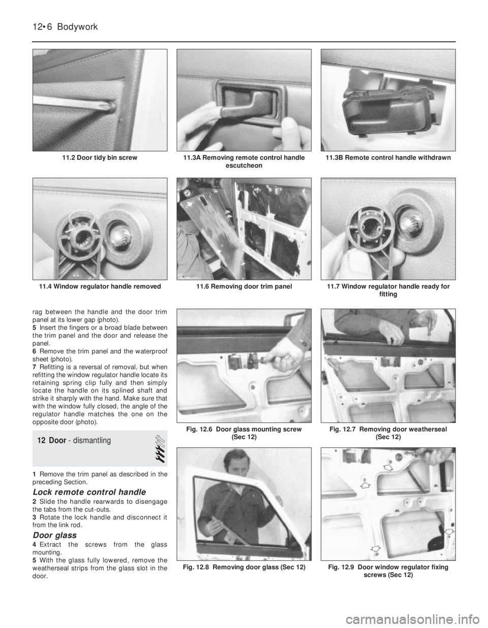
rag between the handle and the door trim
panel at its lower gap (photo).
5Insert the fingers or a broad blade between
the trim panel and the door and release the
panel.
6Remove the trim panel and the waterproof
sheet (photo).
7Refitting is a reversal of removal, but when
refitting the window regulator handle locate its
retaining spring clip fully and then simply
locate the handle on its splined shaft and
strike it sharply with the hand. Make sure that
with the window fully closed, the angle of the
regulator handle matches the one on the
opposite door (photo).
12 Door- dismantling
3
1Remove the trim panel as described in the
preceding Section.
Lock remote control handle
2Slide the handle rearwards to disengage
the tabs from the cut-outs.
3Rotate the lock handle and disconnect it
from the link rod.
Door glass
4Extract the screws from the glass
mounting.
5With the glass fully lowered, remove the
weatherseal strips from the glass slot in the
door.
Fig. 12.9 Door window regulator fixing
screws (Sec 12)Fig. 12.8 Removing door glass (Sec 12)
Fig. 12.7 Removing door weatherseal
(Sec 12)Fig. 12.6 Door glass mounting screw
(Sec 12)
12•6 Bodywork
11.7 Window regulator handle ready for
fitting11.6 Removing door trim panel11.4 Window regulator handle removed
11.3B Remote control handle withdrawn11.3A Removing remote control handle
escutcheon11.2 Door tidy bin screw
Page 120 of 303
6Turn the glass very carefully and withdraw it
from the door. A new glass is supplied
complete with lower mounting.
Window regulator
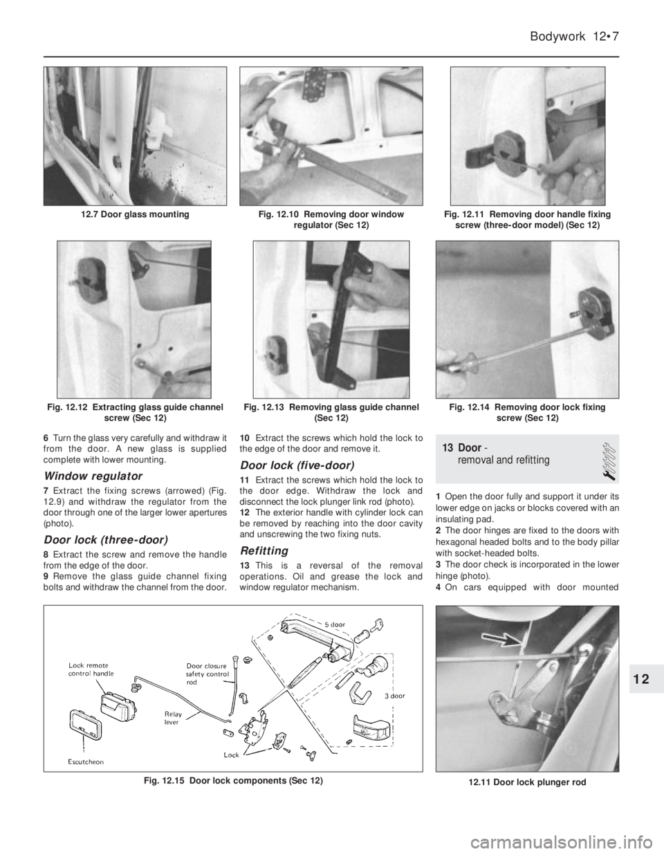
7Extract the fixing screws (arrowed) (Fig.
12.9) and withdraw the regulator from the
door through one of the larger lower apertures
(photo).
Door lock (three-door)
8Extract the screw and remove the handle
from the edge of the door.
9Remove the glass guide channel fixing
bolts and withdraw the channel from the door. 10Extract the screws which hold the lock to
the edge of the door and remove it.
Door lock (five-door)
11Extract the screws which hold the lock to
the door edge. Withdraw the lock and
disconnect the lock plunger link rod (photo).
12The exterior handle with cylinder lock can
be removed by reaching into the door cavity
and unscrewing the two fixing nuts.
Refitting
13This is a reversal of the removal
operations. Oil and grease the lock and
window regulator mechanism.
13 Door-
removal and refitting
1
1Open the door fully and support it under its
lower edge on jacks or blocks covered with an
insulating pad.
2The door hinges are fixed to the doors with
hexagonal headed bolts and to the body pillar
with socket-headed bolts.
3The door check is incorporated in the lower
hinge (photo).
4On cars equipped with door mounted
Bodywork 12•7
Fig. 12.11 Removing door handle fixing
screw (three-door model) (Sec 12)Fig. 12.10 Removing door window
regulator (Sec 12)12.7 Door glass mounting
Fig. 12.14 Removing door lock fixing
screw (Sec 12)Fig. 12.13 Removing glass guide channel
(Sec 12)Fig. 12.12 Extracting glass guide channel
screw (Sec 12)
12
Fig. 12.15 Door lock components (Sec 12)12.11 Door lock plunger rod
Page 121 of 303
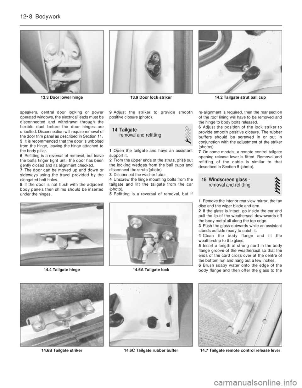
speakers, central door locking or power
operated windows, the electrical leads must be
disconnected and withdrawn through the
flexible duct before the door hinges are
unbolted. Disconnection will require removal of
the door trim panel as described in Section 11.
5It is recommended that the door is unbolted
from the hinge, leaving the hinge attached to
the body pillar.
6Refitting is a reversal of removal, but leave
the bolts finger tight until the door has been
gently closed and its alignment checked.
7The door can be moved up and down or
sideways using the travel provided by the
elongated bolt holes.
8If the door is not flush with the adjacent
body panels then shims should be inserted
under the hinges.9Adjust the striker to provide smooth
positive closure (photo).
14 Tailgate-
removal and refitting
1
1Open the tailgate and have an assistant
support it.
2From the upper ends of the struts, prise out
the locking wedges from the ball cups and
disconnect the struts (photo).
3Disconnect the washer tube.
4Unscrew the hinge mounting bolts from the
tailgate and lift the tailgate from the car
(photo).
5Refitting is a reversal of removal, but ifre-alignment is required, then the rear section
of the roof lining will have to be removed and
the hinge to body bolts released.
6Adjust the position of the lock striker to
provide smooth positive closure. The rubber
buffers should be screwed in or out in
conjunction with the adjustment of the striker
(photos).
7On some models, a remote control tailgate
opening release lever is fitted. Removal and
refitting of the cable is similar to that
described in Section 8 (photo).
15 Windscreen glass-
removal and refitting
5
1Remove the interior rear view mirror, the tax
disc and the wiper blade and arm.
2If the glass is intact, go inside the car and
pull the lip of the weatherseal downwards off
the body metal all along the top edge.
3Push the glass outwards while an assistant
stands outside ready to catch it.
4Clean the body flange and fit the
weatherstrip to the glass.
5Insert a length of strong cord in the body
flange groove of the weatherseal so that the
ends of the cord cross over at the centre of
the bottom run and hang out a few inches.
6Brush soapy water onto the edge of the
body flange and then offer the glass to the
12•8 Bodywork
14.7 Tailgate remote control release lever14.6C Tailgate rubber buffer14.6B Tailgate striker
14.6A Tailgate lock14.4 Tailgate hinge
14.2 Tailgate strut ball cup13.9 Door lock striker13.3 Door lower hinge
Page 122 of 303

body so that the bottom edge of the rubber
seal engages over the metal flange.
7With an assistant pressing on the outside of
the glass, go inside and pull the cords evenly.
This will draw the lip of the weatherseal over
the body flange and seat the glass.
8Tap the glass with the palm of the hand to
settle it.
9If the weatherseal is in good condition then
it should prove waterproof, but if there is any
doubt, apply sealant with a gun between the
rubber and the glass and the rubber and the
body flange.
10Refit the mirror, tax disc and wiper.
16 Tailgate glass-
removal and refitting
5
1The operations are very similar to those
described for the windscreen, but disconnect
the leads from the heater element terminals.
17 Fixed side window
(five-door)-
removal and refitting
5
1The operations are similar to those
described for the windscreen in Section 15.
18 Opening side window
(three-door)-
removal and refitting
1
1Have an assistant support the glass and
then extract the screws from the hinges and
the toggle type fastener.
2Swivel the glass outwards and downwards
to remove it.
3Refitting is a reversal of removal.
19 Front seat-
removal and refitting
1
1Unbolt the seat front anchorage clamps
(photo).
2Slide the seat fully rearwards out of its
guide rails, but bend the end of the seatadjustment lever so that it passes over its
stop.
20 Rear seat-
removal and refitting
1
1The rear seat may be of one piece design or
split (60/40) depending upon the model.
2Either type of seat is easily removable once
the hinge bolts have been unscrewed and
removed (photo).
21 Centre console-
removal and refitting
1
1Pull the small black knobs from the heater
control levers.
2Extract the screws from both sides of the
heater control panel, remove the panel. As the
panel is withdrawn, disconnect the leads from
the cigar lighter and take care not to damage
the fibre optics.
3From inside the glove box, prise out the lid
stop block. Insert a screwdriver in the hole left
by its removal and unscrew the console fixing
screw (photo).
Bodywork 12•9
Fig. 12.18 Components of opening side window (Sec 18)
Fig. 12.17 Position of cord for fitting
windscreen weatherseal (Sec 15)
Fig. 12.16 Peeling back lip of windscreen
glass weatherseal (Sec 15)
21.3 Removing screw (glovebox side) from
centre console20.2 Rear seat mounting hinges19.1 Front seat mounting clamp
12
Page 124 of 303
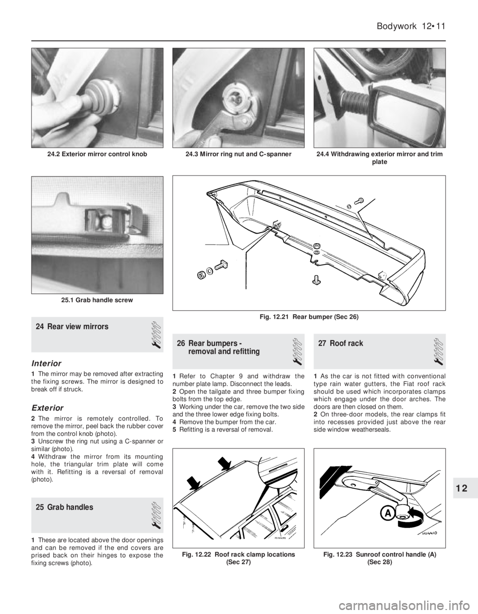
24 Rear view mirrors
1
Interior
1The mirror may be removed after extracting
the fixing screws. The mirror is designed to
break off if struck.
Exterior
2The mirror is remotely controlled. To
remove the mirror, peel back the rubber cover
from the control knob (photo).
3Unscrew the ring nut using a C-spanner or
similar (photo).
4Withdraw the mirror from its mounting
hole, the triangular trim plate will come
with it. Refitting is a reversal of removal
(photo).
25 Grab handles
1
1These are located above the door openings
and can be removed if the end covers are
prised back on their hinges to expose the
fixing screws (photo).
26 Rear bumpers -
removal and refitting
1
1Refer to Chapter 9 and withdraw the
number plate lamp. Disconnect the leads.
2Open the tailgate and three bumper fixing
bolts from the top edge.
3Working under the car, remove the two side
and the three lower edge fixing bolts.
4Remove the bumper from the car.
5Refitting is a reversal of removal.
27 Roof rack
1
1As the car is not fitted with conventional
type rain water gutters, the Fiat roof rack
should be used which incorporates clamps
which engage under the door arches. The
doors are then closed on them.
2On three-door models, the rear clamps fit
into recesses provided just above the rear
side window weatherseals.
Bodywork 12•11
24.4 Withdrawing exterior mirror and trim
plate
25.1 Grab handle screw
24.3 Mirror ring nut and C-spanner24.2 Exterior mirror control knob
Fig. 12.23 Sunroof control handle (A)
(Sec 28)Fig. 12.22 Roof rack clamp locations
(Sec 27)
Fig. 12.21 Rear bumper (Sec 26)
12
Page 128 of 303

Braking system................................................................................. 14
Part A: Braking system general
Front brake pads all later models
Part B: Braking system - Turbo ie models
Description
Front disc pads - renewal
Front disc caliper - removal and refitting
Front disc caliper - overhaul
Front brake disc - inspection, renovation or renewal
Rear disc pads - renewal
Rear disc caliper - removal, overhaul and refitting
Rear brake disc - inspection, renovation and renewal
Pressure regulating valve
Brake pedal - removal and refitting
Vacuum servo unit and master cylinder - general
Antiskid system - description
Electrical system.............................................................................. 15
Alternator (999 cc models) - removal and refitting
Alternator (later models) - removal and refitting
Alternator brushes - renewal
Starter motor (999 cc models) - removal and refitting
Starter motor (1301 cc Turbo ie, 1372 cc ie, 1372 cc Turbo ie)
- removal and refitting
Starter motor brushes (later models) - renewal
Fuses - later models
Relays (Turbo ie models) - general
Headlamps - later models
Headlamp beam adjusters for load compensation - later models
Headlamp unit removal - later models
Headlamp dim-dip system - description
Front fog lamps bulb/unit - removal and refitting and beam
adjustment
Horn - relocation
Steering column combination switches (later models) - removal
and refittingInstrument panel (Turbo ie models) - removal and refitting
Facia-mounted switches (1301 cc Turbo ie model) - removal
and refitting
Instrument panel (later models) - removal and refitting
Auxiliary control panel (later models) - removal and refitting
Heater control panel (later models) - removal and refitting
Trip master
Interior roof mounted spotlamp, switch and/or clock - removal
and refitting
Central door locking system
Cigar lighter (later models) - removal and refitting
Electrically operated window switches - removal and refitting
Windscreen wiper motor (later models) - removal and refitting
Windscreen washer reservoir (Turbo) - removal and refitting
Tailgate wiper motor (later models) - removal and refitting
Radio Check control system sensors - description
Check control system sensors - testing
Suspension....................................................................................... 16
Front anti-roll bar - removal and refitting
Suspension strut later models
Bodywork.......................................................................................... 17
Plastic components
Rear view mirrors
Door armrest
Tailgate (Turbo ie model) - component removal and refitting
Radiator grille (1301 cc Turbo ie model) - removal and
refitting
Radiator grille (1372 cc ie and 1372 cc Turbo ie models) -
removal and refitting
Bumpers (1301 cc Turbo ie, 1372 cc ie and 1372 cc Turbo ie
models) - removal and refitting
Rear hinged windows - removal and refitting
Door trim panel (Turbo ie model) - removal and refitting
Supplement: Revisions and information on later models 13•3
13
1 Introduction
Since its introduction in 1983, the FIAT Uno
has had a number of modifications and
improvements including the fitting of a twin
choke carburettor, low profile tyres, tinted
windows and remotely-controlled central door
locking.
The major mechanical change was the
introduction of the FIRE (Fully Integrated
Robotised Engine) on 45 and 45S models to
be followed by a new 1108 cc “FIRE” engine
on the 60S model from 1989 on.
A 1301 cc Turbo ie engine model wasavailable for a short period. This model had a
Bosch LE2 Jetronic electronic fuel injection
(ie) and a turbocharger to give added
performance. To uprate the braking to suit,
disc brakes were fitted to the rear in place of
the original drum type brakes.
A 1372 cc engine model was introduced in
1989. Two versions were initially available. A
Bosch Mono-Jetronic single-point fuel
injection (SPi) system, as found on the 70 SX
model and Bosch L3.1 or L3.2 Jetronic
multi-point fuel injection (MPi) systems were
fitted to Turbo models. L3.2 MPi system
models were equipped with catalytic
converters, to improve exhaust emission. All
fuel injection engines are fitted with electroni-
cally controlled engine management systems.
A new style instrument panel, switchgearand a revised facia layout was introduced in
1989.
During 1992, SPi fuel systems were fitted to
the 999 cc and 1108 cc engines, along with
catalytic converters for improved exhaust
emissions.
Five speed transmissions were introduced
to 999 cc models in 1993.
It is recommended that this Supplement is
always referred to before the main Chapters
of the Manual.
Project vehicles
The vehicles used in the preparation of this
supplement, and appearing in many of the
photographic sequences were a 1986 Uno
45S FIRE, a 1988 1301 cc Uno Turbo ie and a
1991 1372 cc Uno SXie.
Easy,suitable for
novice with little
experienceFairly easy,suitable
for beginner with
some experienceFairly difficult,
suitable for competent
DIY mechanic
Difficult,suitable for
experienced DIY
mechanicVery difficult,
suitable for expert DIY
or professional
Degrees of difficulty
54321