1982 VOLVO 700 torque
[x] Cancel search: torquePage 15 of 168
(
70019401960 Specifications
Section 1 Service and maintenance
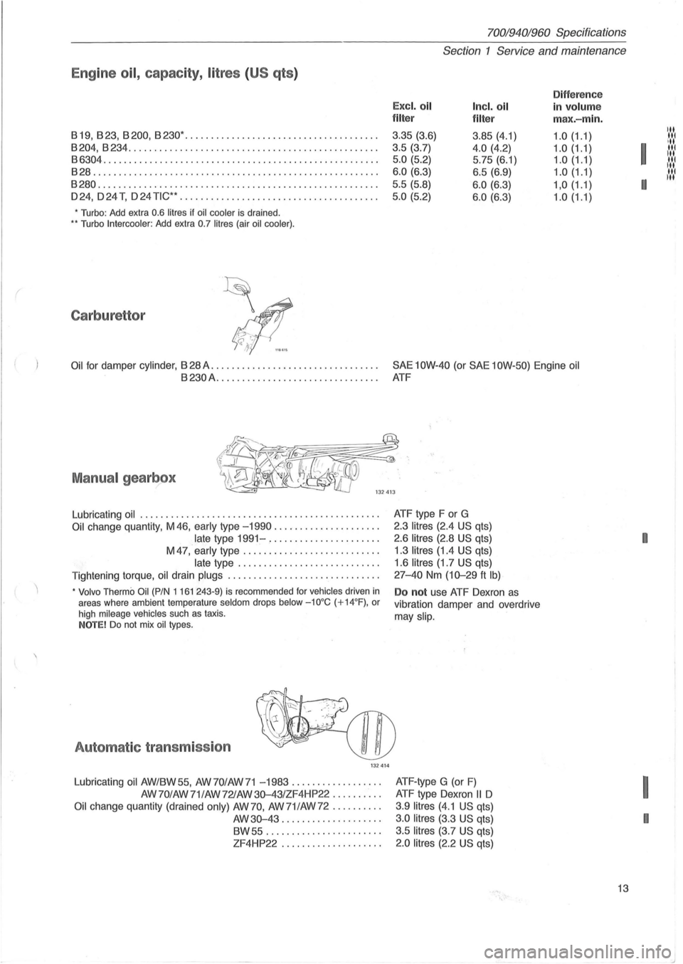
Engine oil, capacity, litres (US qts )
Difference
Excl. oil Incl. oil in volum e filter
filter max.-min.
819,823,8200,8230· .................. ................... .
3.35 (3.6)
3.85 (4.1) 1.0(1.1)
8204,8234 ............................ .................... . 3.5 (3.7) 4.0 (4.2) 1.0 (1.1) 86304 ............................................. ........ . 5.0 (5.2) 5.75 (6.1) 1.0 (1.1)
828 ....................................................... . 6 .0 (6 .3) 6.5 (6.9) 1.0 (1.1)
8280 .......................... ............................ . 5.5 (5.8) 6.0 (6.3) 1,0(1.1)
024,024 T, 024 TiC·· ....................... ............... . 5 .0 (5.2) 6 .0 (6.3) 1.0(1.1)
• Turbo: Add extra 0.6 litres if oil cooler is drained . .. Turbo Intercooler : Add extra 0.7 litres (air oil cooler) .
Carburettor
Oil for damper cylinder , 828 A. . . . . . . . . . . . . . . . . . . . . . . . . . . . . . . . . SAE 10W-40 (or SAE 10W-50) Engine oil
8230A................................ ATF
Manual gearbox
Lubricating oil ............................ .................. .
Oil change quantity, M 46, early type -1990 .................... .
late type 1991-..................... .
M
47, early type ...................... . ... .
late type ........................... .
Tightening torque, oil drain
plugs ............................. .
• Volvo Thermo Oil (PIN 1 161 243-9) is recommended for vehicles driven in areas where ambient temperature seldom drops below -10°C (+14°F) , or
high mileage vehicles such as taxis . NOTE! Do not mix oil types .
Automat ic transmission
132414
Lubricating oil AW/8W55, AW70/AW71 -1983 ................. .
AW70/AW 71/AW721AW
30-43/ZF4HP22 ......... .
Oil change quantity (drained only) AW 70, AW 71 lAW 72 ......... .
AW30-43 ................... .
8W55 ............ .......... .
ZF4HP22 ................... . ATF
type F or G
2.3
litres (2.4 US qts)
2.6
litres (2.8 US qts)
1 .3
litres (1.4 US qts)
1.6
litres (1.7 US qts)
27-40 Nm (10-29 ft Ib)
Do not use ATF Oexron as
vibration damper and overdrive
may
slip.
ATF -type G (or F)
ATF type Oexron II 0
3.9 litres (4.1 US qts)
3 .0 litres (3.3 US qts)
3.5
litres (3.7 US qts)
2.0 litres (2.2 US qts)
13
Itt liN
I
III
:1:1:1
I
11.'.1
I
I
I
Page 17 of 168
70019401960 Specifications
Section 2 B 19, B 23 Engines
Section 2 B 19, B 23 Engines
Group 20 General ................................ 15
Group
21 Engine assembly ........................ 16
Group 22 Lubricating system
....................... 20
Group 23 Fuel system ............................ 21
Group 25 Intake and exhaust systems .............. 31
Group 26 Cooling system .......................... 32
Group 28
Ignition system .......................... 33
j'"
I.t
Group 20 General ~ :,
129750
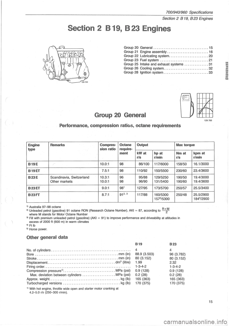
Performance , compression ratios, octane requirements
Engine Remarks Compres-Octane
Output Max torque
type sion
ratio r
equire-
ment
kWat hp at
r/s r/min
819E 10.0:1 98 86/100
117/6000
819ET 7.5:1 98 110/92
150/5500
823E Scandinavia, Switzerland 10.3:1 96 95/88 129/5250
Other markets 10.0:1 98 96/90 131/5400
823ET 9.0:1 981 127/95 173/5700
823FT 8.7:1 912
• 3 117/88 160/5300
1575/5300
1) Australia 97-98 octane 2) Unleaded
petrol (gasoline) 91 octane RON (Research Octane Number). AKI = 87, according to R+2M where M stands for Motor Octane Number
. "
Nm at
r/s
158/50
230/60 190/50
190/60
250/57
250148
3) Fill with premium unleaded petrol (gasoline) (AKI = 91) to improve performance and driveability at altitudes in excess of 2000 It (600 m) in warm climates 4) Ft Ib 5) Horse power.
Other general data
No. of cylinders ............................................. .
Bore .
............................................. .. mm (in)
Stroke ..
.... ......................................... mm (in)
Displacement. ...................................... dm3 (litre)
Firing order ................................................. .
Compression pressure1) ..
............................ MPa (psi)
Max . deviation between
cylinders ................... MPa (psi)
Approx. weight.
............... ........... ..... ......... kg (Ib)
Turbocharged versions ................................. kg (Ib)
1) With hot engine, throttle wide open and starter motor cranking at 4.2-5.0 rls (250-300 r/min).
819
4
88.9
(3.503)
80 (3.152)
1.99
1-3-4-2
0.9 (128)
0 .2 (28)
165 (363)
170 (375)
823
4
96 (3.782)
80 (3.152)
2.32 1-3-4-2
0 .9 (128)
0 .2 (28)
165 (363)
170 (375)
kpm at
r/min
16.1/3000
23.4/3600
19.4/3000
19.4/3600
25.5/3400
25.5/2900 184
4/2900
15
Page 22 of 168
70019401960 Specifications
Section 2 B
19, B 23 Engines
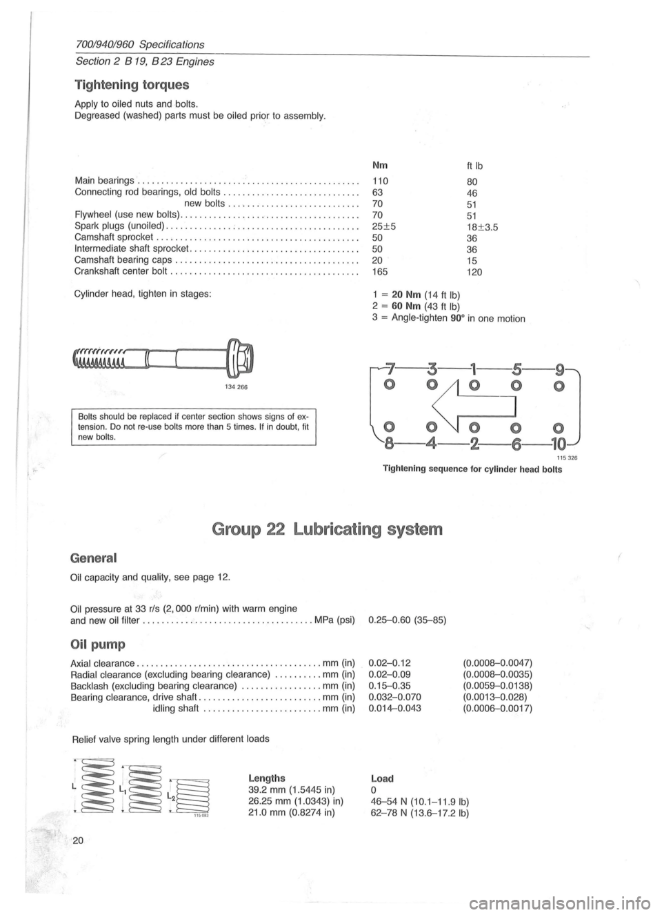
Tightening torques
Apply to oiled nuts and bolts.
Oegreased (washed) parts must be oiled prior to assembly.
Main bearings ....................... ' ....................... .
Connecting rod bearings,
old bolts ............................ .
new
bolts ......... .................. .
Flywheel (use new bolts) ..................................... .
Spark
plugs (unoiled) .............. ; ......................... .
Camshaft sprocket
............... ........................... .
Intermediate shaft sprocket ................................. .. .
Camshaft bearing caps .
............................ ......... .
Crankshaft center
bolt ....................................... .
Cylinder head , tighten in stages:
134266
Bolts should be replaced if center section shows signs of extension. Do not re-use bolts more than 5 times . If in doubt, fit
new bolts.
Nm
110
63
70
70
25±5
50
50 20
165
1 = 20 Nm (14 ft Ib)
2 = 60 Nm (43 ft Ib)
ft Ib
80
46
51
51
18±3.5
36
36 15
120
3 = Angle-tighten 900 in one motion
'7--3---
o 0
000
8-4-2-
--9
o
115326
Tightening sequence for cylinder head bolts
Group 22 Lubricating system
General
Oil capacity and quality, see page 12.
Oil pressure at 33 rls (2,000 r/min) with warm engine
and new
oil filter ...... .............................. MPa (psi) 0.25-0.60 (35-85)
Oil pump
Axial clearance .................. ..................... mm (in)
Radial clearance (excluding bearing clearance) .......... mm (in)
Backlash (excluding bearing clearance) ................. mm (in)
Bearing clearance, drive shaft
.......................... mm (in)
idling shaft ..... ........... .......... mm (in)
Relief valve spring length under different loads
~~~ 115083
20
Lengths
39.2 mm (1.5445 in)
26.25 mm (1.0343) in)
21.0 mm (0.8274 in)
0.02-0.12
0.02-0.09
0.15-0.35
0.032-0.070
0.014-0.043
Load
o
(0.0008-0 .0047)
(0.0008-0.0035)
(0.0059-0.0138)
(0.0013-0. 028)
(0.0006-0.0017)
46-54 N (10.1-11.9 Ib)
62 -78 N (13.6-17.2 Ib)
(
Page 31 of 168
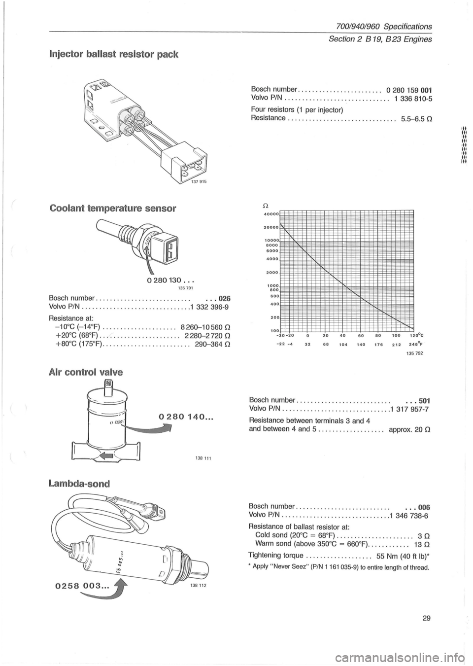
Injector ballast resistor pack
Coolant temperature sensor
0280130 ... 135791
Bosch number. . . . . . . . . . . . . . . . . . . . . . . . . . . . .. 026
Volvo PIN ....................... ........ 1 332 396-9
Resistance
at:
-10°C ( - 14°F) .................... . 8260-10560 n
+20°C (68°F) ....................... 2280-2720 n
+80°C (175 °F) ......................... 290-364 n
A ir control valve
Lambda-sond
0258~3 ... '
70019401960 Specifications
Section
2 B 19, B 23 Engines
Bosch number ...................... " 0 280 159 001
Volvo PIN. . . . . . . . . . . . . . . . . . . . . . . . . . . . .. 1 336 810-5
Four resistors
(1 per injector)
Resistance . . . . . . . . . . . . . . . . . . . . . . . . . . . . .
.. 5.5-6.5 n
40000
20000
10000 8000 6000
4000
2000
1000 800 600 400
200
100
--
il
-30 -20 0 20 40 60 80 100 120°C
-22 -4 32 68 104 140 176 212 248°F
135792
Bosch number. . . . . . . . . . . . . . . . . . . . . . . . . . . . .• 501
Volvo PIN ................. " ..... ....... 1 317957-7
Resistance between terminals 3 and 4
and between 4 and 5 . . . . . . . . . . . . . . . . .
.. approx. 20 n
Bosch number. . . . . . . . . . . . . . . . . . . . . . . . . . . . .. 006
Volvo PIN ............................... 1 346 738-6
Resistance of
ballast resistor at:
Cold sond (20°C = 68°F) . . . . . . . . . . . . . . . . . . . . .. 3 n
Warm sond (above 350°C = 660°F) ............ 13 n
Tightening torque. . . . . . . . . . . . . . . . . .. 55 Nm (40 ft Ib)*
• Apply "Never Seez" (PIN 1161 035-9) to entire length of thread .
29
III
IN III ·11 III
III
III III
Page 33 of 168
70019401960 Specifications
Section 2 B 19, B 23 Engines
Group 25 Intake and Exhaust systems
Turbocharged engines
En gin e type ................................... B 19ET B23ET
C harge pressure, at full load .............. rlmin 3500
3500
checking ............ kPa (psi) 60-70 (8.5-10.0) 45-53 (6.4-7.5)
adjusting ............ kPa (psi) 64-70 (9. 1-10.0)
50 (7.1)
Charge air overpressure,
switch, opens at ...................... kPa (psi) 85-95 (12.1-13.5) 65-75 (9.2-10.7)
Charge air pressure, switch, closes at .. kPa (psi) -15-25 (2.1-3.6)
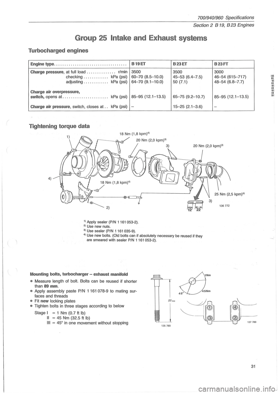
Tighten ing torque data
4)
1) Apply sealer (PIN 1161053-2). 2) Use new nuts.
3) Use sealer (PIN 1 161 035-9).
4) Use new bolts . (Old bolts can if absolutely necessary be reused if they
are smeared with sealer PIN 1161053·2).
Mounting bolts, turbocharg er - ex hau st m anifold
•
Measure length of bolt. Bolts can be reused if shorter
than
89 mm.
• Apply assembly paste PIN 1 161 078-9 to mating sur
faces and threads
• Fit new locking plates
•
Tighten bolts in three stages according to below
Stage I = 1 Nm (0.7 ft Ib)
II = 45 Nm (32.5 ft Ib)
III = 45 ° in one movement without stopping
89mm
135780
sfJ
Nm
45Nm 45·
B23FT
3000
46-54 (615-717)
48-54 (6.8-7.7)
85-95 (12.1-13.5)
-
31
Page 35 of 168
(
70019401960 Specifications
Section
2 B 19, B 23 Engines
Group 28 Ignition system
~
fif!}jJ~
~ 1348~
Type. . . . . . . . . . . . . . . . . . . . . . . . . . . . . . . . . . . . . . . . . . . . . . . . . . . . . . . . 8reakerless
Firing order. . . . . . . . . . . . . . . . . . . . . . . . . . . . . . . . . . . . . . . . . . . . . . . . . . 1-3 -4-2
Ig nition sett ing (8.TD.C.)
E ngin e type 12.5 rls 41.7 rls
750 r/min 2500 r/min
819 E* 10 ? 28-33
819 ET* 15° 23-26°
823E* 10° 28-33°
823ET 10°1) -
823FT 12°2) -
• Vacuum unit disconnected. 1) At idle = 14.1 rls (850 r/min) . 2) At 15 rls (900 r/min).
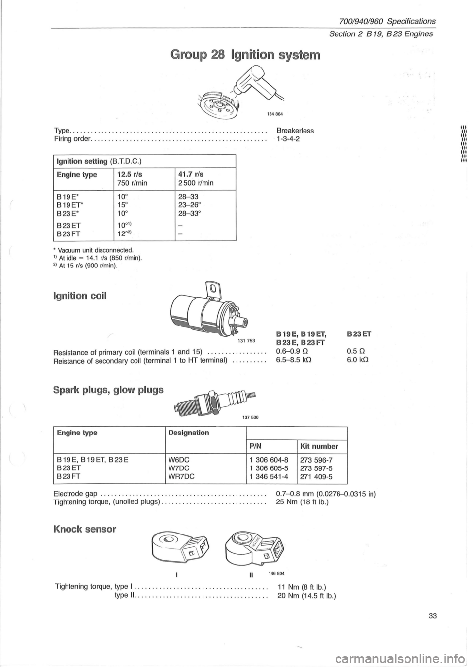
Ignition coil
131753
Resistance of primary coil (terminals 1 and 15) ................ .
B 19 E, B 19 El,
B23E, B23FT
0.6-0.90
6.5-8.5 kO Reistance of secondary coil (terminal 1 to HT terminal) ......... .
Spark plugs, glow plugs
Engine type Designation
PIN Kit numb er
819E, 819ET, 823E W6DC 1 306604-8 273596-7
823ET W7DC 1 306605-5 273597-5
823FT WR7DC 1 346541-4 271 409-5
B23ET
0.50
6.0 kO
Electrode
gap .............................................. .
Tightening torque,
(unoiled plugs) ............................. . 0
.
7-0.8 mm (0.0276-0.0315 in)
25 Nm (18
ft lb.)
Knock sensor
II 146804
Tightening torque, type I ............................ ......... . 11 Nm (8 ft lb.) type 11. ................•..•.....•........... 20 Nm (14.5 ft lb.)
33
III '111 III III III ·111 III ,11' III
Page 37 of 168
(
70019401960 Specifications
Section 2 B 200, B 230 Engines
Section 2 B 200, B 230 Engines
Group 20 General . . . . . . . . . . . . . . . . . . . . . . . . . . . . . .. 31
Group 21 Engine block ........................... 32
Group
22 Lubricating system ....................... 38
Group
23 Fuel system ......... ................ .. 39
Group
25 Intake and exhaust systems. . . . . . . . . . . .. 60
Group 26 Cooling system. . . . . . . . . . . . . . . . . . . . . . . .. 62
Group
28 Ignition system. . . . . . . . . . . . . . . . . . . . . . . .. 63
..... 1/
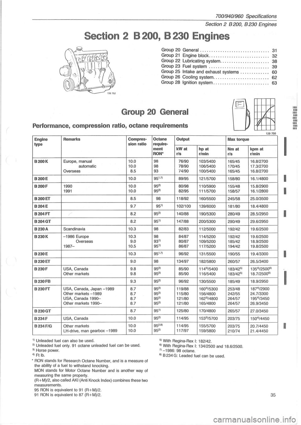
j. Group 20 General
Performance , compression ratio, octane requirements
Engine Remarks Compres-
type slon ratio
B200K Europe, manual 10.0 automatic 10.0 Overseas
8.5
B200 E 10
.0
B200 F 1990 10.0 1991 10.0
B200ET 8.5
B204
E 9.7
B204FT / 8.2
B204GT 8.2
B230A Scandinavia 10 .3
B230K -1986 Europe 10.3 Overseas 9.0 1987-10.5
B230 E 10.3
B230ET 9
.0
B230 F USA, Canada 9
.8 Other markets 9.8
B230FB 9.3
B230 FT USA , Canada, Japan -1989 8.7 Other markets -1989 8 .7
USA, Canada 1990-8.7 Other markets 1990-8.7
B230GT 8.7
B234F USA, Canada 10.0
B234 F IG Other markets 10.0
LH-drive, man gearbox -1989 10.0
11 Unleaded fuel can also be used . 21 Unleaded fuel only. 91 octane unleaded fuel can be used. 31 Horse power. 41 Ft lb.
•
RON stands for Resea rch Octane Number, and is a measure of
the ability of a fuel to withstand knocking. MON stands for Motor Octane Number and is another way of
measuring the same property.
(R+M)/2,
also called AKI (Anti Knock Index) combines these two
m eas urem ents .
95
RON is equivalent to 91 (R+M)/2. 91 RON i s equivalent to 87 (R+M) /2.
Octane Output Max torque require-ment kWat hp at Nm at RON" rls
r/min rls
98 76/90
103/5400 165/45 98 78/90 106/5400 170/45 93 74/90 100/5400 165/45
95 1
.
71 89/95 121/5700 158/80
9521 80/98 110/5900 155/48 9521 82/95 11115700 158/57
98
118/92 160/5500 245/58
9511 102/100 139/6000 181/80
952
) 140/88 190/5300 280/49
9511 147188 200/5300 290/49
98 82/83 112/5000 192/42
98 84/87
114/5200 192/42 9311 80/87 109/5200 185/42 9511 86/87 117/5200 194/42
95 1
.
71 96/92 131/5500 190/55
98 134/97 182/5800 260/57
9521 85/90 11431/5400 183/4251
9521 85/90 116/5400 183/4251
9521 96/92 130/5500 185/49
9521 119/88 16031/5300 253/48 9521 115/80 156/4800 242/55 9521 121180 16231/4800 264/57 9521 121/80 165/4800 264/57
9511 125/80 170/4800 265/57
9521 114/95 15331/57 00
203/75
952
.81 114/95 155 /5700 203/75
9521 117/97 159/5800 210/74
51 With Regina-Re x I: 182/42 .
61 With Regina-Rex I: 134/2500 and 18.6/ 2500 . 71_1986: 98 octane .
81 B 234 G: Leaded fuel can be used .
~ ""
129750
kpm at r/min
16.8/2700
17.3/2700
16 .8/2700
16 .1/4800
15 .8/2900
16.1/2800
25 .0/3500
18.4/4800
28 .5/2950
29 .6/2950
19 .6 /2500
19.6/2500 18 .9 /2500 19 .8/2500
19.4/3300
26.5/3400 135
41/250061
18.7/250061
18 .9/2950
18rl/2900
24.7/3300
19541/3450 26 .9 /34 50
27.0/3450
150
41/ 4450
20 .7/4450 21.4/4450
35
I
I
I
I
I
I
I
""
III
III· III
III· ·111 III '111 III
Page 43 of 168
(
70019401960 Specifications
Section
2 B 200, B 230 Engines
Bea rings
Main bearings
Two types of main bearings are in use. Upper and lower
shells
on same journal must be same type.
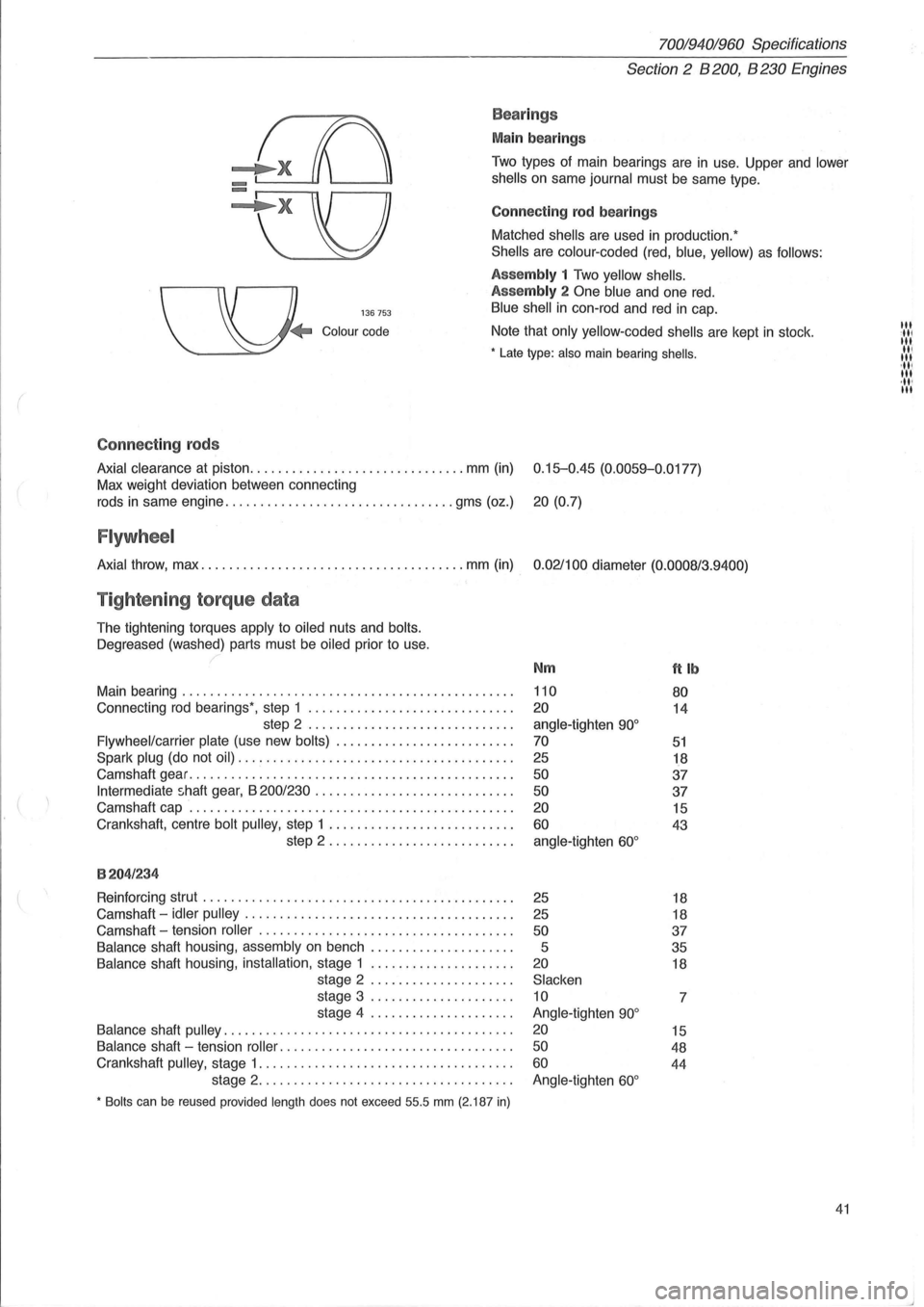
Connect
ing rod bearings
Matched
shells are used in production:
Shells are colour -coded (red, blue, yellow) as follows:
136753
Assembly 1 Two yellow shells.
Assembly
2 One blue and one red.
Blue shell in con-rod and red in cap.
Colour code Note that only yellow-coded shells are kept in stock .
• Late type: also main bearing shells .
Connect ing rods
Axial clearance at piston ............................... mm (in) 0.15-0.45 (0.0059-0.0177)
Max weight deviation between connecting
rods
in same engine ................................. gms (oz.) 20 (0.7)
Flywheel
Axial throw, max ...................................... mm (in) 0.021100 diameter (0.0008/3.9400)
Tightening torque data
The tightening torques apply to oiled nuts and bolts.
Oegreased
(washed) parts must be oiled prior to use.
Main bearing
............................................... .
Connecting
rod bearings', step 1 ............................. .
step 2
............................. .
Flywheel/carrier plate (use new bolts) ...................... ... .
Spark plug (do not oil) ....................................... .
Camshaft gear
.............................................. .
Intermediate shaft gear, B 200/230 ............................ .
Camshaft cap
.............................................. .
Crankshaft, centre
bolt pulley, step 1 .......................... .
step 2 .
.. ....................... .
8204/234
Reinforcing strut ............................................ .
Camshaft -
idler pulley ...................................... .
Camshaft -tension
roller .................................... .
Balance shaft housing, assembly on bench .................... .
Balance shaft housing, installation, stage 1 .................... .
stage 2
.................... .
stage 3
.................... .
stage 4
.................... .
Balance shaft pulley ......................................... .
Balance shaft -tension roller .. ............................... .
Crankshaft
pulley, stage 1 .................................... .
stage 2
.................................... .
• Bolts can be reused provided length does not exceed 55.5 mm (2.187 in)
Nm
110
20
angle-tighten 90°
70
25
50
50
20
60
angle-tighten 60°
25
25
50
5
20
Slacken
10
Angle-tighten
90°
20
50
60
Angle-tighten 60°
ftlb
80
14
51
18
37
37
15
43
18
18
37
35
18
7
15
48
44
41
III :11' III II, III 'III III ,11' III