1982 VOLVO 700 torque
[x] Cancel search: torquePage 119 of 168
(
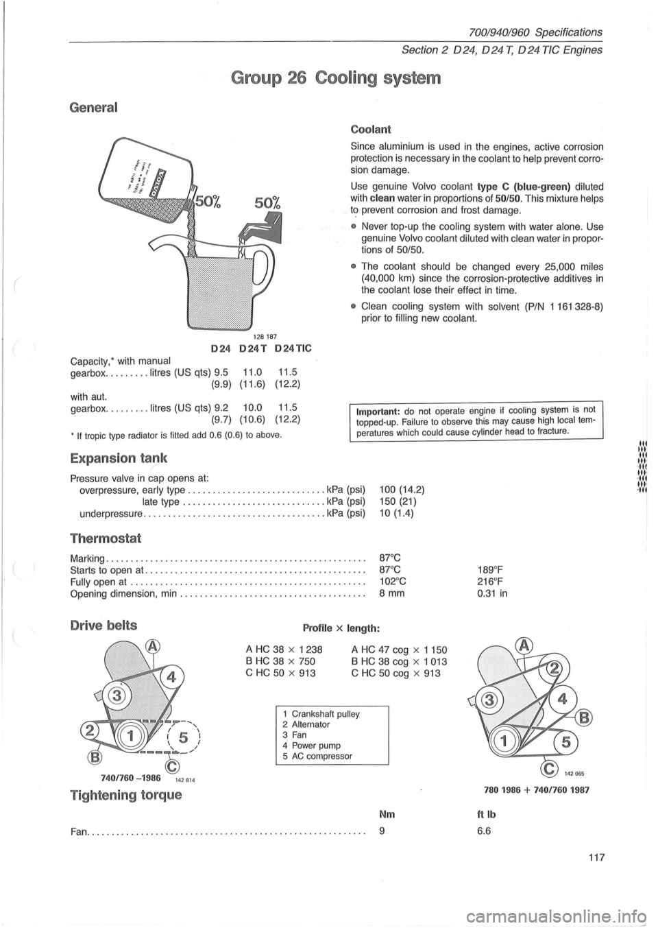
General
024
Capacity: with manual
gearbox ......... litres (US qts) 9.5
(9.9)
with
aut.
gearbox ......... litres (US qts) 9.2
(9.7)
70019401960 Specifications
Section 2 024, 024 T, 024 TIC Engines
Group 26 Cooling system
128187
024T 024TIC
11.0 11.5
(11.6) (12
.
2)
10.0 11.5
(10.6) (12.2)
Coolant
Since aluminium is used in the engines, active corrosion
protection is necessary in the
coolant to help prevent corro
sion damage.
Use genuine Volvo coolant type C (blue-green) diluted
with clean water in proportions of 50/50. This mixture helps
to prevent corrosion and frost damage.
• Never top-up the cooling system with water alone . Use
genuine
Volvo coolant diluted with clean water in propor
tions of 50/50.
•
The coolant should be changed every 25,000 miles
(40,000
km) since the corrosion-protective additives in
the coolant lose their effect in time.
• Clean cooling system with solvent (P/N 1 161 328-8)
prior to
filling new coolant.
• If tropic type radiator is filled add 0.6 (0.6) to above.
Important: do not operate engine if cooling system is not topped-up. Failure to observe this may cause high local temperatures which could cause cylinder head to fracture .
Expansion tank /
Pressure valve in cap opens at:
overpressure, early type ............................ kPa (psi)
late type ............................. kPa (psi)
underpressure
............... ...................... kPa (psi)
Thermostat
Marking ..................................................... .
Starts to open
at ............................................ .
Fully open
at ............................................... .
Opening dimension, min ..................................... .
Drive belts Profile x length:
100 (14.2)
150 (21)
10(1.4)
87°C
87 °C
102°C
8 mm
A HC 38 x 1238
B HC 38 x 750
C HC
50 x 913
A HC 47 cog x 1 150
B HC 38 cog x 1 013
C
HC 50 cog x 913
--, / , I 5 I 1 I
--~_/
7401760 -1986 142814
Tightening torque
1 Crankshaft pulley 2 Alternator 3 Fan 4 Power pump
5 AC compressor
Nm
Fan.......................... ............................... 9
189°F
216 °F
0 .
31 in
780 1986 + 7401760 1987
ftlb
6.6
117
lit til' lit ,", ·111 11,1 ·111 1111 ,11'
--'
Page 121 of 168
(
70019401960 Specifications
Section
3 Electrical system
Group 32 Alternator
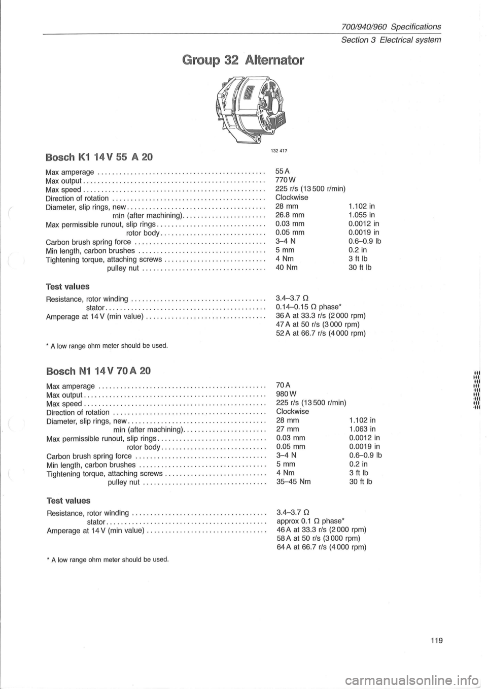
Bosch K1 14 V 55 A 20
Max amperage ............................................. .
Max output ................................................. .
Max speed ................................................. .
Direction of rotation .
........................................ .
Diameter,
slip rings, new ..................................... .
min (after machining) ...................... .
Max permissible runout, slip rings ............................. .
rotor body
............................ .
Carbon brush spring force
............... .................... .
Min length, carbon brushes .................................. .
Tightening torque, attaching screws
........................... .
pulley nut ................................. .
Test values
Resistance, rotor winding .................................... .
stator
..... ...................................... .
Amperage
at 14 V (min value) ................................ .
, A low range ohm meIer should be used.
Bosch N1 14 V 70 A 20
Max amperage ............................................. .
Max output
................................................. .
Max speed
...................... .. ......................... .
Direction of rotation
......................................... .
Diameter,
slip rings, new ..................................... .
min (after machining)
...................... .
Max permissible runout,
slip rings ............................. .
rotor body
............................ .
Carbon brush spring force
................................... .
Min length, carbon brushes .................................. .
Tightening torque, attaching screws .
.......................... .
pulley nut ................................. .
Test values
Resistance, rotor winding .................................... .
stator
......................................... .. .
Amperage
at 14 V (min value) ................................ .
, A low range ohm meter should be used.
132417
55A
770W
225 rls (13500 r/min)
Clockwise
28 mm
26.8
mm
0.03 mm
0.05 mm
3-4N
5 mm
4 Nm
40 Nm
3.4-3.70
0.14-0.15 0 phase'
1.102 in
1.055 in
0.0012 in
0.0019 in
0.6-0.9Ib
0.2 in
3 ft Ib
30 ft Ib
36 A at 33.3 rls (2000 rpm)
47 A at 50 rls (3000 rpm)
52A at 66.7 rls (4000 rpm)
70A
980W
225 rls (13500 r/min)
Clockwise
28 mm
27 mm
0.03 mm
0.05 mm
3-4N
5 mm
4 Nm
35-45 Nm
3.4-3.70
approx 0.1 0 phase'
1.102 in
1.063 in
0.0012 in
0.0019 in
0.6-0.9Ib
0.2 in
3 ft Ib
30 ft Ib
46 A at 33.3 rls (2000 rpm)
58 A at 50 rls (3000 rpm)
64A at 66.7 rls (4000 rpm)
119
HI Itli til III ·111 III ·tli III ,til
Page 122 of 168
70019401960 Specifications
Section 3 Electrical system
Bosch N1 14 V 31/S0A
Max amperage ............................................. .
Max output
................................................. .
Max speed
................................................. .
Direction
of rotation .................................... ..... .
Diameter,
slip rings, new .................................... . .
min (after machining)
...................... .
Max
permissible runout, slip rings ............................. .
rotor body
............................ .
Carbon brush spring force .
.................................. .
Min
length , carbon brushes .................................. .
Tightening torque, attaching screws
........................... .
pulley nut ................................. .
Test values
Resistance rotor winding ..................................... .
stator
........................................... .
Amperage
at 14 V (min value) ................................ .
Bosch N1 14 V 34 /90 A 20
Max amperage ................................ ............. .
Max output .
............ ........ ......................... ... .
Max speed
............... ................................ .. .
Direction
of rotation ......................................... .
Diameter ,
slip rings, new ..................................... .
min (after machining)
............................... .
Max
permissible run-out , slip rings ............................ .
rotor body
........................... .
Carbon brush spring force
................................. .. .
Min
length, carbon brushes .................................. .
Tightening torque, attaching screws .
.......................... .
pulley nut .................................. .
Test values
Resistance , rotor winding .................................... .
stator
........................................... .
Amperage
at 14 V (min value) ................................ .
* A low range ohm meter should be used.
120
80A
1120W
250 rls (15000 r/min)
Clockwise
28 mm
26.8
mm
0.03 mm
0.05 mm
3-4N
5 mm
4 Nm
45-55 Nm
2.9 Q
approx. 0.09 Q phase
1.102 in
1.056 in
0 .0012 in
0 .0019 in
0.6--0 .9Ib
0.2 in
3 ft Ib
33-40 ft Ib
31 A at 25 rls (1 500 rpm)
80 A at 100 rls (6000 rpm)
90A
1260W
225 rls (13500 rpm)
Clockwise
28 mm
27 mm
0.03 mm
0.05 mm
3-4N
5 mm
4 Nm
35-45 Nm
2.8-3.1
Q
0.07 -0 .08 Q*
1.102 in
1 .063 in
0.0012 in
0 .0019 in
0 .6--0.9Ib
0 .2
in
3 ft Ib
30 ft Ib
34 A at 25 rls (1 500 rpm)
60 A at 33.3 rls (2000 rpm)
90 A at 100 rls (6000 rpm)
Page 123 of 168
Bosch N1 14 V 31/100 A
Max amperage ........................... .................. .
Max output ............................................. 00 •••
Max speed ........................... 0 •••••••••••••••• 0 •••••
Direction of rotation ................ ............ 0 •••••••••••••
Diameter, slip rings, new ..................................... .
min (after machining) .
................ 0 •••• •
Max permissible run-out, slip rings ........................ 0 • 0 ••
rotor body .... o •••••••••••••••••• 0 ••••
Carbon brush spring force ............................. 0 • • 0 •• •
Min length, carbon brushes .................................. .
Tightening torque, attaching screws .
.......................... .
pulley nut .......... o ••••••••••••••••• o •••••
Test values
Resistance, rotor winding .................................... .
( stator ................. 0 ••••••••••••••••••••••• • ••
Amperage at 14 V (min value) ..................... ........ .. 0 •
• A low range ohm meter should be used .
Bosch NC 14 V 60 /120 A
Volvo PiN ............ ................... 0 •••••• ••• ••••••••••
Bosch number ........................... 0 •••••••••• 0 ••••••••
Max amperage ............................................ . .
Max output
................................ 0 •••••••••••••••••
Max speed ......................................... 0" 0 •••••
Direction of rotation ................................ 0 ••• ••••••
Diameter , slip rings, new ........ . 0 ••••••••••••••••••\
••••• •••••
min (after machining) ...................... .
Max permissible run-out,
slip rings ................. 0 •••••••••••
rotor body ........................... .
Carbon brush spring force ...
........................... ..... .
Min length, carbon brushes ... 0 • •••••••••• 0 ••••••• 0' 00.00 •••••
Tightening torque, attaching screws ................. 0 ••••• 0 ••••
pulley nut ........... 0 ••••••••••• 0 •• 0 0 • 0 ••••
Test va lues
Resistance, rotor winding ................... .... 0 •• •••••••••••
stator ..................................... ...... .
Amperage
at 14 V (min value) .................. 0 ••••••••• 0 ••••
Nippon Denso 80 A
Volvo PiN ............. ..................................... .
Nippon Denso number .
................ 0 •••••• 0 ••••• 0 •••••••• •
Max amperage .............. ............................... .
Max output .................... ............................. .
Max speed ............................... 0 ••• ••••••• •••• ••••
Direction of rotation ..... 0 •••••• 0 •••••••••••••••••• 0 ••••••••••
70019401960 Specifications
Section
3 E lectrical system
100A
1400W
250 rls (15000 rpm)
Clockwise
28 mm
27 mm
0.03 mm
0.05 mm
3-4N
5 mm
4 Nm
45-55 Nm
2 .6
n
ca 0.05 n
1 .063 in
0.0012 in
0.0019 in
0 .6-0.9Ib
0.2 in
3 ft Ib
33-40 ft Ib
31 A at 25 rls (1 500 rpm)
100 A at 100 rls (6000 rpm)
3523420
0120465 006
120A
1680W
300 rls (18000 r/min)
Clockwise
15 mm (0.59 in)
14
mm (0. 55 in)
0,003 mm (0.0001 in)
0,005 mm (0.0002 in)
3-5 N (0.3-0.5 kp)
5 mm (0.2 in)
4 Nm (3 ft Ib)
45-55 Nm (33-40 ft Ib)
2,6 n
0,02 n
60 Avid 30 rls (1 800 r/min)
120 Avid 100 rls (6000 r/min)
1398327
100211-8370
80A
1120W
300 rls (18000 r/min)
Clockwise
121
I
III II III II III -II III oil III
j
Page 125 of 168
(
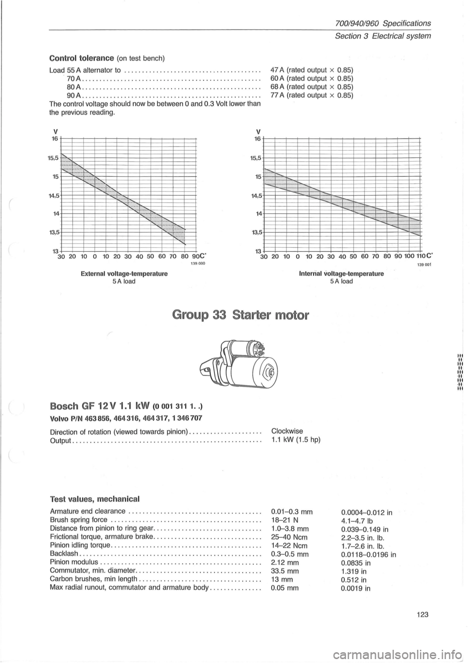
Control to le ra nce (on test bench)
Load
55 A alternator to ............... ............. ....... ... .
.
70A ...................... ........................... . .
80A .................. ...................... .......... .
90A ......... ......................................... .
The
control voltage should now be between 0 and 0.3 Volt lower than
the previous reading.
V 16
15,5 .
15
'"
v
15,5
15 .
14,5 14
13,5
70019401960 Specifications
Section 3 E lectrical system
47 A (rated output x 0.85)
60 A (rated output x 0.85)
68 A (rated output x 0.85)
77 A (rated output x 0.85)
13 30 20 10 0 10 20 30 40 50 60 70 80 90C' 13 30 20 10 0 10 20 30 40 50 60 70 80 90100 110C'
Exte rn al volt age- te m perature 5A load
1:l9000
Int erri al volt age- te mp erature 5A load
G ro up 33 S ta rt er m otor
Bosch GF 12V 1.1 kW (00013111 .. )
V olvo PIN 463856 , 464 316, 464317,1346 707
Direction of rotation (viewed towards pinion) ............... .... . .
Output . . ......................................... , ......... .
Test values , mechan ical
Armature end clearance ....... ................... .......... . .
Brush spring force
.......................................... .
Distance from pinion to ring gear ... .
.......................... .
Frictional torque, armature brake ............................ .. .
Pinion
idling torque ........... .. ...................... ..... .. .
Backlash ..................... .............................. .
Pinion
modulus . .. .............................. ............ .
Commutator , min . diameter
................................... .
Carbon brushes, min
length .. ............................ .... .
Max
radial runout, commutator and armature body ... ........... .
Clockwise
1 .1 kW (1.5 hp)
0.01-0.3 mm
18-21 N
1.0-3.8 mm
25-40 Ncm
14-22 Ncm
0 .
3-0.5 mm
2.12 mm
33.5 mm
13 mm
0 .
05 mm 0.000
4-0
.012 in
4.1-4.7Ib
0 .039-0.149 in
2.2-3.5 in. lb.
1 .7 - 2.6 in. lb.
0.0118-0.0196 in
0.0835 in
1 .319 in
0 .512 in
0 .0019 in
1 39001
123
III III III III III ,11, III ·111 III
Page 126 of 168
70019401960 Specifications
Section 3 Electrical system
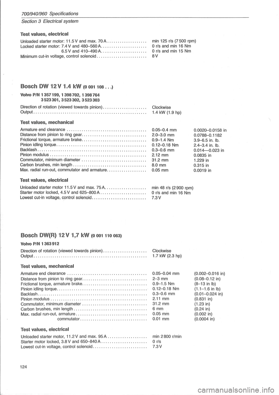
Test
values, electr ica l
Unloaded starter motor: 11.5 V and max. 70 A .................. .
Locked starter motor: 7.4 V and
480-560A ..................... .
6.5 V and
410-490A ..................... .
Minimum cut-in voltage, control solenoid
....................... .
Bosch OW 12 V 1.4 kW (0001108 ... )
Volvo PIN 1 357199, 1 398702, 1 398764
3523301, 3523302,
3523303
Direction of rotation (viewed towards pinion) .................... .
Output ...................................................... .
Test values, mechanical
Armature end clearance ..................................... .
Distance
from pinion to ring gear .............................. .
Frictional torque, armature brake
................ ... ........... .
Pinion idling torque
.......................................... .
Backlash
.................... ............................... .
Pinion modulus
............................................. .
Commutator, minimum diameter
.............................. .
Carbon brushes, min length
.................................. .
Max. radial run-out, commutator and armature .................. .
Test values, electr ica l
Unloaded starter motor 11.5 V and max. 75 A ..... .............. .
Starter motor locked, 4.5 V and
625-800 A ..................... .
Lowest cut-in voltage, control solenoid
......................... .
Bosch OW(R) 12V 1,7 kW (0001110063)
Volvo PIN 1 363912
Direction of rotation (viewed towards pinion) .................... .
Output ................................................... .. .
Test values, mechanical
Armature end clearance ..................................... .
Distance from pinion
to ring gear .............................. .
Frictional torque, armature brake
.............................. .
Pinion idling torque
........................................... '
Backlash ................................................... .
Pinion modulus
............................................. .
Commutator, minimum diameter
............................. . .
Carbon brushes, min length .
................................. .
Max. radial run-out, armature
................................. .
commutator
............................... .
Test values, electr ica l
Unloaded starter motor, 11.2 V and max. 95 A .................. .
Starter motor locked, 3.8 V and
650-840 A ..................... .
Lowest cut-
in voltage, control solenoid ......................... .
124 min
125
rls (7500 rpm)
OrIs and min 16 Nm
OrIs and min 15 Nm
8V
Clockwise
1.4
kW (1.9 hpj
0.05-0.4
mm
2 .0-3.0 mm
0.9-1.4 Nm
0.12 -0.18 Nm
0.3-0.6 mm
2.12 mm
31.2 mm
8.0 mm
0.05 mm
min 48 rls (2900 rpm)
OrIs and min 16 Nm
7.3V
Clockwise
1.7 kW (2.3
hpj
0.05-0.04
mm
2-3 mm
0.9-1.5 Nm
0.12-0.18 Nm
0 .3-0.6 mm
2.11 mm
31.2 mm
6mm
0.05 mm
0 .01 mm
min 2800 r/min
OrIs
7.3V
0.0020-0.0158 in
0.0788-0 .1182
3 .9-6.5 in. lb.
2.4-3.4 in. lb.
0.014-0.023 in
0.0835 in
1.229 in
0.315 in
0.0019 in
(0.002-0.016 in)
(0.08-0.12 in)
(8-13
in Ib)
(1.1-1.6 in Ib)
(0.01-0.024 in)
(0.831 in)
(1.23 in)
(0.24 in)
(0. 002 in)
(0.0004 in)
Page 127 of 168
(
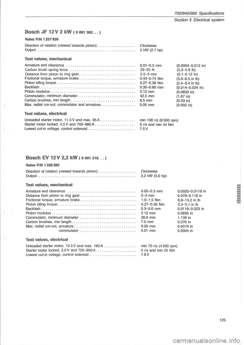
Bosch JF 12V 2 kW (0001362 ... )
Volvo PIN 1 257939
Direction of rotation (viewed towards pinion) .................... .
Output ..................................................... .
Test va lu es , mechanical
Armature end clearance ..................................... .
Carbon brush spring force .
.................................. .
Distance from pinion to ring gear ..
............................ .
Frictional torque, armature brake .............................. .
Pinion
idling torque ........................................ .. .
Backlash ...... ............................................. .
Pinion
modulus ............................................. .
Commutator, minimum diameter
.............................. .
Carbon brushes, min
length .................................. .
Max .
radial run-out, commutator and armature .................. .
Test v alues , e lec tric al
Unloaded starter motor, 11.5 V and max. 95 A .................. .
Starter motor
locked, 4.5 V and 700-880 A .................. ' .. .
Lowest cut-in
voltage, control solenoid ......................... .
Bosch EV 12V 2,2 kW (0001218 ... )
Volvo PIN 1 328392
Direction of rotation (viewed towards pinion) .................... . ,/ Output ..................................................... .
Test values , mechan ical
Armature end clearance ..................................... .
Distance from pinion to ring gear
.............................. .
Frictional torque, armature brake .............................. .
Pinion
idling torque .......................................... .
Backlash.. . . .. ,.,',.,." ..... " .. " ..... , ..... ,., .. ,., .. .. .
Pinion
modulus. , .... , . ... , . , ............... ........ , .... , .. .
Commutator, minimum diameter
.. , , .. , .. , ....... , .... , . , .. , .. .
Carbon brushes, min
length, , ........... , .... , .... , .... , .. , .. ,
Max. radial run-out, armature .. , .. , . . , , , .............. , . , .. , .. .
commutator
....... , ..... , .. , , .... , . , .. , .. .
Test va lu es , e lectr ica l
Unloaded starter motor, 10.5 V and max. 160 A ... , .... . , . , .. , .. .
Starter motor
locked, 3.0V and 720-950 A " ., ........... , ..... .
Lowest cut-in
voltage, control solenoid, , , , ....... , .. , .. , . , .. , .. ,
70019401960 Specifications
Section 3 Electrica l system
Clockwise
2 kW (2.7 hpj
0.01-0.3 mm
23-25 N
2.5-3 mm
0.44-0,74 Nm
0.27-0 .39 Nm
0.35-0.60 mm
2.12 mm
42,5 mm
8.5 mm
0,05 mm
(0.0004-0 .012 in)
(5,2-5.6 Ib)
(0.1-0 .12 in)
(3.9-6 .5 in Ib)
(2.4-3.4 in Ib)
(0.014-0.024 in)
(0.0835 in)
(1.67 in)
(0.33 in)
(0.002 in)
min 108 rls (6500 rpm)
OrIs and min 44 Nm
7.5V
Clockwise
2,2 kW (3.0 hpj
0.05-0.3 mm
2-3 mm
1.0-1.5 Nm
0,27-0.35 Nm
0 .3-0.6 mm
2,12 mm
28 ,9 mm
7.0 mm
0 .05 mm
0,01 mm
min
70 rls (4200 rpm)
OrIs and min 25 Nm
7.8V
0.0020-0.0118 in
0.079-0.118 in
8.8--13.2 in Ib
2.4-3.1 in Ib
0.0118--0.023 in
0.0835 in
1.139 in
0.276 in
0 .0019 in
0,0004 in
125
J
Page 141 of 168
70019401960 Specifications -------------------------------------------------------------
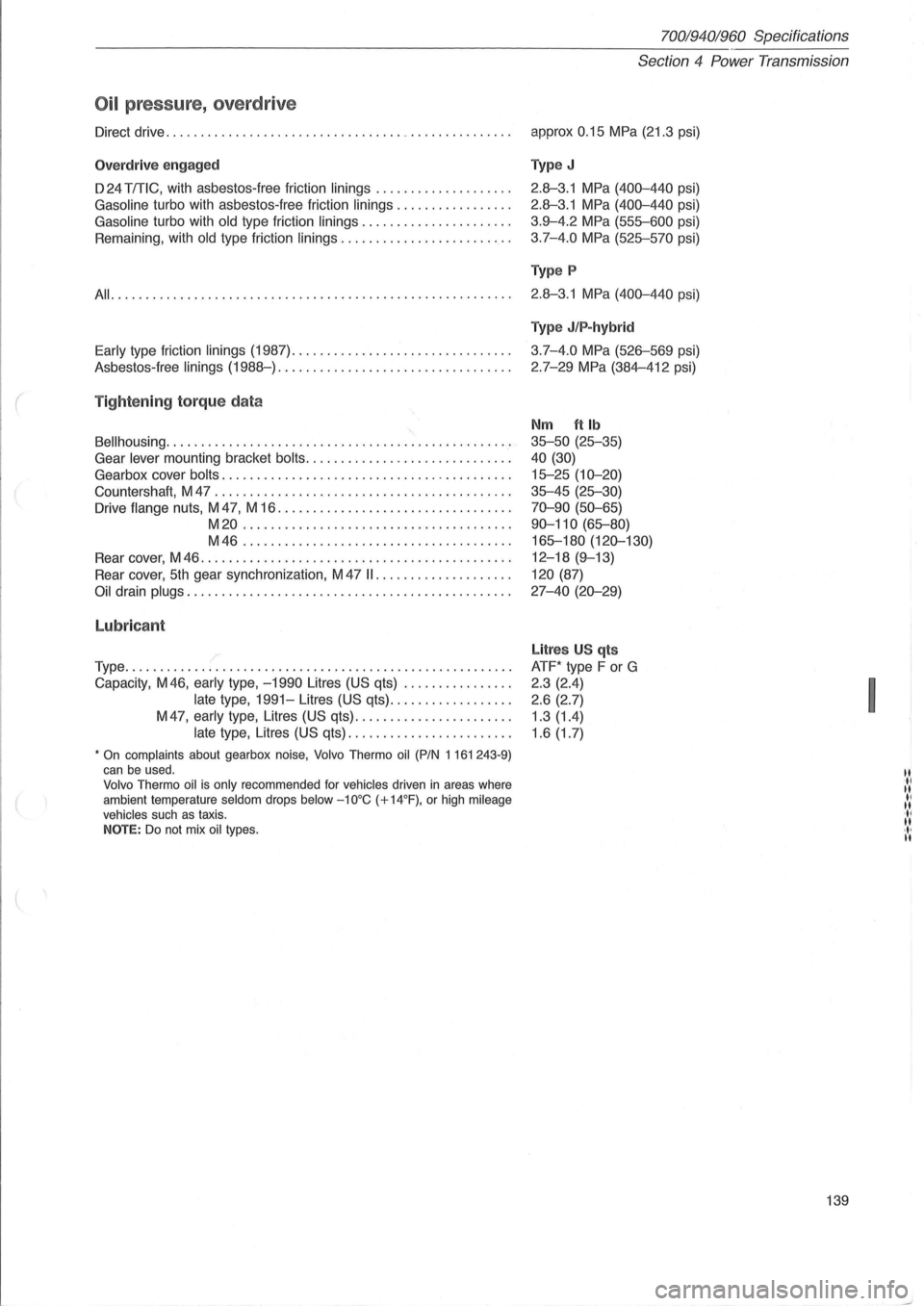
Oil pressure, overdrive
Direct drive .............................................. .. . .
Overdr ive engaged
D 24 TmC, with asbestos-free friction linings ................... .
Gasoline turbo with asbestos-free friction linings ................ .
Gasoline turbo with old type friction linings ..................... .
Remaining, with
old type friction linings ........................ .
All ......................................................... .
Early type friction linings (1987) ............................... .
Asbestos -
free linings (1988-) ................................. .
( Tightening torque data
8ellhousing ................................................. .
Gear
lever mounting bracket bolts ............................. .
Gearbox cover
bolts ......................................... .
Countershaft, M 47
.......................................... .
Drive
flange nuts, M 47, M 16 ................................. .
M20 ...................................... .
M46 ...................................... .
Rear cover, M 46
............................................ .
Rear cover,
5th gear synchronization, M 47 II ................... .
Oil drain plugs .............................................. .
Lubricant
/ Type ....................................................... .
Capacity, M46,
early type, -1990 Litres (US qts) ............... .
late type, 1991-Litres (US qts) ................. .
M
47, early type, Litres (US qts) ...................... .
late type, Litres (US qts) ....................... .
• On complaints about gearbox noise, Volvo Thermo oil (PIN 1161 243-9) can be used. Volvo Thermo oil is only recommended for vehicles driven in areas where
ambient temperature seldom drops below -10°C (+14°F), or high mileage vehicles such as taxis. NOTE: Do not mix oil types.
Section 4 Power Transmission
approx 0.15 MPa (21.3 psi)
Type J
2.8--3.1 MPa (400-440 psi)
2.8--3.1 MPa (400-440 psi)
3.9-4.2
MPa (555-600 psi)
3.7-4.0
MPa (525-570 psi)
Type P
2.8--3.1 MPa (400-440 psi)
Type J/P-hybrid
3.7-4.0 MPa (526-569 psi)
2.7-29
MPa (384-412 psi)
Nm ft Ib
35-50 (25-35)
40 (30)
15-25 (10-20)
35-45 (25-30)
70-90 (50-65)
90-110
(65-80)
165-180
(120-130)
12-18 (9-13)
120 (87)
27-40 (20-29)
Litres U S qts
ATF* type F or G
2 .3 (2.4)
2.6 (2.7)
1.3 (1.4)
1.6 (1.7)
139
I
.til I! II I! II I! ·1 , I!