1982 VOLVO 700 torque
[x] Cancel search: torquePage 75 of 168
{
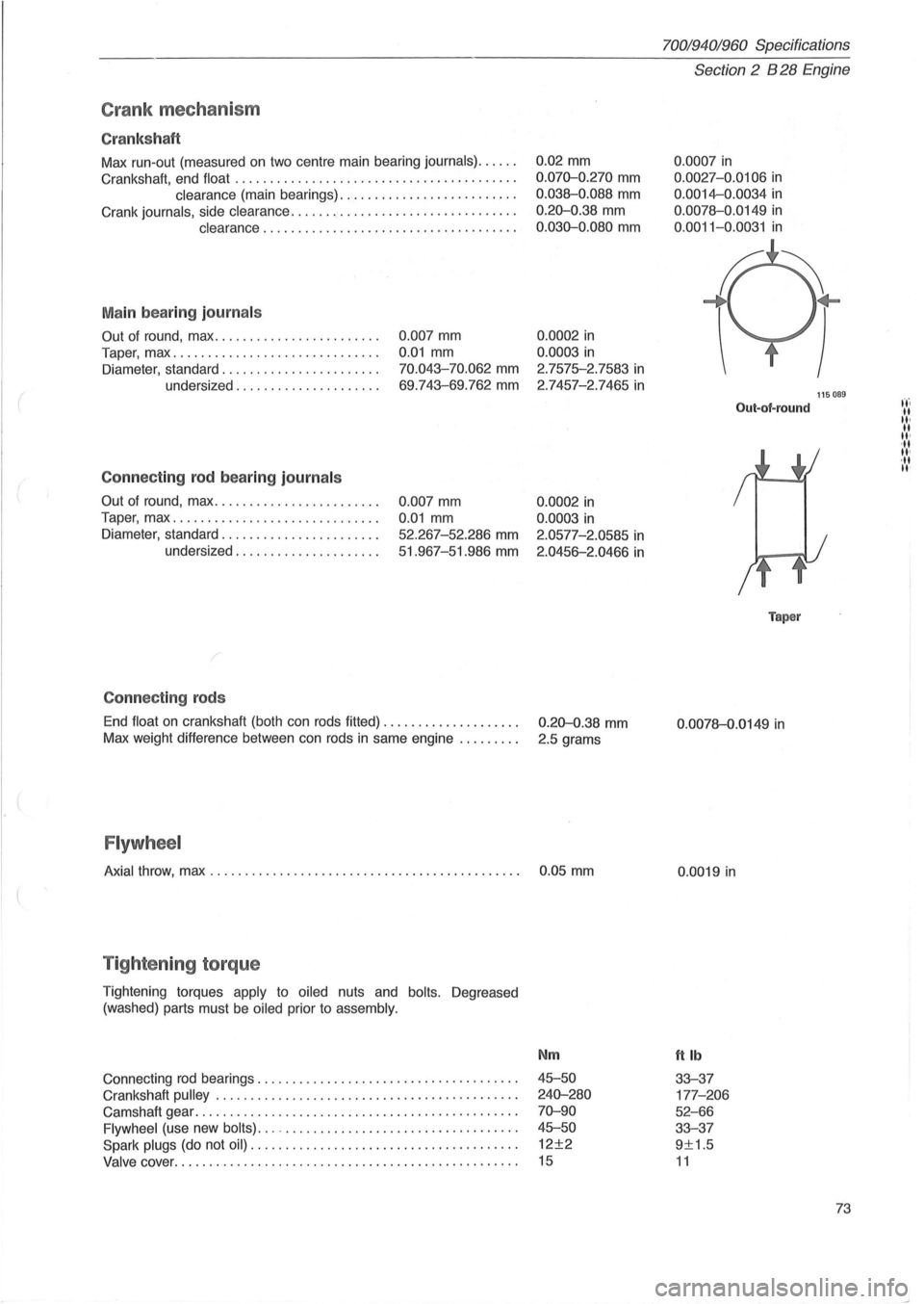
Crank mec ha ni sm
Cr ank sh aft
Max run-out (measured on two centre main bearing journals) ..... .
Crankshaft, end float
........................................ .
clearance (main bearings) ......................... .
Crank
journals, side clearance ...........•.................... .
clearance .................................... .
M ain bea rin g journ als
Out of round, max ....................... .
Taper, max
...... ....................... .
Diameter, standard ...
................... .
undersized
.................... .
Conne cting rod b ea ring journ als
Out of round, max ....................... .
Taper, max
............................. .
Diameter, standard
...................... .
undersized
.................... .
C onnec tin g rods
0 .007 mm
0.01 mm
70.043-70.062 mm
69 .743-69.762 mm
0.007 mm
0.01 mm
52.267-52 .286 mm
51.967-51.986 mm
End
float on crankshaft (both can rods fitted) ................... .
Max weight difference between can rods
in same engine ........ .
Flywh eel
0.02 mm
0 .070-0.270 mm
0.038-0.088 mm
0.20-0.38 mm
0 .030-0.080 mm
0.0002 in
0.0003 in
2.7575-2.7583 in
2 .7457-2.7465 in
0.0002 in
0.0003 in
2.0577-2.0585 in
2.0456-2.0466 in
0.20-0.38 mm
2.5 grams
Axial throw, max . . . . . . . . . . . . . . . . . . . . . . . . . . . . . . . . . . . . . . . . . . . . . 0 .05 mm
T ig hte nin g torq ue
Tightening torques apply to oiled nuts and bolts. Degreased
(washed) parts must be
oiled prior to assembly.
Connecting rod bearings ................. .......... ..... ..... .
Crankshaft
pulley . ........ .......... ........................ .
Camshaft gear
................................. ............. .
Flywheel (use new bolts) ... -................................. .
Spark plugs (do not oil) ...................................... .
Valve cover ......... .................................... .... .
Nm
45-50
240-280
70-90
45-50
12±2
15
70019401960 Specifications
Section 2 B 28 Engine
0 .0007 in
0.0027 -0.0106 in
0.0014-0.0034 in
0.0078-0 .0149 in
0 .0011-0.0031 in
Out-of-round
Taper
0 .0078-0.0149 in
0.0019 in
ttlb
33-37
177 -206
52-66
33-37
9±1.5
11
115089
73
t't'. -II II· II II' ,II II'
,II II'
Page 84 of 168
70019401960 Specifications
Section
2 B 28 Engine
Group 25 Intake and exhaust systems
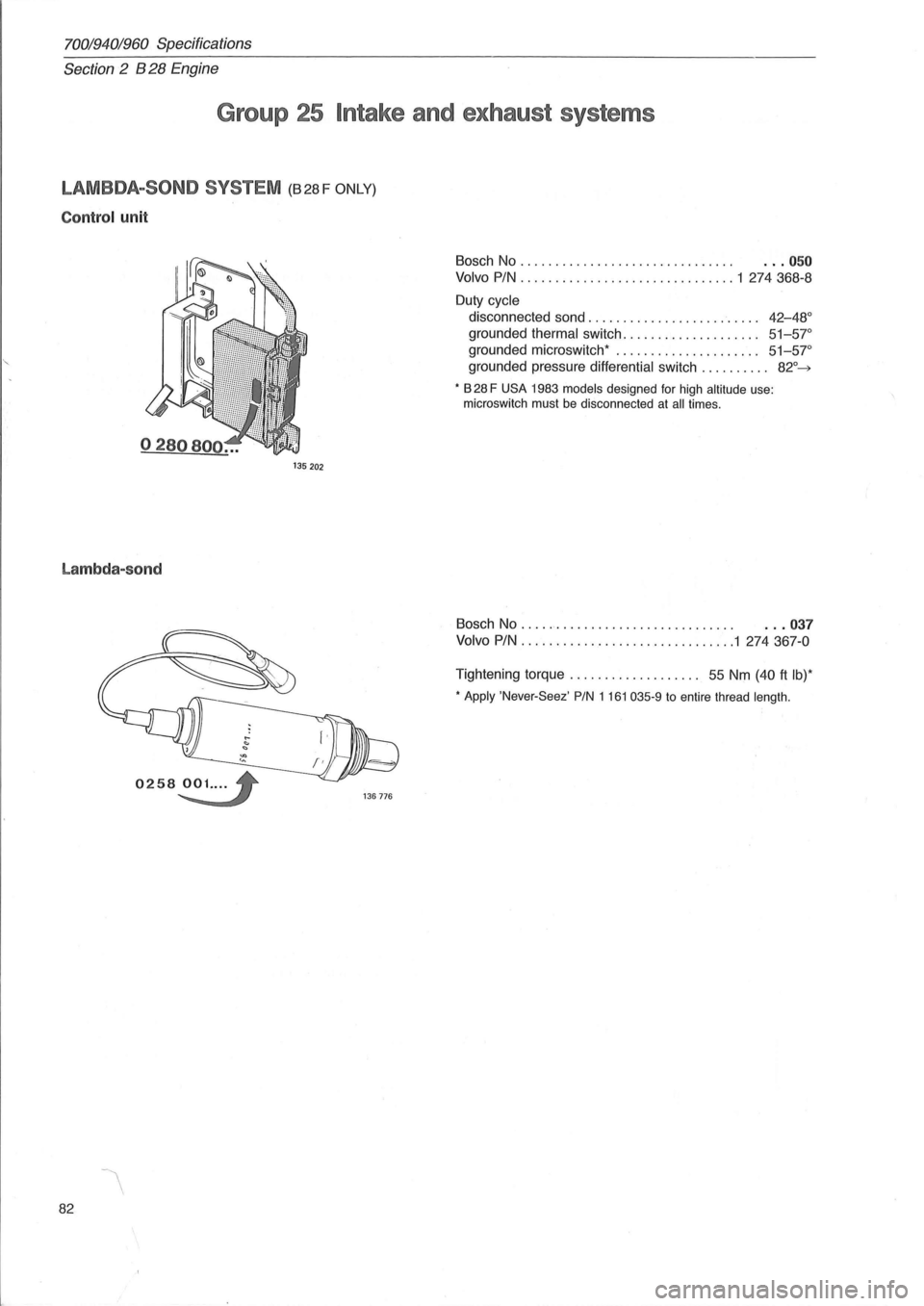
LAMBDA-SOND SYSTEM (B28F ONLY)
Control unit
135 202
Lambda-sond
82
Bosch No . . . . . . . . . . . . . . . . . . . . . . . . . . . . . . . . .. 050
Volvo PIN ............................... 1 274368-8
Duty cycle
disconnected sand. . . . . . . . . . . . . . . . . . . . . . . . .
42-48°
grounded thermal switch . . . . . . . . . . . . . . . . . . .. 51-57°
grounded microswitch* ..................... 51-57"
grounded pressure differential switch .......... 82°~
* B 28 F USA 1983 models designed for high altitude use:
microswitch must be disconnected at all times.
Bosch No . . . . .. . . . . . . . . . . . . . . . . . . . . . . . . . . .. 037
Volvo PIN ..................... .......... 1 274367-0
Tightening torque. . . . . . . . . . . . . . . . . .. 55 Nm (40 ft Ib)*
* Apply 'Never-Seez' PIN 1 161 035-9 to entire thread length.
Page 86 of 168
70019401960 Specifications
Section
2 B 28 Engine
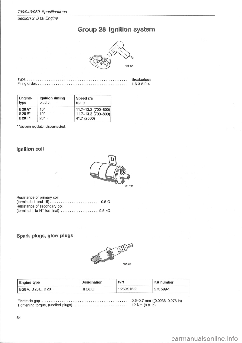
Group 28 Igni t ion system
Type. . . . . . . . . . . . . . . . . . . . . . . . . . . . . . . . . . . . . . . . . . . . . . . . . . . . . . . . Breakerless
Firing order. . . . . . . . . . . . . . . . . . . . . . . . . . . . . . . . . . . . . . . . . . . . . . . . . . 1-6 -3-5-2-4
E ngin e-
Ignition timing Spee d rls
type b.t.d.c .
(rpm)
8 28A*
10° 11.7 -13.3 (70D-800)
8 28 E* 10° 11.7 -13.3 (70D-800)
828F* 23° 41.7 (2500)
* Vacuum regulator disconnected.
Ig niti on coil
/
Resistance of primary coil
(terminals
1 and 15). . . . . . . . . . . . . . . . . . . . . . . . . .. 0.5 0
Resistance of secondary coil
(terminal
1 to HT terminal) . . . . . . . . . . . . . . . . . . .. 9.5 kO
Spark plugs , glo w p lugs
E ngin e type D
es ign ation
B28A, B28E, B28F HR6DC
1317S3
PIN
1269915-2 Kit
number
273599-1
Electrode gap .............................................. .
Tightening torque,
(unoiled plugs) ............................. .
0.6-0.7 mm ((0.0236-0.276 in)
12 Nm (9 ft Ib)
84
Page 88 of 168
70019401960 Specifications
Section 2 B 280' Engine .
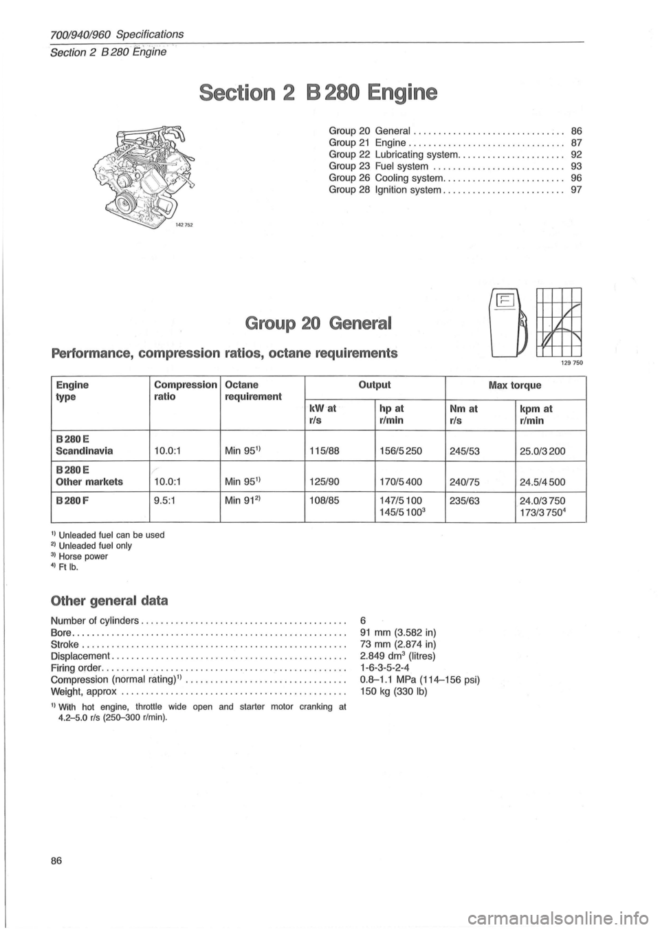
Section 2 B 280 Engine
Group 20 General . . . . . . . . . . . . . . . . . . . . . . . . . . . . . . . 86
Group
21 Engine..... ................. .......... 87
Group
22 Lubricating system. . . . . . . . . . . . . . . . . . . . .. 92
Group
23 Fuel system ........................ ... 93
Group
26 Cooling system ......................... 96
Group
28 Ignition system. . . . . . . . . . . . . . . . . . . . . . . .. 97
Group 20 General
Performance , compression ratios, octane requirements
Engine Compression Octane
type ratio
requirement
kW'a t
rls
B28 0E
Sca ndinavia 10.0:1 Min 951
) 115/88
B280 E r
Other markets 10 .0:1 Min 951
) 125/90
B280 F 9.5:1 Min 912
) 108/85
1) Unleaded fuel can be used 2) Unleaded fuel only 3) Horse power 4) Ft lb.
Other general data
Number of cylinders ................. ........................ .
Bore
.. ............................ ......................... .
Stroke ............................................... ...... .
Displacement
............................................... .
Firing order .
.................................. .' ............. .
Compression (normal
niting)l) ................................ .
Weight, approx ..
.................. ......................... .
1) With hot engine, throttle wide open and starter motor cranking at 4.2-5.0 rls (250-300 r/min).
86
Output
hp at
r/min
156/5250
170/5400
147/5100
145/5100
3
6
91 mm (3. 582 in)
73 mm (2.874 in)
2.849 dm3 (Iitres)
1 -6-3-5-2-4
Nm at
rls
245/53
240175
235/63
0.8-1 .1 MPa (114-156 psi)
150
kg (330 Ib)
IL ~
j.
~ 1'
129 750
Max torque
kpm at
rlmin
25.0/3200
24.5/4500
24.0/3750
173/37504
Page 92 of 168
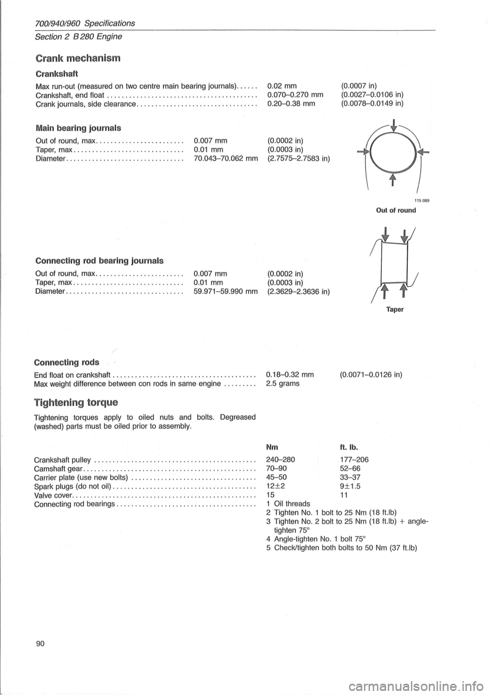
70019401960 Specifications
Section
2 B 280 Engine
Crank mechanism
Cranks haft
Max run-out (measured on two centre main bearing journals) ..... .
Crankshaft, end
float ........................................ .
Crank
journals, side clearance ................................ .
Main bearing journal s
Out of round, max. ; ..................... .
Taper, max
............................. .
Diameter
............................... .
Connecting rod bearing journal s
Out of round, max ....................... .
Taper,
max " ............................. .
Diameter
............................ ... .
Connecting rods
0.007 mm
0.01 mm
70.043-70.062 mm
0.007 mm
0.01 mm
59.971-59.990 mm
End float on crankshaft ...................................... .
Max weight difference between can rods
in same engine ........ .
Tightening torque
Tightening torques apply to oiled nuts and bolts. Degreased
(washed) parts must
be oiled prior to assembly.
Crankshaft pulley ........................ ................... .
Camshaft gear
.............................................. .
Carrier
plate (use new bolts) ................................. .
Spark
plugs (do not oil) .. .................................... .
Valve cover ........................................... ...... .
Connecting
rod bearings ..................................... .
90 0.02
mm
0.070-0.270 mm
0.20-0.38 mm
(0.0002 in)
(0.0003
in)
(2.7575-2.7583
in)
(0.0007 in)
(0. 0027-0.0106 in)
(0.0078--0.0149
in)
115089
Out of round
(0.0002 in)
(0.0003 in)
(2.3629--2.3636 in)
0.18--0.32
mm
2.5 grams
Nm
240-280
70-90
45-50
12±2
15
1 Oil threads
Taper
(0.0071-0.0126 in)
ft. lb.
177-206
52-66
33-37
9±1.5
11
2 Tighten No.1 bolt to 25 Nm (18 ft.lb)
3 Tighten
No.2 bolt to 25 Nm (18 ft.lb) + angle
tighten 75°
4 Angle -tighten No. 1 bolt 75°
5 Check/tighten both bolts to 50 Nm (37 ft.lb)
Page 93 of 168
(
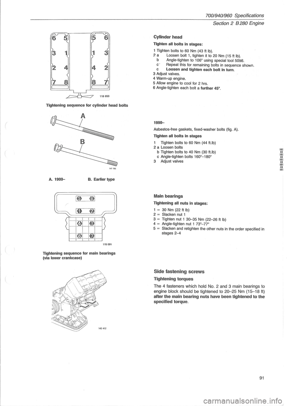
6
l1S 650
Tightening sequence for cylinder head bolts
147795
A. 1900-B. Ear lier type
115091
Tightening sequence for main bearings
(vi a lower crankcase)
7QOl9401960 Specifications
Section 2 B 280 Engine
Cylinder head
Tighten all bolts in stages:
1 Tighten bolts to 60 Nm (43 ft Ib). ? a Loosen bolt 1, tighten it to 20 Nm :(15 ft Ib). b Angle-tighten to 106° using special tool 5098. c' Repeat this for remaining bolts in sequence shown. c Loosen and tighte n each bolt in turn. 3 Adjust valves. 4 Warm-up engine.
5 Allow engine to cool for 2 hrs. 6 Angle-tighten each bolt a further 45°.
1990-
Asbestos-free gaskets, fixed-washer bolts (fig. A).
Tighten all bolts in stages
1 Tighten bolts to 60 Nm (44 ft.lb) 2 a Loosen bolts
b Tighten bolts to 40 Nm (30 ft.lb) c Angle-tighten bolts 160°-180° 3 Adjust valves
Main bearings
Tightening all nuts in stages:
1 = 30 Nm (22 ft Ib) 2 = Slacken nut 1 3 = Tighten nut 1 30-35 Nm (22-26 ft Ib) 4 = Angle-tighten nut 1 73°-77°
5 = Slacken and retighten the other nuts in the order specified in stages 2-4
Side fastening screws
Tightening torques
The 4 fasteners which hold No.2 and 3 main bearings to
engine block should be tightened to 20--25 Nm (15-18 tt)
after the main bearing nuts have been tightened to the
spec ified torque.
91
lit '\1 lit II lit .\1 lit ·11 III
Page 97 of 168
( ,
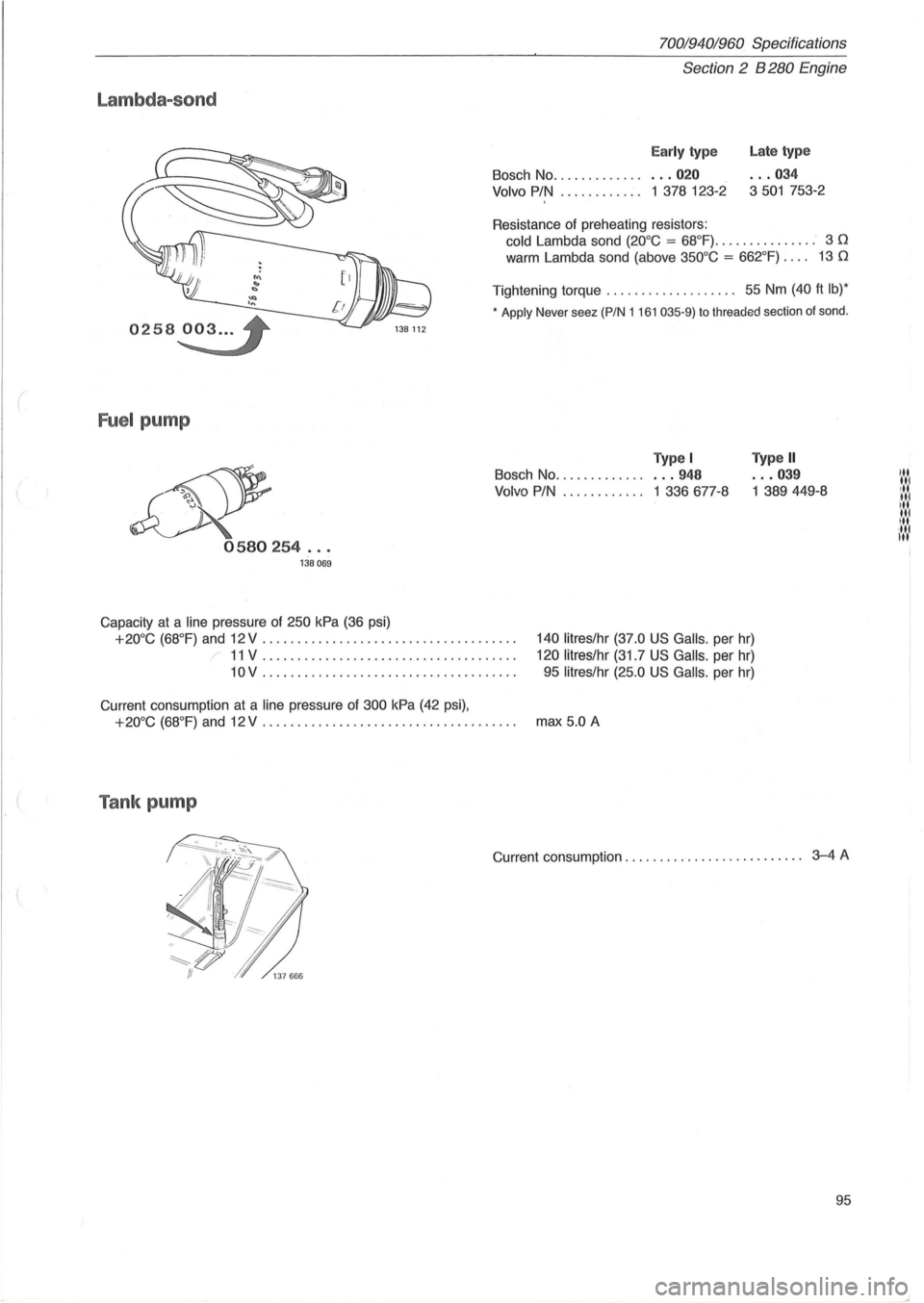
Lambda-sond
0258~ 138 112
Fuel pump
&' 0580254 ... 138069
Capacity at a line pressure of 250 kPa (36 psi)
70019401960 Specifications
Section 2 B 280 Engine
Early type
Bosch No ................ 020
Volvo PIN ............ 1 378 123-2
Resistance
of preheating resistors:
Late type
... 034
3501 753-2
cold Lambda sand (20°C = 68°F) ............... 3 n
warm Lambda sand (above 350°C = 662°F) . . .. 13 n
Tightening torque ....... ............ 55 Nm (40 ft Ib)*
* Apply Never seez (PIN 1 161 035-9) to threaded section of sond .
Type I
Bosch No ................ 948
Volvo PIN ............ 1 336 677-8
Type II
... 039
1 389449-8
+20°C (68°F) and 12 V .................................... . 140 litres/hr (37.0 US Galls. per hr)
120 litres/hr (31.7 US Galls . per hr)
95
litres/hr (25.0 US Galls. per hr)
11 V ........•............................
10V .. .................................. .
Current consumption
at a line pressure of 300 kPa (42 psi),
+20°C (68°F) and 12 V .................................... . max 5.0 A
Tank pump
Current consumption . . . . . . . . . . . . . . . . . . . . . . . . .. 3-4 A
95
'" III , II
NI' III ill ,II'
'"
)
Page 99 of 168
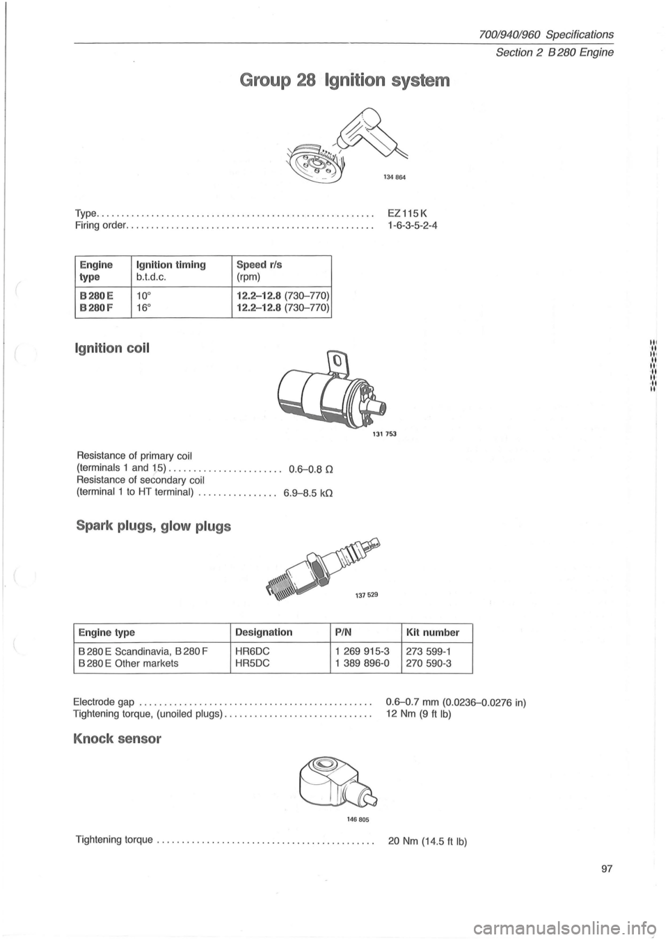
Group 28 Ignition system
~
~~ ~ 134864
Type ....................................................... .
EZ115K
1-6 -3-5 -2 -4
Firing
order ................................................. .
E ng in e
Ig niti on tim ing Speed rls
type b.t.d
.c. (rpm)
B280E 10° 12 .2-12 .8 (730-770)
B280 F 16° 12 .2-12.8 ( 7 30-770)
Ignit ion coil
Resistance of primary coil
(terminals
1 and 15) . . . . . . . . . . . . . . . . . . . . . . . 0.6-0.8 n
Resistance of secondary coil
(terminal
1 to HT terminal) ..... . . . . . . . . . .. 6 .9-8.5 kn
Spark plugs, glow plugs
Eng in e type Des
ig nation
B
280 E Scandinav ia , B 280 F HR6DC
B
280 E Other markets HR5DC
1317~
PIN
1 269915-3
1
389896-0
Kit num ber
273599-1
270590-3
70019401960 Specifications
Section
2 B 280 E ngine
Electrode gap . . . . . . . . . . . . . . . . . . . . . . . . . . . . . . . . . . . . . . . . . . . . . . . 0.6-0.7 mm (0.0236-0.0276 in)
Tightening torque, (unoiled plugs). . . . . . . . . . . . . . . . . . . . . . . . . . . . . . 12 Nm (9 ft Ib)
Knock sensor
14 6 805
Tightening torque. . . . . . . . . . . . . . . . . . . . . . . . . . . . . . . . . . . . . . . . . . . . 20 Nm (14.5 ft Ib)
97
III ... III II
II' ... II' ·11 II