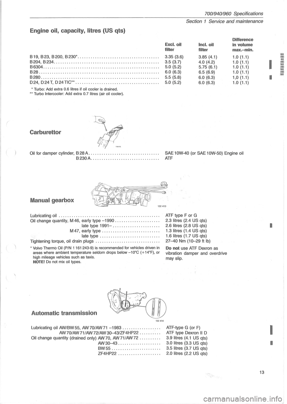
1982 VOLVO 700 engine oil capacity
[x] Cancel search: engine oil capacityPage 15 of 168
(
70019401960 Specifications
Section 1 Service and maintenance
Engine oil, capacity, litres (US qts )
Difference
Excl. oil Incl. oil in volum e filter
filter max.-min.
819,823,8200,8230· .................. ................... .
3.35 (3.6)
3.85 (4.1) 1.0(1.1)
8204,8234 ............................ .................... . 3.5 (3.7) 4.0 (4.2) 1.0 (1.1) 86304 ............................................. ........ . 5.0 (5.2) 5.75 (6.1) 1.0 (1.1)
828 ....................................................... . 6 .0 (6 .3) 6.5 (6.9) 1.0 (1.1)
8280 .......................... ............................ . 5.5 (5.8) 6.0 (6.3) 1,0(1.1)
024,024 T, 024 TiC·· ....................... ............... . 5 .0 (5.2) 6 .0 (6.3) 1.0(1.1)
• Turbo: Add extra 0.6 litres if oil cooler is drained . .. Turbo Intercooler : Add extra 0.7 litres (air oil cooler) .
Carburettor
Oil for damper cylinder , 828 A. . . . . . . . . . . . . . . . . . . . . . . . . . . . . . . . . SAE 10W-40 (or SAE 10W-50) Engine oil
8230A................................ ATF
Manual gearbox
Lubricating oil ............................ .................. .
Oil change quantity, M 46, early type -1990 .................... .
late type 1991-..................... .
M
47, early type ...................... . ... .
late type ........................... .
Tightening torque, oil drain
plugs ............................. .
• Volvo Thermo Oil (PIN 1 161 243-9) is recommended for vehicles driven in areas where ambient temperature seldom drops below -10°C (+14°F) , or
high mileage vehicles such as taxis . NOTE! Do not mix oil types .
Automat ic transmission
132414
Lubricating oil AW/8W55, AW70/AW71 -1983 ................. .
AW70/AW 71/AW721AW
30-43/ZF4HP22 ......... .
Oil change quantity (drained only) AW 70, AW 71 lAW 72 ......... .
AW30-43 ................... .
8W55 ............ .......... .
ZF4HP22 ................... . ATF
type F or G
2.3
litres (2.4 US qts)
2.6
litres (2.8 US qts)
1 .3
litres (1.4 US qts)
1.6
litres (1.7 US qts)
27-40 Nm (10-29 ft Ib)
Do not use ATF Oexron as
vibration damper and overdrive
may
slip.
ATF -type G (or F)
ATF type Oexron II 0
3.9 litres (4.1 US qts)
3 .0 litres (3.3 US qts)
3.5
litres (3.7 US qts)
2.0 litres (2.2 US qts)
13
Itt liN
I
III
:1:1:1
I
11.'.1
I
I
I
Page 22 of 168
70019401960 Specifications
Section 2 B
19, B 23 Engines
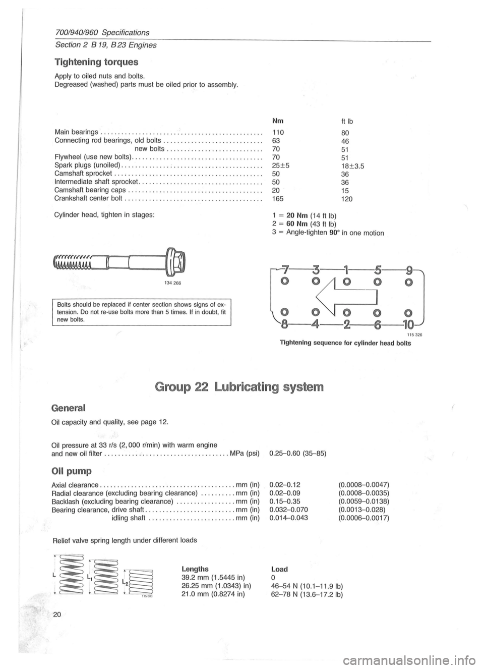
Tightening torques
Apply to oiled nuts and bolts.
Oegreased (washed) parts must be oiled prior to assembly.
Main bearings ....................... ' ....................... .
Connecting rod bearings,
old bolts ............................ .
new
bolts ......... .................. .
Flywheel (use new bolts) ..................................... .
Spark
plugs (unoiled) .............. ; ......................... .
Camshaft sprocket
............... ........................... .
Intermediate shaft sprocket ................................. .. .
Camshaft bearing caps .
............................ ......... .
Crankshaft center
bolt ....................................... .
Cylinder head , tighten in stages:
134266
Bolts should be replaced if center section shows signs of extension. Do not re-use bolts more than 5 times . If in doubt, fit
new bolts.
Nm
110
63
70
70
25±5
50
50 20
165
1 = 20 Nm (14 ft Ib)
2 = 60 Nm (43 ft Ib)
ft Ib
80
46
51
51
18±3.5
36
36 15
120
3 = Angle-tighten 900 in one motion
'7--3---
o 0
000
8-4-2-
--9
o
115326
Tightening sequence for cylinder head bolts
Group 22 Lubricating system
General
Oil capacity and quality, see page 12.
Oil pressure at 33 rls (2,000 r/min) with warm engine
and new
oil filter ...... .............................. MPa (psi) 0.25-0.60 (35-85)
Oil pump
Axial clearance .................. ..................... mm (in)
Radial clearance (excluding bearing clearance) .......... mm (in)
Backlash (excluding bearing clearance) ................. mm (in)
Bearing clearance, drive shaft
.......................... mm (in)
idling shaft ..... ........... .......... mm (in)
Relief valve spring length under different loads
~~~ 115083
20
Lengths
39.2 mm (1.5445 in)
26.25 mm (1.0343) in)
21.0 mm (0.8274 in)
0.02-0.12
0.02-0.09
0.15-0.35
0.032-0.070
0.014-0.043
Load
o
(0.0008-0 .0047)
(0.0008-0.0035)
(0.0059-0.0138)
(0.0013-0. 028)
(0.0006-0.0017)
46-54 N (10.1-11.9 Ib)
62 -78 N (13.6-17.2 Ib)
(
Page 44 of 168
70019401960 Specifications
Section 2 B 200, B 230 Engines
8204/234
Cam carrier (centre fasteners) . . . . . . . . . . . . . . . . . . . . . . . . . . . . . . . . . 20 15
Oil pump. . . . . . . . . . . . . . . . . . . . . . . . . . . . . . . . . . . . . . . . . . . . . . . . . . . . 11 7
Oil pump, inlet ..... , . . . . . . . . . . . . . . . . . . . . . . . . . . . . . . . . . . . . . . . . . 11 8
Oil pump -pulley, step 1 ..................................... 20 15
step 2 .......... . . . . . . . . . . . . . . . . . . . . . . . . . . . angle-tighten 60 °
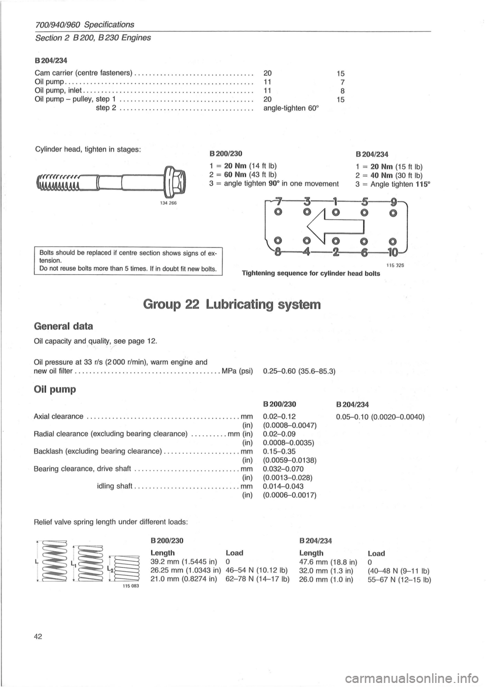
Cylinder head , tighten in stages : 8200/230
1 = 20 Nm (14 ft Ib)
2 = 60 Nm (43 ft Ib)
3 = angle tighten 90° in one movement
8204/234
1 = 20 Nm (15 ft Ib)
2 = 40 Nm (30 ft Ib)
3 = Angle tighten 115°
134 266 ~'--~3---1---5,---w9'~
Bolts should be replaced if centre section shows signs of ex
tension.
o ~O
o O~ 0
-~8,---..... 4-2 6 1
ns 125 Do not reuse bolts more than 5 times . If in doubt fit new bolls . Tightening sequence for cylinder head bolts
Group 22 Lubricating system
General data
Oil capacity and quality, see page 12.
Oil pressure at 33 rls (2000 rim in), warm engine and
new oil
filter ........ ; ............................... MPa (psi) 0.25-0.60 (35.6-85.3)
Oil pump
8200/230
0.02-0. 12
(0.0008-0.0047)
0 .
02-0.09
0.0008-0.0035)
0 .
15-0.35
(0.0059-0.0138)
0 .
032-0.070
(0.0013-0.028)
0 .
014-0.043
(0.0006-0.0017)
8204/234
Axial clearance ................ ... ....................... mm
(in)
Radial clearance (excluding bearing clearance) . ......... mm (in)
(in)
Backlash (excluding bearing clearance) ..................... mm
(in)
Bearing clearance , drive shaft
............................. mm
(in)
idling shaft .................... ......... mm
Relief valve spring length under different loads:
115083
42
8200/230
Length
39.2 mm (1.5445 in)
26.25 mm (1. 0343 in)
21.0 mm (0.8274 in) (in)
Load
o
46-54 N (10.12 Ib)
62-78 N (14-17 Ib)
0.05-0.
10 (0.0020-0.0040)
8204/ 234
Length
47.6 mm (18.8 in)
32.0 mm (1.3 in)
26 .0 mm (1.0 in)
Load
o
(40-48 N (9-11 Ib)
55-67 N (12-15 Ib)
Page 76 of 168
70019401960 Specifications
Section
2 B 28 Engine
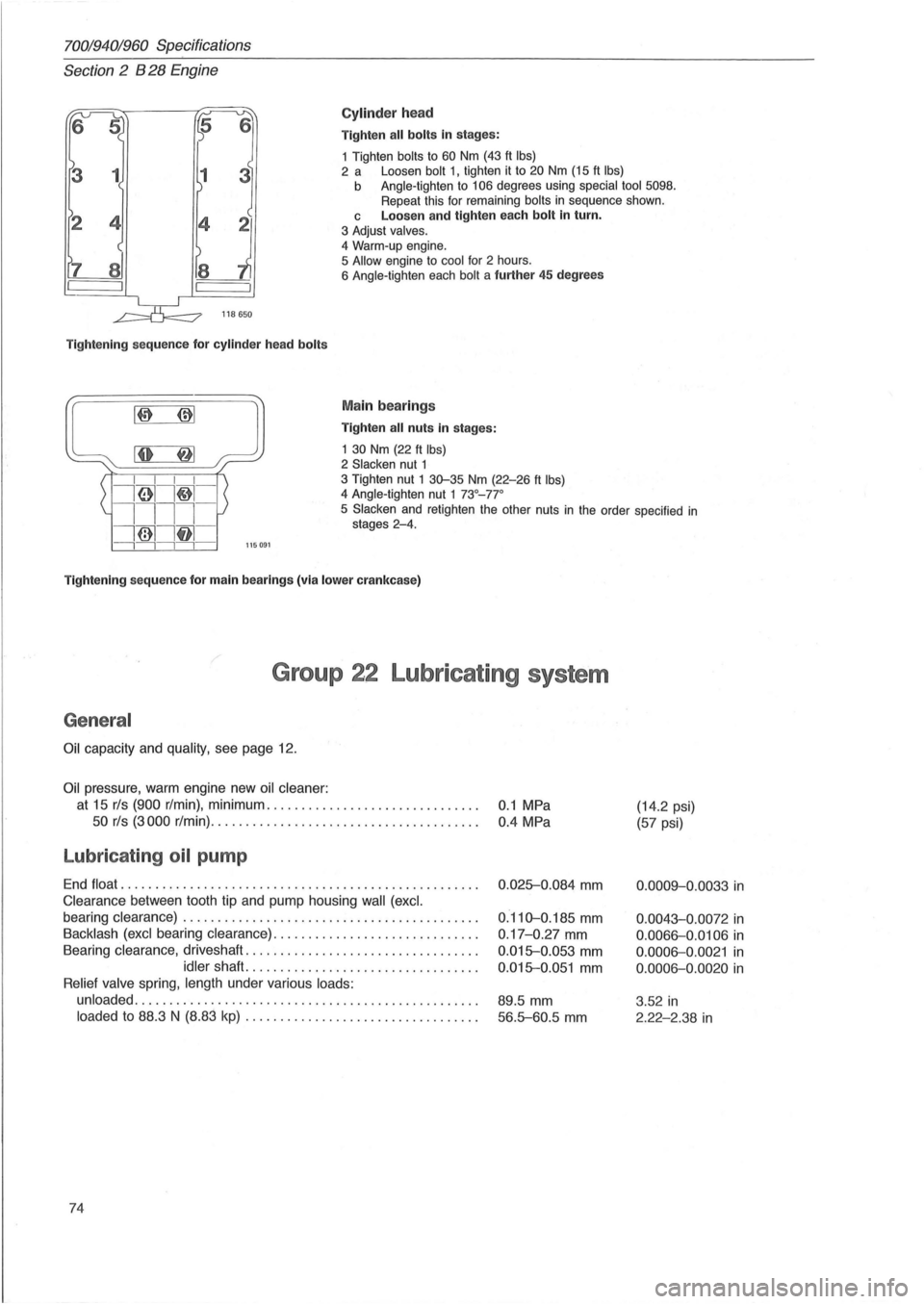
Cylinder head
Tighten all bolts in stages:
1 Tighten
bolts to 60 Nm (43 ft Ibs) 2 a Loosen bolt 1, tighten it to 20 Nm (15 ft Ibs) b Angle-tighten to 106 degrees using special tool 5098. Repeat this for remaining bolts in sequence shown.
118650
Tightening sequence for cylinder head bolts
L~~::~:~' ~I ~: I I I I
i61I~-
c Loosen and tighten each bolt in turn.
3 Adjust valves.
4
Warm-up engine.
5 Allow engine to cool for 2 hours.
6 Angle-tighten each bolt a further 45 degrees
Main bearings
Tighten all nuts in stages:
1
30 Nm (22 ft Ibs) 2 Slacken nut 1 3 Tighten nut 1 30-35 Nm (22-26 ft Ibs) 4 Angle-tighten nut 1 73°_77 °
1111-
i@1lf11 -
5 Slacken and retighten the other nuts in the order specified in stages 2-4.
---,---,---,---,-115091
Tightening sequence for main bearings (via lower crankcase)
Group 22 Lubricating system
General
Oil capacity and quality, see page 12.
Oil pressure, warm engine new oil cleaner:
at 15 rls (900 r/min), minimum .............................. .
50 rls (3000 r/min) .......... ....... ......... ............ .
Lubricating oil pump
End float ................................................... .
Clearance between tooth tip and pump housing wall (excl.
bearing clearance) .......................................... .
Backlash (excl bearing clearance) ................ ............. .
Bearing
clearance, driveshaft ................................. .
idler shaft. ................................ .
Relief valve spring, length under various loads:
unloaded
................................................. .
loaded to 88.3 N (8.83 kp) ............ ... .... .............. .
74
0.1 MPa
0.4 MPa
0 .
025-0.084 mm
0.110-0.185 mm
0 .17-0.27 mm
0.015-0.053 mm
0.015-0.051 mm
89.5 mm
56.5-60.5 mm
(14.2 psi)
(57 psi)
0.0009-0.0033 in
0.0043-0.0072 in
0.0066-0.0106 in
0 .0006-0.0021 in
0.0006-0.0020 in
3 .52 in
2.22-2.38 in
Page 94 of 168
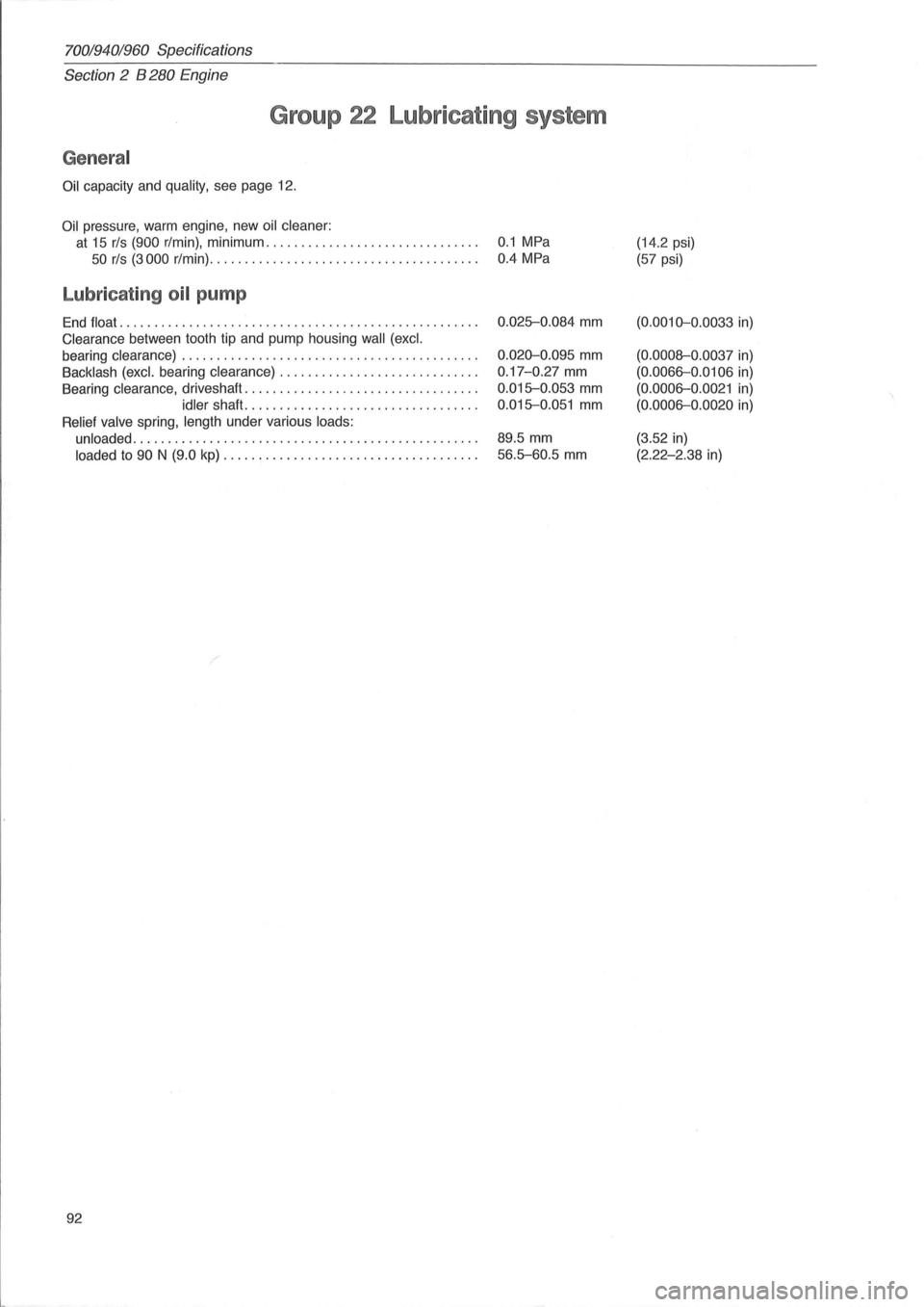
70019401960 Specifications
Section 2 B 280 Engine
Group 22 Lubricating system
General
Oil capacity and quality, see page 12.
Oil pressure, warm engine , new oil cleaner:
at 15 rls (900 r/min), minimum. . . . . . . . . . . . . . . . . . . . . . . . . . . . . . . 0.1 MPa
50 rls (3000 r/min). . . . . . . . . . . . . . . . . . . . . . . . . . . . . . . . . . . . . . . 0.4 MPa
Lubricating oil pump
End float ...... ........................ ..................... .
Clearance between tooth tip and pump housing wall (excl.
bearing clearance) .
......................................... .
Backlash (excl. bearing clearance) ............................ .
Bearing clearance , driveshaft ....
............................. .
idler shaft ................................. .
Relief valve spring, length under various loads:
unloaded
..................... ................. ........... .
loaded to 90 N (9.0 kp) .................................... .
92
0.025-0.084 mm
0.020-0.095 mm
0.17 -0.27 mm
0.015-0.053 mm
0.015-0.051 mm
89.5 mm
56.5-60.5 mm
(14.2 psi)
(57 psi)
(0.0010-0 .0033 in)
(0.0008-0 .0037 in)
(0.0066-0 .0106 in)
(0.0006-0 .0021 in)
(0.0006-0.0020 in)
(3.52 in)
(2.22-2.38 in)
Page 116 of 168
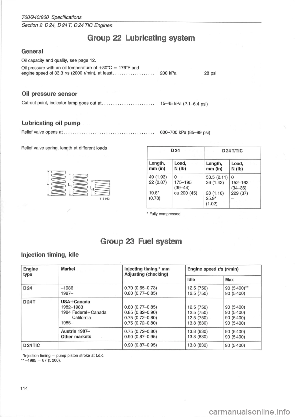
70019401960 Specifications
Section 2 024, 024 T, 024 TIC Engines
Group 22 Lubricating system
General
Oil capacity and quality, see page 12.
Oil pressure with an oil temperature of +80°C = 176°F and
engine speed of 33.3 rls (2000 r/min) , at least. . . . . . . . . . . . . . . . . . . 200 kPa 28 psi
Oil pressure sensor
Cut-out point, indicator lamp goes out at. ...................... . 15-45 kPa (2.1-6.4 psi)
Lubricating oil pump ,
Relief valve opens at ........................................ . 600-700 kPa (85-99 psi)
Relief valve spring, length at different loads 024 o 24TfTlC
Length, Load,
Length, Load,
mm (in) N (Ib) mm (in) N (Ib)
49 (1.93) 0 53.5 (2.11) 0 22 (0.87)
175-195
36 (1.42) 152-162
(39-44) (34-36)
19.8 * ca 200 (45)
28(1.10) 229 (37)
115 083 (0.78) 25.9 * -
(1.02)
* Fully compressed
Group 23 Fuel system
Injection timing, idle
Engin e Market
type
024 -1986
1987-
024T USA+Can ada
1982-1983
1984
Federal + Canada
California
1985-
Austr ia 1987 -
Other markets
024TIC
*Injection timing = pump piston stroke at t.d .c . ** - 1985 = 87 (5200).
114
Injecting timing, * mm
Engine speed rls (r/min)
Adjusting (check ing)
Idle Max
0.70 (0.65-0 .73)
12.5 (750) 90 (5400)* *
0.80 (0.77-0.85) 12.5 (750) 90 (5400)
0.80
(0.77-0 .85) 12.5 (750) 90 (5400)
0.85 (0.82-0 .90) 12.5 (750) 90 (5400)
0.75 (0.72- 0 .80) 12.5 (750) 90 (5400)
0.75 (0.72-0 .80) 13.8 (830) 90 (5400)
0.75 (0.72-0.80) 13.8 (830) 90 (5400)
0 .90
(0.87-0 .95) 13.8 (830) 90 (5400)
0.90
(0.87-0.95) 13. 8 (830) 90 (5400)
Page 142 of 168
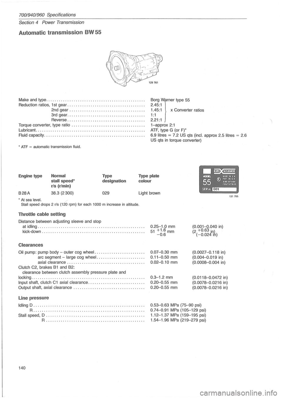
70019401960 Specifications
Section 4 Power Transmission
Automat ic transmission BW 55
Make and type .. ............................................ .
Reduction ratios, 1 st gear ..
................. ................. .
2nd gear
................................... .
3rd gear
................... ................. .
Reverse
.................................... .
Torque converter, type ratio
................................ .. .
Lubricant.
........................... ....................... .
Fluid capacity .................... ........................... .
* ATF = automatic transmission fluid.
1.45:1 x Converter ratios
Borg
Wirner type
55
2.45 :1
1 : 1
2.21 : 1
1-approx 2:1
ATF, type G (or F)*
6.9
litres = 7.2 US qts (inc!. approx 2.5 litres = 2 .6
US qts in torque converter)
.~ Engine type Normal
stall speed*
rls (r/min)
Type
designation
Type plate
colour
....... WAOIIHUH
55 e:> ~~D ~~~I~ f'"OUTUTAUS
B28A 38.3 (2300) 029 SERIAl~ Light brown 131755 * At sea level.
Stall speed drops 2 rls (120 rpm) for each 1000 m increase in altitude .
Throttle cable setting
Distance between adjusting sleeve and stop
at idling .................................................. .
kick -down
........................ ........................ .
C leara nces
Oil pump: pump body -outer cog wheel ....................... .
arc segment -
large cog wheel ...................... .
axial clearance .................................... .
Clutch C2, brakes B1 and B2:
clearance between
clutch assembly pressure plate and
locking ..................................................... .
Input shaft, clutch C1 axial clearance .......................... .
Output shaft,
axial clearance ................................. .
Line pressure
Idling D .................................................... .
R ..................... .... ........................... .
Stall speed, D .................. .............. ...... ........ .
R .............................................. .
140 0.25-1
.0
mm 51 +1.6mm -0.6
0.07-0.30 mm
0.11-0 .50 mm
0.02-0.10 mm
0.3-1 .2 mm
0.20-0 .55 mm
0.20-0.55 mm
(0.001-0.040 in) (2 +0.63 in) (-0.024Ih)
(0.0027-0.118 in)
(0.004-0 .019 in)
(0.0008-0.004 in)
(0.0118-0 .0472 in)
(0.0078-0.0216 in)
(0.0078-0.0216 in)
0.53-0.63 MPa (75-90 psi)
0.74-0.91 MPa (105-129 psi)
1 .12 -1.37
MPa (159-195 psi)
1.54-1.96
MPa (219-279 psi)