1982 VOLVO 700 torque
[x] Cancel search: torquePage 100 of 168
70019401960 Specifications
Section 2 B 6304 Engine
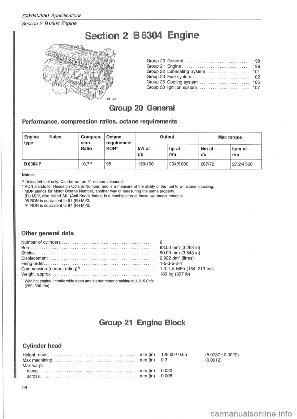
Section 2 B 6304 Engine
Group 20 General.... . . . . . . . . . . . . . . . . . . . . . . . . .. 98
Group 21 Engine............................... 98
Group
22 Lubricating System. . . . . . . . . . . . . . . . . . .. 101
Group 23 Fuel system . . . . . . . . . . . . . . . . . . . . . . . . .. 102
Group 26 Cooling system . . . . . . . . . . . . . . . . . . . . . .. 106
Group 28 Ignition system . . . . . . . . . . . . . . . . . . . . . . . . 107
Group 20 General
Performance , compression ratios, octane requirements
Engine Notes Compres-Octane
Output
type sion
requirement
Ratio
RON· kWat hp at Nm at
rls rim
rls
B6304F 10,71
) 95 150/100 204/6000 267172
Notes:
1) Unleaded fuel only. Can be run on 91 octane unleaded . • RON stands for Research Octane Number, and is a measure of the ability of the fuel to withstand knocking. MON stands for Motor Octane Number, another way of measuring the same property .
(R+M)/2, also called AKI (Anti Knock Index) is a combination of these two measurements . 95 RON is equivalent to 91 (R+M)/2. 91 RON is equivalent to 87 (R+M)/2 .
Other general data
Number of cylinders ......................................... .
Bore .
.................................................... .. .
Stroke .......................................... .......... . .
Displacement ......................... ................ ...... .
Firing order
............................................... .. .
Compression
(normal rating) 1) • ••••• ••••••••••••••••• •.••••••.•
Weight, approx ............................................. .
1) With hot engine, throttle wide open and starter motor cranking at 4.2-5.0 rls (250-300 rIm)
6
83.00 mm (3.268 in)
90 .00 mm (3.543 in)
2.922 dm3 (Iitres)
1-5 -3-6-2 -4
1 .3-1 .5 MPa (184-213 psi)
180 kg (397 Ib)
Group 21 Engine Block
Cylinder head
Max torque
kpm at
rim
27.214300
Height, new ............................... ........... mm (in) 129 .00±0.05
Max machining .............. ......................... mm (in) 0.3
(5.0787±0.0020)
(0.0012)
Max warp:
along ......... .... ................................. mm (in) 0.020
across .................................. ...... ..... mm (in) 0 .008
98
Page 102 of 168
70019401960 Specifications
Section 2 B 6304 Engine
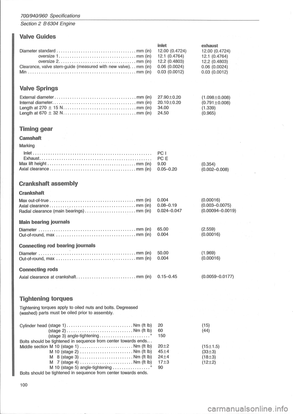
Valve Guides
Diameter standard .................................... mm (in)
oversize 1
................................... mm (in)
oversize 2
...................... ............. mm (in)
Clearance, valve stem-guide (measured with new valve) ... mm (in)
Min .
................................................ mm (in)
Valve Springs
External diameter ..................................... mm (in)
Internal diameter ...................................... mm (in)
Length at
270 ± 15 N ................................. mm (in)
Length at
670 ± 32 N ................................. mm (in)
Timing gear
Cams haft
Marking
Inlet ..................................................... .
Exhaust
.................................................. .
Max
lift height ................... ..................... mm (in)
Axial clearance ....................................... mm (in)
Crankshaft assembly
Crankshaft
Max out-ol-true ...................................... . mm (in)
Axial clearance ....................................... mm (in)
Radial clearance (main bearings) ....................... mm (in)
Main bearing journals
Diameter ............................................ mm (in)
Out-ol-round, max
.................................... mm (in)
Connecting rod bearing journ als
Diameter ................................... ......... mm (in)
Out-aI-round, max
.................................... mm (in)
Connecting rods
Axial clearance at crankshaft ........................... mm (in)
Tightening torques
Tightening torques apply to oiled nuts and bolts. Degreased
(washed) parts must
be oiled prior to assembly.
Cylinder
head (stage 1) .............................. Nm (ft Ib)
(stage 2) .............................. Nm (ft Ib)
(stage 3) angle -tightening ....................... 0
Bolts should be tightened in sequence Irom center towards ends .. .
Middle section M 10 (stage 1) ........................ Nm (ft Ib)
M 10 (stage 2) ........................ Nm (ft Ib)
M 8 (stage 3) ........................ Nm (It Ib)
M 7 (stage 4) ........................ Nm (It Ib)
M 10 (stage 5) angle -tightening ................. 0
Bolts should be tightened in sequence Irom center towards ends.
100
inlet
12.00 (0.4724)
12.1 (0.4764)
12.2 (0.4803)
0.06 (0.0024)
0.03 (0.0012)
27.90±0.20
20.10±0.20
34.00
24.50
PC I
PC E
9.00 0.05-0.20
0.004
0.08-0.19
0.024-0.047
65.00 0.004
50.00 0.004
0.15-0.45
20
60 150
20±2
45±4
24±4
17±3
90
exhaust
12.00 (0.4724)
12.1 (0.4764)
12.2 (0.4803)
0.06 (0.0024)
0.03 (0.0012)
(1.098±0.008)
(0.791 ±0.008)
(1.339)
(0.965)
(0.354)
(0.002-0.008)
(0. 00016)
(0.003-0.0075)
(0.00094-0.0019)
(2.559)
(0.00016)
(1.969)
(0.00016)
(0.0059-0 .0177)
(15)
(44)
(15±1.5)
(33±3)
(18±3)
(12±2)
Page 106 of 168
70019401960 Specifications
Section
2 B 6304 Engine
I
150425
o 580 464 ...
145791
145792
Sil
104
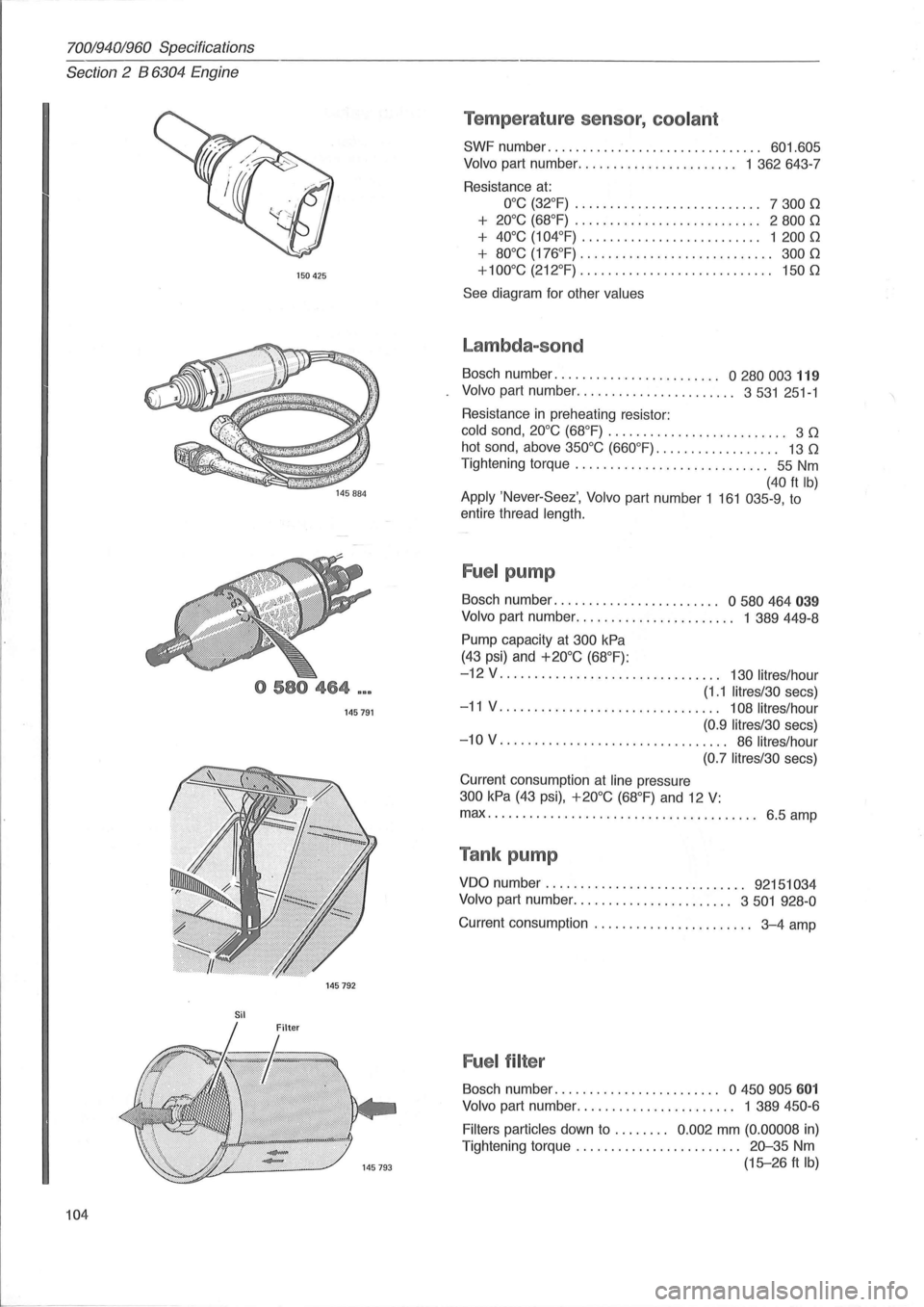
Temperature sensor, coolant
SWF number. . . . . . . . . . . . . . . . . . . . . . . . . . . . . .. 601.605
Volvo part number ....................... 1 362643-7
Resistance
at:
O°C (32°F) . . . . . . . . . . . . . . . . . . . . . . . . . .. 7 300 0
+ 20°C (68°F) . . . . . . . . . . . . . . . . . . . . . . . . . .. 2 800 0
+ 40°C (104°F) . . . .. . . .. . .. . .. . . . . . . . . . .. 1 200 0
+ 80°C (176°F) . . . . . . . . . . . . . . . . . . . .. . . . . . .. 300 0
+100°C (212°F)
............................ 1500
See diagram for other values
Lambda-sond
Bosch number. . . . . . . . . . . . . . . . . . . . . . .. 0 280 003 119
Volvo part number ....................... 3531 251-1
Resistance
in preheating resistor:
cold sand, 20°C (68°F) . . . . . . . . . . . . . . . . . . . . . . . . .. 3 0
hot sand, above 350°C (660°F). . . . . . . . . . . . . . . . .. 13 0
Tightening torque . . . . . . . . . . . . . . . . . . . . . . . . . . .. 55 Nm
(40 ft Ib) Apply 'Never-Seez', Volvo part number 1 161 035-9, to
entire thread
length.
Fuel pump
Bosch number. . . . . . . . . . . . . . . . . . . . . . .. 0 580 464 039
Volvo part number. . . . . . . . . . . . . . . . . . . . . .. 1 389449-8
Pump capacity at 300 kPa
(43 psi) and +20°C (68°F):
-12 V . . . . . . . . . . . . . . . . . . . . . . . . . . . . . . .. 130 lit res/hour
(1.1 litres/30 secs)
-11 V. . . . . . . . . . . . . . . . . . . . . . . . . . . . . . .. 108 litres/hour
(0.9 Iitres/30
secs)
-10 V. . . . . . . . . . . . . . . . . . . . . . . . . . . . . . . .. 86 litres/hour
(0.7 litres/30
secs)
Current consumption
at line pressure
300 kPa (43 psi), +20°C (68°F) and 12 V:
max ................................ ....... 6.5 amp
Tank pump
VDO number. . . . . . . . . . . . . . . . . . . . . . . . . . . .. 92151034
Volvo
part number ....................... 3501 928-0
Current consumption . . . . . . . . . . . . . . . . . . . . . .. 3-4 amp
Fuel filter
Bosch number. . . . . . . . . . . . . . . . . . . . . . .. a 450 905 601
Volvo part number. . . . . . . . . . . . . . . . . . . . . .. 1 389 450-6
Filters particles
down to . . . . . . .. 0.002 mm (0.00008 in)
Tightening torque . . . . . . . . . . . . . . . . . . . . . .
.. 20-35 Nm
(15-26 ft Ib)
Page 109 of 168
(
70019401960 Specifications
Section
2 B 6304 Engine
Group 28 Ignition System
Type. . . . . . . . . . . . . . . . . . . . . . . . . . . . . . . . . . . . . . . . . . . . . . . . . . . . . . . . Motronic 1.8
Firing sequence . . . . . . . . . . . . . . . . . . . . . . . . . . . . . . . . . . . . . . . . . . . . . . 1-5-3-6-2-4
Ignition timing at 12.5 rls (750 rim). . . . . . . . . . . . . . . . . . . . . . . . . . . . . 5 °
Made in Germany @
150365
150431
148680
COMPONENTS
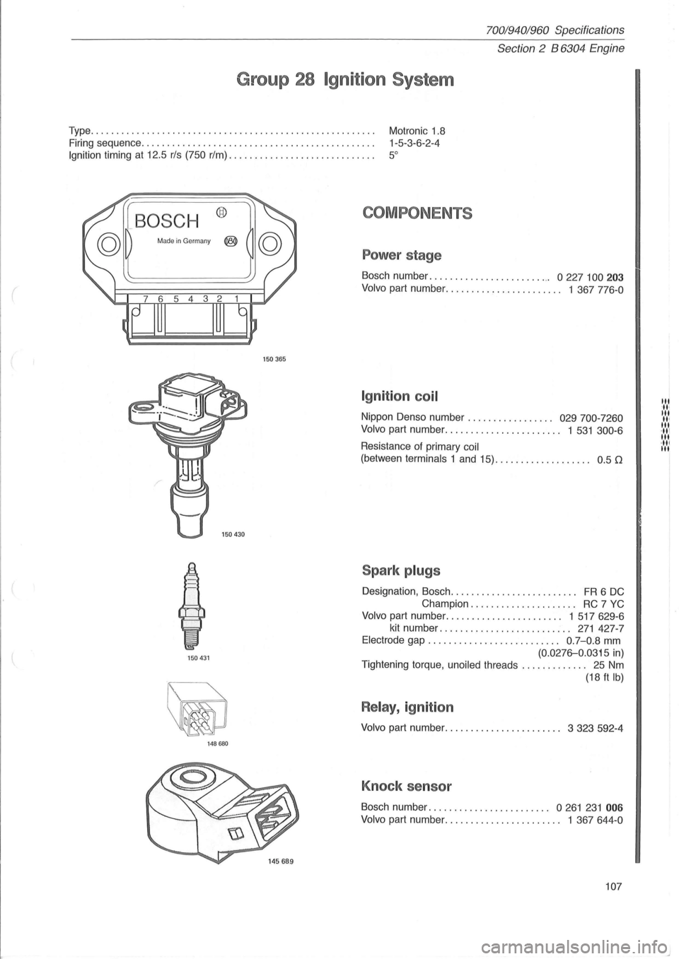
Power stage
Bosch number. . . . . . . . . . . . . . . . . . . . . . . .. 0 227 100 203
Volvo part number. . . . . . . . . . . . . . . . . . . . . .. 1 367 776-0
Ign ition coil
Nippon Denso number . . . . . . . . . . . . . . . .. 029 700-7260
Volvo
part number . . . . . . . . . . . . . . . . . . . . . .. 1 531 300-6
Resistance of primary coil
(between terminals 1 and 15). . . . . . . . . . . . . . . . . .. 0 .5 [2
Spark plugs
Designation, Bosch ......................... FR 6 DC
Champion. . . . . . . . . . . . . . . . . . .
.. RC 7 YC
Volvo part number. . . . . . . . . . . . . . . . . . . . . .. 1 517629-6
kit number .......................... 271 427-7
Electrode gap. . . . . . . . . . . . . . . . . . . . . . . . . . 0.7-0.8 mm
(0.0276-0.0315 in)
Tightening torque,
unoiled threads . . . . . . . . . . . . . 25 Nm
(18 ft Ib)
Relay, ignition
Volvo part number. . . . . . . . . . . . . . . . . . . . . .. 3 323 592-4
Knock senso r
Bosch number ........................ 0261 231 006
Volvo part number . . . . . . . . . . . . . . . . . . . . . .. 1 367644-0
107
III 'IIt III II' III 'III III ,III III
Page 110 of 168
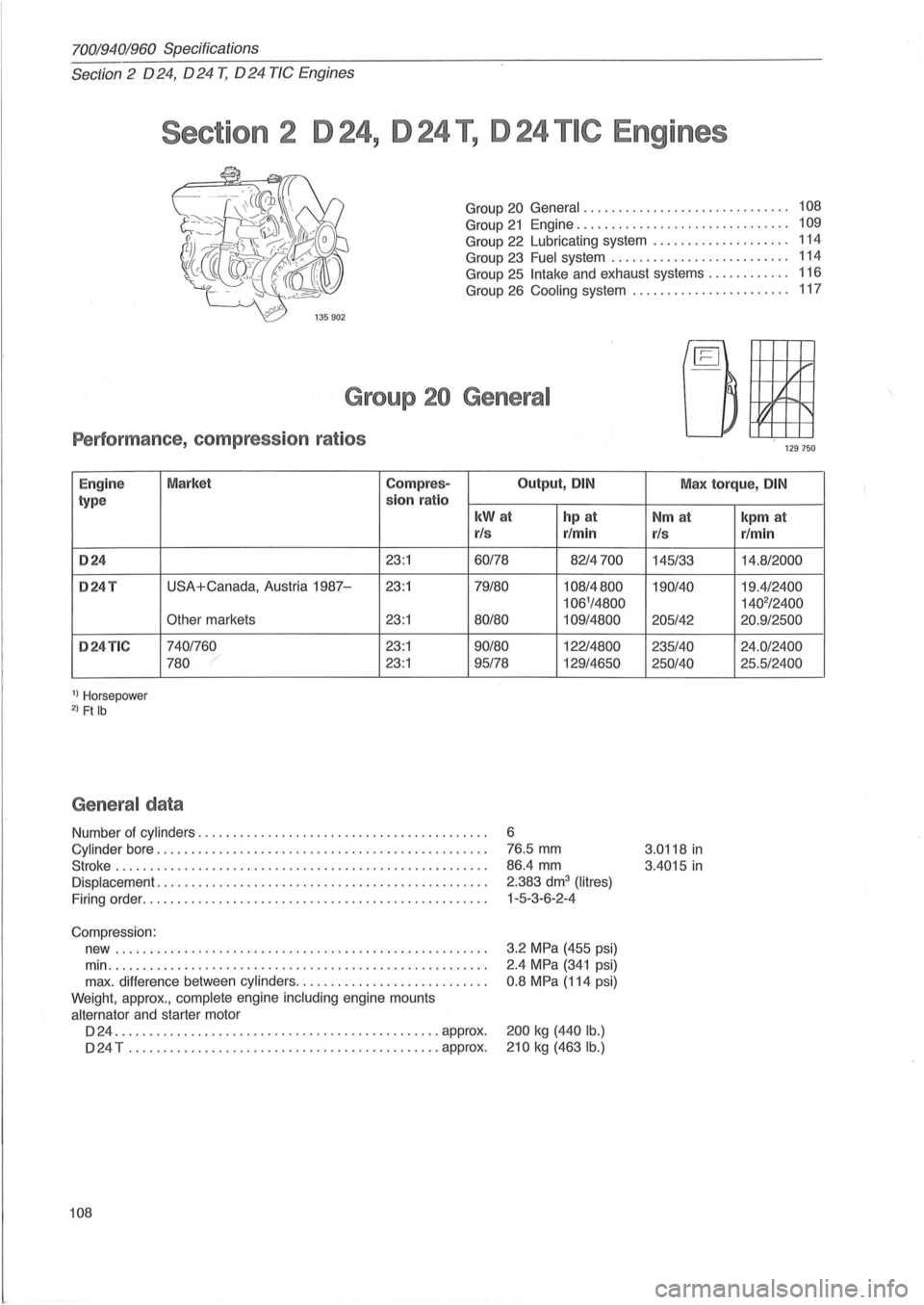
70019401960 Specifications
Section 2 024, 024 T, 024 TIC Engines
Section 2 D 24, D 24 T, D 24 TIC Engines
Group 20 General. . . . . . . . . . . . . . . . . . . . . . . . . . . . .. 108
Group 21 Engine..... ...................... .... 109
Group 22 Lubricating system . . . . . . . . . . . . . . . . . . . . 114
Group 23
Fuel system . . . . . . . . . . . . . . . . . . . . . . . . . . 114
Group 25
Intake and exhaust systems. . . . . . . . . . .. 116
Group 26
Cooling system .. . . . . . . . . . . . . . . . . . . . .. 117
Group 20 Genera l
Performance , co mpress io n r atios
Engine Market Compre
s-Output, DIN
type sion
ra tio
kWat hp at
r/s r/min
024 23:1 60/78 8214700
024T USA+Canada, Austria 1987-23:1 79/80 108/4800
106'/4800
Other
markets 23:1 80/80 109/4800
024TIC 740/760 23:1 90/80 12214800
780
23:1 95/78 129/4650
1) Horsepower 2) Ft Ib
Ge ne ra l da ta
Number of cylinders .. ............... ........................ .
Cylinder bore .................... ...................... ..... .
Stroke ..
............................ ............. ... ....... .
Displacement ........ ....................................... .
Firing order ..
............................................... .
Compression: new
..................................................... .
min
....................... ............................... .
max. difference between
cylinders ........................... .
Weight, approx.,
complete engine including engine mounts
alternator and starter motor
D 24 ....
.............. ... ............ ... ........... approx .
D 24 T
............................................. approx.
108
6
76.5 mm
86.4 mm
2.383 dm
3 (Iitres)
1-5-3-6-2 -4
3.2
MPa (455 psi)
2.4
MPa (341 psi)
0.8 MPa (114 psi)
200 kg (440 lb.)
210
kg (463 lb .)
,/1-'"
It
t1 '
'29750
Max torque, DIN
Nm at
r/s
145/33
190/40
205/42
235/40
250/40
3.0118
in
3.4015 in
kpm at
r/min
14.8/2000
19.4/2400
140
2/2400
20.9/2500
24 .0/2400
25 .5/2400
Page 115 of 168
(
70019401960 Specifications
Section
2 024, 024 T, 024 TIC Engines
Tig ht enin g to rqu es
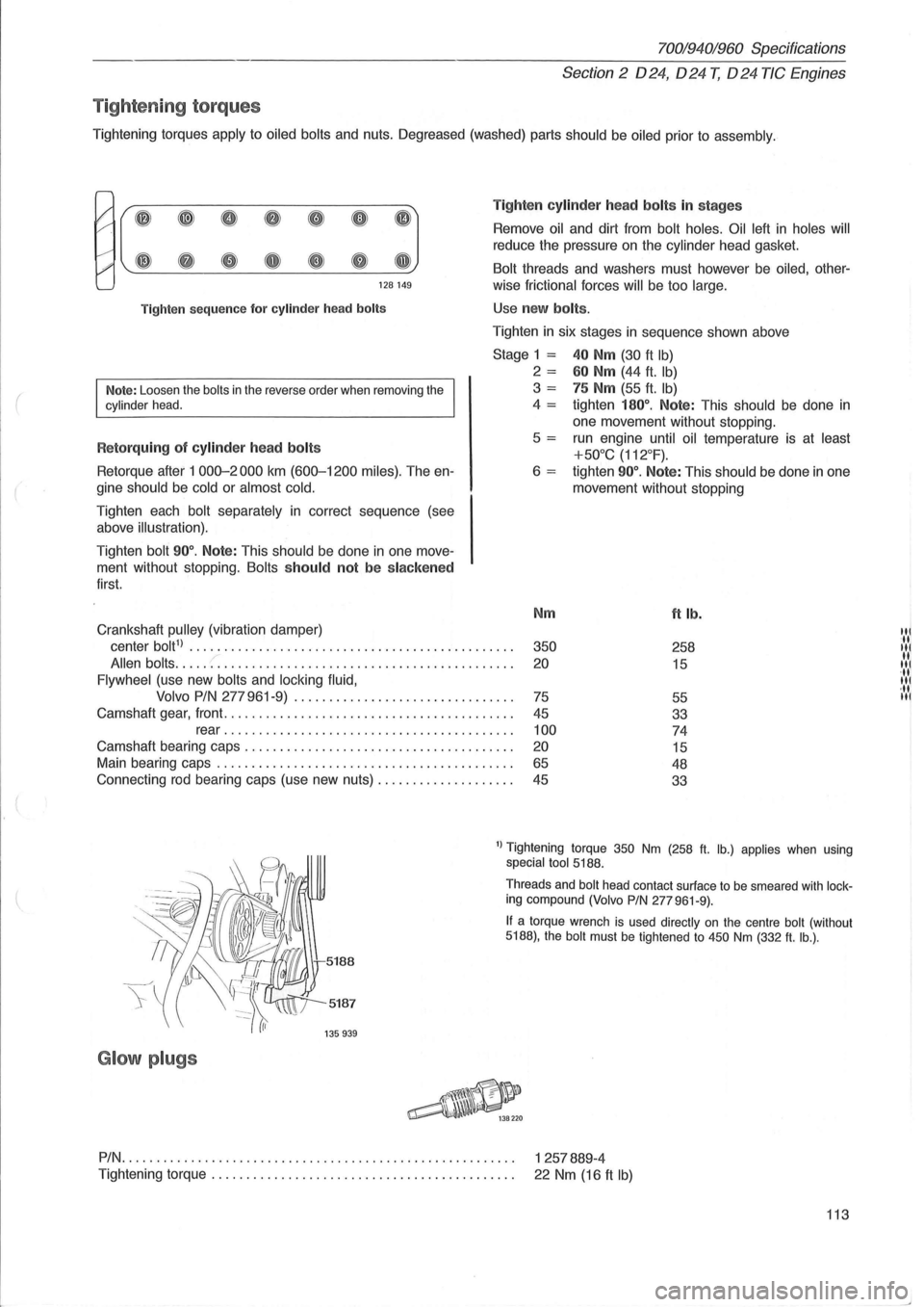
Tightening torques apply to oiled bolts and nuts. Oegreased (washed) parts should be oiled prior to assembly .
I' ~ ~ 0 8 CD 0 (IJ
#' ~ G e Q e Q GJ
128149
Tighten
sequence for cylinder head bolts
Note: Loosen the bolts in the reverse order when removing the cylinder head.
R etorquing of cylinder head bolts
Retorque after 1 000-2000 km (600-1200 miles). The en
gine
should be cold or almost cold.
Tighten each bolt separately in correct sequence (see
above
illustration).
Tighten bolt 90°. Note: This should be done in one move
ment without stopping.
Bolts should not be slacken ed
first.
Crankshaft
pulley (vibration damper) Ti
g
hten cylinde r h ea d bolts in stages
Remove oil and dirt from bolt holes. Oil left in holes will
reduce the pressure on the cylinder head gasket.
Bolt threads and washers must however be oiled, other-
wise
frictional forces will be too large.
Use new bolts .
Tighten in six stages in sequence shown above
Stage 1 = 40 Nm (30 ft Ib)
2 = 60 Nm (44 ft. Ib)
3 = 75 Nm (55 ft. Ib)
4 = tighten 180°. Note: This should be done in
one movement without stopping .
5
= run engine until oil temperature is at least
+50°C (112°F).
6 = tighten 90°. Note: This should be done in one
movement without stopping
Nm
ft lb.
center bolt1) ............................... ............... . 350 258
Allen bolts ..... :: ......................................... . 20 15
Flywheel (use new bolts and locking fluid,
Volvo PIN
277 961-9) ............................... .
75
55
Camshaft gear, front
......................................... .
45
33
rear
....................................... .. . 100 74
Camshaft bearing caps .................................... .. . 20 15
Main bearing caps .......................................... .
65 48
Connecting rod bearing caps (use new nuts)
................... .
45
33
1) Tightening torque 350 Nm (258 ft. lb.) applies when using special tool 5188.
5187
G lo w plugs
Threads and bolt head contact surface to be smeared with locking compound (Volvo PIN 277961-9).
If a torque wrench is used directly on the centre bolt (without 5188), the bolt must be tightened to 450 Nm (332 ft. lb.) .
PIN.
. . . . . . . . . . . . . . . . . . . . . . . . . . . . . . . . . . . . . . . . . . . . . . . . . . . . . . . . 1 257889-4
Tightening
torque. . . . . . . . . . . . . . . . . . . . . . . . . . . . . . . . . . . . . . . . . . . . 22 Nm (16 ft Ib)
113
'il IN 11 '11 11
·11 III
Page 117 of 168
(
l
70019401960 Specifications
Section
2 024, 024 T, 024 TIC Engines
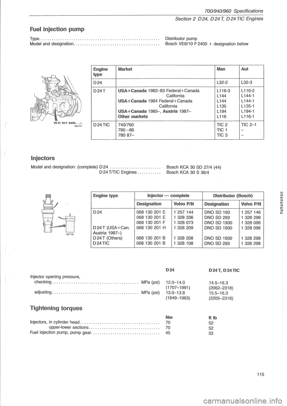
Fuel inject ion pump
Type ....................................................... . Distributor pump
Model and designation ....................................... .
Bosch VE6/10 F 2400 + designation below
VE 6/10 F 2400 ••. -. 136777
Injectors
I
Eng ine
type
024
o24T
o24TIC
Market
U
SA+Canada 1982-83 Federal+Canada
California
U
SA+Canada 1984 Federal+Canada
California
USA+Canada 1985-, Austria 1987-
Other markets
7401760
780 -86
78087-
Man
L32-2
L
116~3
L144
L144
L135
L194
L116
i 1'IC 2 : ' TIC 1
TIC 3
Model
and designation: (complete) 024 . . . . . . . . . . . . . . . . . . . . . . . . Bosch KCA 30 SO 27/4 (44)
024 TITIC Engines . . . . . . . . . . . Bosch KCA 30 S 36/4
Aut
L32-3
L 116-2
L 144 -1
L144-1
L
135-1
L194- 1
L116-1
TIC 2-1
-
-
Eng ine typ e Injector -.complete Distributor (Bosc h)
Designation
024 068130201 E
068130201 E
068130201 F
024 T (USA+Can . 068130201 H
136778 Austria 1987-)
024 T (Others) 068130201 B
o24TIC 068130201 B
Injector opening pressure,
checking. . . . . . . . . . . . . . . . . . . . . . . . . . . . . . . . . . . . . .
.. MPa (psi)
adjusting. . . . . . . . . . . . . . . . . . . . . . . . . . . . . . . . . . . . . . .. MPa (psi)
Tightening torques
Volvo PIN
1 257144
1 328336
1 328073
1 328209
1 328208
1 328 108
024
12.0-14.0
(1707-1991)
13.0-13.8
(1849-1963)
Nm
Injectors, in cylinder head. . . . . . . . . . . . . . . . . . . . . . . . . . . . . . . . . . . . . 70
upper-lower sections. . . . . . . . . . . . . . . . . . . . . . . . . . . . . . . . . 70
Fuel injection pump, pump gear. . . . . . . . . . . . . . . . . . . . . . . . . . . . . . . . 45
Designation
oNO SO 193
oNO SO 293
oNO SO 1930
oNO
SO 1930
oNO
SO 1930
oNO SO 293
024 T, 024 TIC
14.5-16 .3
(2062-2318)
15.5-16.3
(2205-2318)
ftlb
52
52
33
Volvo PIN
1 ,257146
1
328298
1 328096
1 328096
1 328298
1
328298
115
Page 118 of 168
70019401960 Specifications
Section
2 024, 024 T, 024 TIC Engines
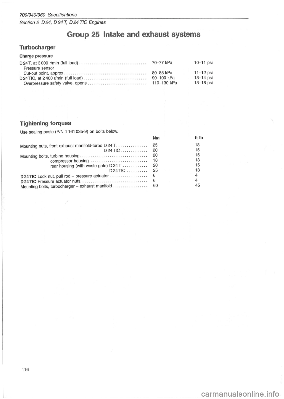
Group 25 Intake and exhaust systems
Turbocharger
Charge pressure
D 24 T, at 3000 rlmin (full load) ............................... .
Pressure sensor
Cut-out point, approx
.................................... .. .
D 24
TIC, at 2400 rlmin (full load) ............................. .
Overpressure safety valve, opens ........................... .
Tightening torques
Use sealing paste (PIN 1 161 035-9) on bolts below.
Mount ing nuts, front exhaust manifold-turbo D 24 T .............. . D24TIC ............ .
Mounting
bolts, turbine housing ............................... .
compressor housing
..................... ..... .
rear housing (with waste gate)
024 T ........... .
D24 TiC ......... .
024 TIC Lock nut, pull rod -pressure actuator ................. .
024 TIC Pressure actuator nuts ............................... .
Mounting
bolts, turbocharger -exhaust manifold ................ .
116
70-77 kPa
80-85 kPa
90-100
kPa
110-130 kPa
Nm
25
20
20
18
20
25
6
6
60
10-11 psi
11-12 psi
13-14 psi
13-18 psi
ftlb
18
15
15
13
15
18
4
4 45