1982 VOLVO 700 ground clearance
[x] Cancel search: ground clearancePage 19 of 168

(
70019401960 Specifications
Section
2 B 19, B 23 Engines
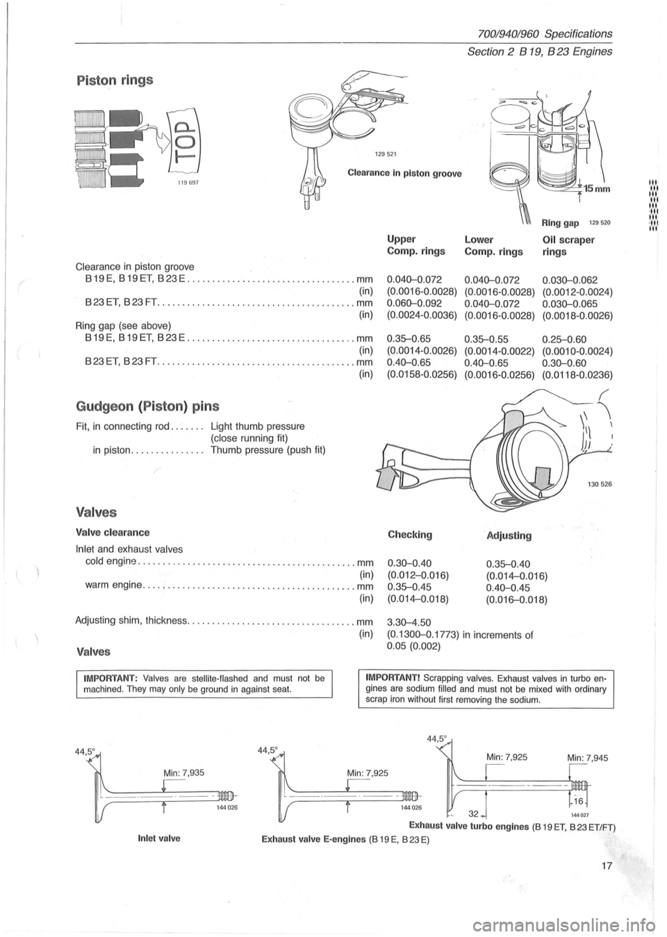
P iston rings
129521
Clearance In piston groove
Clearance in piston groove
819 E, 819 ET, 823 E .................................. mm
(in)
823ET, 823FT .............. .......................... mm
(in)
Ring gap (see above)
819E, 819ET, 823E .................................. mm
(in)
823ET, 823FT ................ .......... .............. mm
Gudgeon (Piston ) pins
Fit, in connecting rod. . . . . .. Light thumb pressure
(close running fit)
in piston. . . . . . . . . . . . . .. Thumb pressure (push fit)
Valves
Valve clearance
Inlet
and exhaust valves
(in)
cold engine ............................................ mm
(in) warm engine ........................................... mm
(in)
Adjusting shim, thickness .................................. mm
(in)
Valves
Upper
Camp.
rings
0.040-0 .072
(0. 0016-0.0028)
0.060-0 .092
(0.0024-0.0036)
0 .35-0.65
(0.0014 -0 .0026)
0.40-0 .
65
(0.0158-0.0256)
Checking
0.30-0.40
(0.012-0.Q16)
0.35-0.45
(0.014-0.018)
3 .
30-4.50
Ring gap 129 520
Lower Oil scraper
Camp.
rings rings
0.040-0.072 0.030-0.062
(0.0016 -0 .0028) (0.0012 -0.0024)
0.040-0.072 0.030-0.065
(0.0016-0.0028) (0.0018-0.0026)
0.35-0.55 0.25-0.60
(0.0014-0.0022) (0.0010-0.0024)
0.40-0.65 0.30-0.60
(0.0016-0.0256) (0.0118-0.0236)
'Adjusting
0.35-0.40
(0. 014-0 .016)
0.40-0.45
(0. 016-0.018)
(0.1300-0 .1773)
in increments of
0.05 (0.002)
IMPORTANT: Valves are stellite-flashed and must not be machined . They may only be ground in against seat. IMPORTANT! Scrapping valves. Exhaust valves in turbo engines are sodium filled and must not be mixed with ordinary
scrap iron without first removing the sodium.
Min: 7,935
Inlet valve
44,5°
44,5 °
Min: 7,945
144027
Exhaust valve turbo engines (8 19 ET, 823 ET/FT)
Exhaust valve E-engines (8 19 E, 823 E)
17
III' III III
III
III ,111 III ·111 III
Page 40 of 168

70019401960 Specifications
Section 2 B 200, B 230 Engines
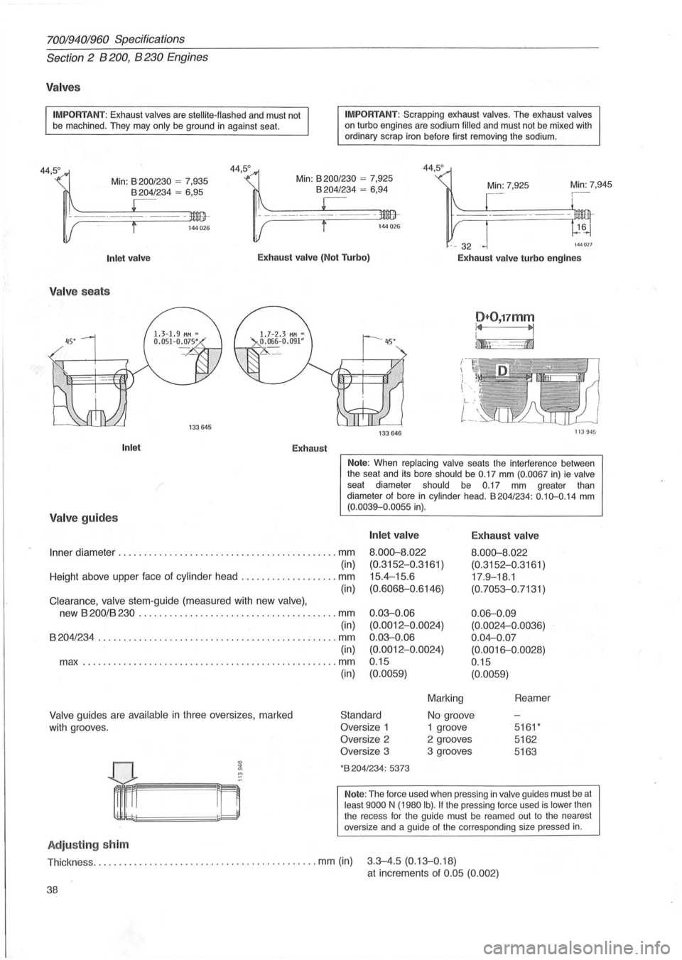
Valves
IMPORTANT: Exhaust valves are stellite-flashed and must not
be machined . They may only be ground in against seat.
Min:
8200/ 230 = 7,935 8204/234 = 6 ,95
IMPORTANT : Scrapping exhaust valves. The exhaust valves on turbo engines are sodium filled and must not be mixed with
ordinary scrap iron before first removing the sodium.
Min: 7,945
144 027
Inlet valve Exhaust valve (Not Turbo)
Exhaust valve turbo engines
Valv e sea ts
Inlet Exhaust
Valve guides
D+O,17mm
~F-~
133 646 113945
Note: When replacing valve seats the interference between
the seat and its bore should be 0.17 mm (0.0067 in) ie valve seat diameter should be 0.17 mm greater than
diameter of bore in cylinder head . 8204/234: 0.10-0.14 mm (0.0039-0 .0055 in).
Inner diameter ........................................... mm
Inlet valve
8.000-8.022
(0.3152-0.3161 )
15.4--15.6
(0.6068-0.6146)
E xhaust valve
8.000-8.022
(0.3152-0 .3161 )
17 .9-18.1
(0.7053-0. 7131 )
(in)
Height above upper face of cylinder head
................... mm
(in)
Clearance, valve stem-guide (measured with new valve),
new 8200/8230 ....................................... mm 0.03-0.06
(0.0012-0.0024)
0.03-0.06
(0.0012-0.0024)
0.15 0
.
06-0.09
(0.0024--0.0036)
0 .04--0 .07
(0.0016-0 .0028)
0.15
(in)
8204/234 ....... ........................................ mm
(in)
max
.............. .................................... mm
Valve guides are available in three oversizes , marked
with grooves.
Adju sting sh im
(in) (0.0059)
Standard
Oversize 1
Oversize 2
Oversize 3
*8204/234: 5373
(0.0059)
Marking
No groove
1 groove
2 grooves
3 grooves Reamer
5161 *
5162
5163
Note:
The force used when pressing in valve guides must be at least 9000 N (1980 Ib). If the pressing force used is lower then
the recess for the guide must be reamed out to the nearest
oversize and a guide
of the corresponding size pressed in.
Thickness ............................................ mm (in) 3.3-4.5 (0.13-0. 18)
at increments of 0.05 (0.002)
38
Page 74 of 168

70019401960 Specifications
Section
2 B 28 Engine
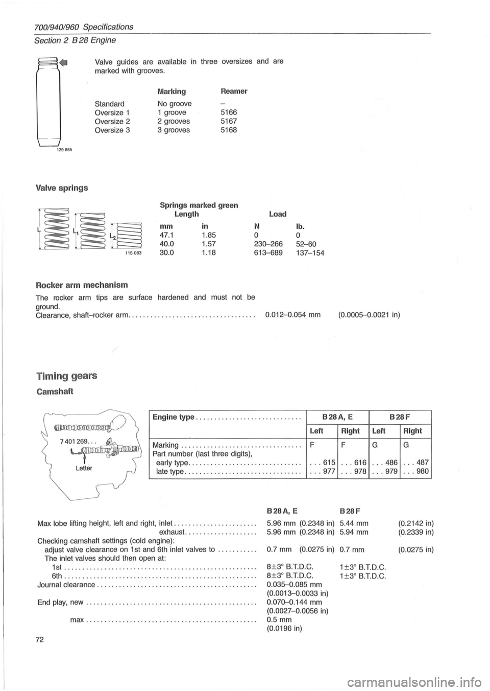
.. Valve guides are available in three oversizes and are
marked with grooves.
Standard
Oversize 1
Oversize 2
Oversize 3
129865
Valve springs
115083
Rocker arm mechanism
Marking Reamer
No groove
1 groove 5166
2 grooves 5167
3 grooves 5168
Springs marked green
Length
mm
in
47.1 1.85
40.0 1.57
30.0 1 .18
Load
N
o
230-266
613-689
The rocker arm tips are surface hardened and must not
be
ground.
lb.
o
52-60
137-154
Clearance. shaft-rocker arm. . . . . . . . . . . . . . . . . . . . . . . . . . . . . . . . . . . 0.012-0 .054 mm (0.0005-0.0021 in)
Timing gears
Camshaft
Engine type ............................. B28A, E B28F
Left
Right
Marking ................................. F
F
Part number
(last three digits).
early type ............................... .. .615 . . .616
late type ................................ . .. 977 .. .978
740~
Letter
B28A, E B28F
Max lobe lifting height. left and right. inlet ...................... .
exhaust. .
................ "
5.96 mm (0.2348 in) 5.44 mm
5.96 mm (0.2348 in) 5.94 mm
Checking camshaft settings (cold engine):
adjust
valve clearance on 1 st and 6th inlet valves to .......... . 0.7 mm (0.0275 in) 0.7 mm
The inlet valves should then open at:
Left
G
... 486
. . .979
1 st .................................................... . 8±3° B.T.D.C. 1 ±3° B.T.D.C.
6th .. ,
................................................. . 8±3° B.T.D.C. 1 ±3° B.T.D.C.
Journal clearance ........................................... . 0.035-0.085 mm
(0.0013-0.0033 in)
End play, new .............................................. . 0.070-0.144 mm
(0.0027-0.0056 in)
max .............................................. . 0.5 mm
(0.0196 in)
72
Right
G
... 487
... 980
(0.2142
in)
(0.2339 in)
(0. 0275 in)
Page 91 of 168

(
70019401960 Specifications
Section
2 B 280 Engine
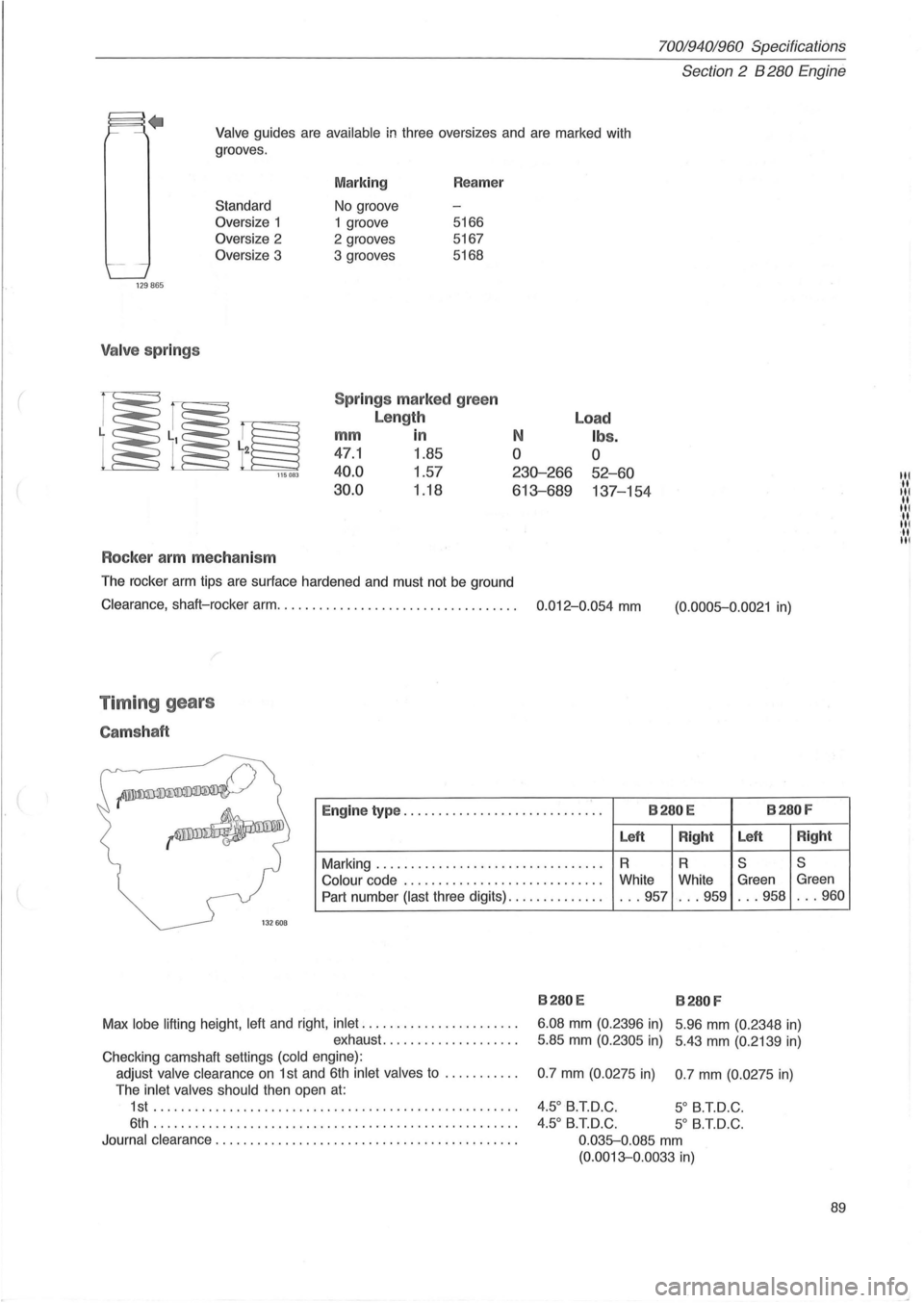
Valve guides are available in three oversizes and are marked with
grooves .
129865
Valve springs
Standard
Oversize 1
Oversize 2
Oversize 3
115083
Rocker arm mechanism
Marking
No groove
1 groove
2 grooves
3 grooves Reamer
5166
5167
5168
Spr ings marked green
Length
mm in
47.1 1.85
40.0 1.57
30.0 1.18
N
o
230-266
613-689
The rocker arm tips are surface hardened and must not be ground
Load
Ibs.
o
52-60
137-154
Clearance, shaft-rocker arm. . . . . . . . . . . . . . . . . . . . . . . . . . . . . . . . . . . 0.012-0.054 mm
Timing gears
Camshaft
(0.0005-0.0021 in)
~
--~
Engine type ............................. B280E B280F
Left
Right Left
Right
Marking
........................... ...... R R S S
Colour
code ...... ... .................... White
White Green Green
Part number (last three digits)
.............. ... 957 ... 959 . .. 958 . .. 960
1
32608
B280E B280 F
Max lobe lifting height . left and right. inlet
...................... .
exhaust
........... ' " ... .. . 6.08
mm (0.
2396 in) 5 .96 mm (0.2348 in)
5.85 mm (0.2305 in) 5.43 mm (0.2139 in)
Checking camshaft settings (cold engine) :
adjust valve clearance
on 1 st and 6th inlet valves to .......... .
The inlet valves should then open
at:
1st ...... .................... .......................... .
6th . ................................................... .
Journal clearance
............................... ............ . 0.7
mm (0.0275 in) 0.7 mm (0.
0275 in)
4.50 B.T.D.C. 5 0 B.T.D.C .
4.50 B.T.D.C. 5
0 B.T.D.C.
0 .035-0.085
mm
(0.0013-0.0033 in)
89
III .. III .. III ... III ·11 III